Page is loading ...

METRA. The World’s best kits.
™
metraonline.com
© COPYRIGHT 2004-2016 METRA ELECTRONICS CORPORATION
REV. 5/16/2016 INST99-7431
Installation instructions for part 99-7431
CAUTION!
All accessories, switches, climate controls panels, and
especially air bag indicator lights must be connected before cycling
the ignition. Also, do not remove the factory radio with the key in the
on position, or while the vehicle is running.
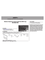
• DIN radio provision with pocket
• ISO DIN radio provision with pocket
• ISO DDIN radio provision
• A) ISO DDIN trim plate • B) ISO DDIN brackets • C) Radio housing • D) ISO DIN trim plate • E) Bracket set #1
• F) Bracket set #2 • G) Bracket set #3 • H) ISO DIN brackets • I) (4) #8 x 1/2 Phillips screws
KIT FEATURES
KIT COMPONENTS
WIRING & ANTENNA CONNECTIONS (sold separately)
Wiring Harness:
• Please visit metraonline.com for harness options
Antenna Adapter:
• Please visit metraonline.com for antenna options
Nissan Multi Kit 1993-2004
99-7431
A B
• Panel removal tool • Cutting tool
• Phillips screwdriver • Socket wrench
TOOLS REQUIRED
APPLICATIONS
See application list inside cover
C D E
F G
H
I

99-7431
2
Applications Table of Contents
INFINITI
I-30 1996-1999
QX4 1997-2000
MERCURY
Villager 1993-2002
NISSAN
200SX 1995-1998
240SX 1995-1998
Altima 1998-2001
Frontier 1998-2004
NISSAN (Cont’d)
Maxima 1995-1999
Maxima (without wrap
around radio) 2000-2003
Pathfinder 1996-2000
Pathfinder (without NAV)
2001-2002
Pathfinder SE 2003-2004
Quest 1993-2003
Sentra 1995-1999
Xterra 2000-2004
Dash Disassembly ...................... 3-13
Infiniti
- I-30 1996-1999 ............................ 3
- QX4 1997-2000 ............................ 3
Mercury
- Villager 1993-1995 ....................... 4
- Villager 1996-1998 ....................... 5
- Villager 1999-2002 ....................... 6
Nissan
- 200SX 1995-1998 ........................ 7
- 240SX 1995-1998 ........................ 8
- Altima 1998-2001 ......................... 9
- Frontier 1998-2001 ..................... 10
- Frontier 2002-2004 ..................... 11
- Maxima 1995-1999 ...................... 3
- Maxima (without wrap around
radio) 2000-2003 ....................... 12
- Pathfinder 1996-2000 ................... 3
Nissan (Cont’d)
- Pathfinder (without NAV)
2001-2002 ................................. 13
- Pathfinder SE 2003-2004 ............ 13
- Quest 1993-1995 .......................... 4
- Quest 1996-1998 .......................... 5
- Quest 1999-2003 .......................... 6
- Sentra 1995-1999 ........................ 7
- Xterra 2000-2001 ....................... 10
- Xterra 2002-2004 ....................... 11
Kit Preparation ................................14
Kit Assembly
- DIN radio provision with pocket ... 15
- ISO DIN radio provision with pocket .15
- ISO DDIN radio provision ............. 15
Final Assembly ...............................16

99-7431
Dash Disassembly
3
Infiniti I-30 1996-1999
Nissan Maxima 1995-1999
1. Unclip the gear shifter trim bezel.
2.
Remove (1) screw to the left of the ashtray,
then unclip and remove the ashtray assembly
.
3. Remove (2) screws exposed.
4. Unclip the clock/vent assembly and remove
(2) screws exposed.
5. Remove the climate/radio assembly.
6. Remove the screws securing the climate/
radio to the trim bezel.
7.
Remove (8) screws securing the radio or radio/
pocket to the assembly and then remove
.
8.
Using a hammer, flatten the protruding screw
holes on the factory mounting brackets
.
9. If installing a single DIN aftermarket
radio: Cut and remove all mounting tabs
on the radio housing EXCEPT tabs “A”.
(Figure B)
Note: The tabs can be indentified by the
stamped letter on each tab.
Continue to kit assembly
(Figure A)
(Figure A)
(Figure B)
Infinity QX4 1997-2000
Nissan Pathfinder 1996-2000
1. Remove (2) screws from the base of the radio
trim bezel. (Figure A)
2. Unclip the bottom edge of the radio trim bezel
and disconnect the hazard light, defroster, wiper
and cligarette lighter wiring and remove the radio
trim bezel. (Figure A)
3. Remove (4) screws securing the factory radio and
disconnect the wiring
.
4.
If installing a double DIN aftermarket radio
:
Remove the factory brackets from the radio. Retain
the brackets for use during kit assembly.
5.
If installing a single DIN aftermarket radio:
Cut
Bracket Set #2 along the scored lines removing
the SHADED portions of the brackets. (Figure B)
6.
If installing a single DIN aftermarket radio:
Cut
and remove all mounting tabs EXCEPT tabs
“A” and “C”. (The tabs can be identified by the
stamped letter by each tab). (Figure B)
If installing a single DIN aftermarket radio,
continue to Kit Preparation.
If installing a double DIN aftermarket radio,
continue to Kit Assembly.
"A"
"A"
"C"
"C"
Single DIN
Only
"A"
"A"
"A"
"A"
(Figure B)

99-7431
4
Dash Disassembly
Mercury Villager 1993-1995
Nissan Quest 1993-1995
1. Remove (1) screw above the climate controls
and then unclip the radio trim bezel and remove.
(Figure A)
2. Remove (4) Phillips screws securing the factory
radio housing and remove the housing and
disconnect the wiring.
3. Remove (8) Phillips screws securing the factory
radio to the factory radio housing and remove the
radio.
4. If installing a double DIN aftermarket radio:
Remove the factory brackets from the radio.
Retain the brackets for use during kit assembly.
5. If installing a single DIN aftermarket radio:
Cut and remove all mounting tabs on Bracket Set
#2 EXCEPT tabs “D”. (The tabs can be identified
by the stamped letter by each tab). (Figure B)
If installing a single DIN aftermarket radio,
continue to Kit Preparation.
If installing a double DIN aftermarket radio,
continue to Kit Assembly.
(Figure B)
(Figure A)
"D"
"D
"
"D"
"D"
Single DIN
Only

99-7431
5
Dash Disassembly
(Figure B)
(Figure A)
Mercury Villager 1996-1998
Nissan Quest 1996-1998
1. Remove (4) plastic screws from the base of the storage compartment,
then pop out the (4) anchor clips securing the screws and remove the
compartment. (Figure A)
2.
Remove (2) Phillips screws from the base of the radio trim bezel and
then remove (2) Phillips screws above the radio opening
.
3. Remove the ashtray and then pull up and out on the radio trim bezel
and remove the bezel.
4. Remove (4) Phillips screws securing the factory radio housing and
remove the housing and disconnect the wiring.
5. Remove (2) Phillips screws securing the factory radio to the housing
and remove the radio.
6. If installing a double DIN aftermarket radio: Remove the factory
brackets from the radio. Retain the brackets for use during kit
assembly.
7. If installing a single DIN aftermarket radio: Cut and remove
all
mounting tabs on Bracket Set #2 EXCEPT tabs “D”. (The tabs can be
identified by the stamped letter by each tab). (Figure B)
If installing a single DIN aftermarket radio, continue to Kit Preparation.
If installing a double DIN aftermarket radio, continue to Kit Assembly.
"D"
"D
"
"D"
"D"
Single DIN
Only

99-7431
Dash Disassembly
Mercury Villager 1999-2002
Nissan Quest 1999-2003
1. Open the ashtray/cupholder assembly, depress the retaining clips on each
side and remove the assembly. (Figure A)
2. Remove (2) Phillips screws from each side of the ashtray/cupholder
assembly.
3. Remove (4) plastic rivets from the lower pocket and slide the pocket back.
Note: It is NOT necessary to remove the pocket. Unclip the dash trim bezel
and remove.
4. Remove (4) Phillips screws securing the factory radio and disconnect the
wiring.
5. If installing a double DIN aftermarket radio: Remove the factory
brackets from the radio. Retain the brackets for use during kit assembly.
6. If installing a single DIN aftermarket radio: Cut Bracket Set #1 along
the scored lines removing the SHADED portions of the brackets. (Figure B)
7. If installing a single DIN aftermarket radio: Cut and remove all
mounting tabs EXCEPT tabs “A”. (The tabs can be identified by the
stamped letter by each tab). (Figure B)
If installing a single DIN aftermarket radio, continue to Kit Preparation.
If installing a double DIN aftermarket radio, continue to Kit Assembly.
(Figure B)
(Figure A)
"A"
Single DIN
Only
6

99-7431
Dash Disassembly
Nissan 200SX 1995-1998
Nissan Sentra 1995-1999
1. Unclip the dummy plate from the center of the
switch panel (above the radio opening),then unclip
the radio trim bezel and remove. (Figure A)
2. Remove (4) Phillips screws securing the factory
radio and disconnect the wiring.
3. Remove (2) Phillips screws securing the factory
cupholder and remove
4. If installing a double DIN aftermarket radio:
Remove the factory brackets from the radio. Retain
the brackets for use during kit assembly.
5. If installing a single DIN aftermarket radio:
Cut Bracket Set #3 along the scored lines removing
the SHADED portions of the brackets. (Figure B)
6. If installing a single DIN aftermarket radio:
Cut and remove all mounting tabs EXCEPT tabs “A”.
(The tabs can be identified by the stamped letter by
each tab). (Figure B)
If installing a single DIN aftermarket radio,
continue to Kit Preparation.
If installing a double DIN aftermarket radio,
continue to Kit Assembly.
(Figure B)
(Figure A)
"A"
"A
"
"A"
"A"
"A"
"A"
Single DIN
Only
7

99-7431
Dash Disassembly
Nissan 240SX 1995-1998
1. Unclip the gear shifter trim bezel.
2. Remove (1) screw to the left of the ashtray, then
unclip and remove the ashtray assembly.
3. Remove (2) screws exposed.
4. Unclip the clock/vent assembly and remove (2)
screws exposed.
5. Remove the climate/radio assembly.
6. Remove the screws securing the climate/radio
to the trim bezel.
7. Remove (8) screws securing the radio or radio/
pocket to the assembly and then remove.
8. Using a hammer, flatten the protruding screw
holes on the factory mounting brackets.
9. If installing a single DIN aftermarket radio:
Cut and remove all mounting tabs on the radio
housing EXCEPT tabs “B” and “C”. (Figure B)
Note: The tabs can be identified by the stamped
letter on each tab.
Continue to kit assembly
(Figure B)
(Figure A)
"B"
"B"
"C"
"C"
Single DIN
Only
8

99-7431
Dash Disassembly
Nissan Altima 1998-2001
1. Unclip the gear shifter trim bezel and remove (2)
Phillips screws exposed. (Figure A)
2. Remove (2) Phillips screws above the radio
opening and unclip the radio trim bezel. (Figure A)
3. Remove (4) Phillips screws from the factory radio
and disconnect the wiring.
4. If installing a double DIN aftermarket radio:
Remove the factory brackets from the radio.
Retain the brackets for use during kit assembly.
5. If installing a single DIN aftermarket radio: Cut
Bracket Set #3 along the scored lines removing
the SHADED portions of the brackets. (Figure B)
6. If installing a single DIN aftermarket radio: Cut
and remove all mounting tabs EXCEPT tabs “B”.
(The tabs can be identified by the stamped letter
by each tab). (Figure B)
If installing a single DIN aftermarket radio,
continue to Kit Preparation.
If installing a double DIN aftermarket radio,
continue to Kit Assembly.
(Figure B)
(Figure A)
"B
"
"B"
"B"
"B"
Single DIN
Only
9

99-7431
10
Dash Disassembly
Nissan Frontier 1998-2001
Nissan Xterra 2000-2001
1. Remove the ashtray and (2) Phillips screws
exposed in the ashtray cavity and then unclip
the radio trim bezel and remove. (Figure A)
2. Remove (4) Phillips screws securing the
factory radio and disconnect the wiring.
3. If installing a double DIN aftermarket
radio: Remove the factory brackets from the
radio. Retain the brackets for use during kit
assembly.
4.
If installing a single DIN aftermarket
radio: Cut
Bracket Set #2 along the scored
lines removing the SHADED portions of the
brackets. (Figure B)
5.
If installing a single DIN aftermarket radio:
Cut
and remove all mounting tabs EXCEPT
tabs “A” and “B”. (The tabs can be identified
by the stamped letter by each tab). (Figure B)
If installing a single DIN aftermarket radio,
continue to Kit Preparation.
If installing a double DIN aftermarket radio,
continue to Kit Assembly.
(Figure B)
(Figure A)
"A"
"A"
"B"
"B"
Single DIN
Only

99-7431
11
Dash Disassembly
Nissan Frontier 2002-2004
Nissan Xterra 2002-2004
1. Unclip the gear shifter trim bezel and remove.
2. Remove (2) Phillips screws exposed in the shifter cavity.
3. Remove (2) Phillips screws under the climate control cluster and then
unclip the radio trim bezel and remove. (Figure A)
4. Remove (4) Phillips screws securing the factory radio and disconnect the
wiring.
CAUTION: Do not cycle the key when removing a dash with passenger
airbag on/off switch).
5.
If installing a single DIN aftermarket radio: Cut
Bracket Set #2 along the
scored lines removing the SHADED portions of the brackets. (Figure B)
6.
If installing a single DIN aftermarket radio: Cut
Bracket Set #2 along the
scored lines removing the SHADED portions of the brackets. (Figure B)
7.
If installing a single DIN aftermarket radio: Cut
and remove all mounting
tabs EXCEPT tabs “A” and “B”. (The tabs can be identified by the stamped
letter by each tab). (Figure B)
If installing a single DIN aftermarket radio, continue to Kit Preparation.
If installing a double DIN aftermarket radio, continue to Kit Assembly.
(Figure B)
(Figure A)
"A"
"A"
"B"
"B"
Single DIN
Only

99-7431
12
Dash Disassembly
Nissan Maxima (without wrap around radio)
2000-2003
1. Unclip the vent/radio trim bezel assembly and
remove. (Figure A)
2. Remove the ashtray insert, and then (1) Phillips
screw exposed.
3. Unclip the ashtray/shifter trim bezel assembly
and then remove. (Figure A)
4. Remove (2) Phillips screws above the factory
radio, and (2) Phillips screws below the climate
control panel. (Figure A)
5. Remove the radio/climate-control-panel
assembly and disconnect the wiring.
6. If installing a double DIN aftermarket radio:
Remove the factory brackets from the radio.
Retain the brackets for use during kit assembly.
7. If installing a single DIN aftermarket radio:
Cut and remove all mounting tabs on the radio
housing. (Figure B)
Continue to kit assembly
(Figure B)
(Figure A)
Single DIN
Only

99-7431
13
Dash Disassembly
Nissan Pathfinder (without NAV) 2001-2002
Nissan Pathfinder SE 2003-2004
1. Using a panel removal tool, pry out on the
top of the vent assembly (w/ clock) and
remove. (Figure A)
2. Remove (2) Phillips screws from the top of
the radio trim bezel and remove. (Figure B)
3. Remove (4) Phillips screws securing the
factory radio and disconnect the wiring.
4. If installing a double DIN aftermarket
radio: Remove the factory brackets from
the radio. Retain the brackets for use
during kit assembly.
5. If installing a single DIN aftermarket
radio: Cut and remove all mounting tabs
from Bracket Set #1 EXCEPT tabs “B”.
(The tabs can be identified by the stamped
letter by each tab). (Figure C)
If installing a single DIN aftermarket radio,
continue to Kit Preparation.
If installing a double DIN aftermarket radio,
continue to Kit Assembly.
(Figure C)
"B
"
"B"
"B"
"B"
Single DIN
Only
(Figure A)
(Figure B)

99-7431
(Figure A) (Figure A)
Kit Preparation
Altima, Frontier, Pathfinder, Quest,
Villager, Xterra:
1. Cut and remove all the mounting
tabs from the radio housing.
2. Secure the appropriate bracket
to the radio housing using the (4)
Phillips
flat head screws provided.
(Figure A)
Continue to kit assembly
200SX, Sentra:
1. Cut and remove all the mounting
tabs from the radio housing.
2. Secure the right bracket to the
radio housing using the (2) Phillips
flat head screws provided. (Figure
A)
3. Secure the right bracket to the
factory cupholder using the (1)
factory screw and (1) locating pin.
(Figure A)
4. Secure the left bracket to the radio
housing using the (2) Phillips
flat
head screws provided. (Figure A)
5. Secure the left bracket to the
factory cupholder using the (1)
factory screw and (1) locating pin.
(Figure A)
Continue to kit assembly
14

99-7431
(Figure A) (Figure A)
PATENT
PENDING
PATENT
PENDIN
G
DIN radio provision with pocket
1. Remove the metal DIN sleeve
from the aftermarket radio.
2. Slide the sleeve into the radio
housing and secure by bending
the metal locking tabs down.
(Figure A)
3. Slide the radio back into the
sleeve until it clicks in. (Figure A)
Continue to final assembly
ISO DIN radio provision with pocket
1. Remove the metal DIN sleeve and
trim ring from the aftermarket radio
.
2.
Secure the ISO DIN brackets to the
radio using the screws supplied
with the radio
. (Figure A)
3. Slide the radio/bracket assembly
into the radio housing until the
side clips engage. (Figure A)
4. Attach the ISO DIN trim ring over
the radio. (Figure A)
Continue to final assembly
Kit Assembly
15
(Figure A)
(Figure B)
ISO DDIN radio provision
1. Slide the ISO DDIN brackets into
the ISO DDIN trim plate aligning
the holes in the trim plate to the
clips on the bracket. (Figure A)
2. Attach the factory mounting
brackets and the ISO DDIN trim
plate/bracket assembly to the radio
with the screws supplied with the
radio. (Figure B)
3.
Locate the factory wiring harness and
antenna connector in the dash, and
complete all necessary connections
to the radio. Metra recommends
using the proper mating adapter from
Metra and/or AXXESS. Test the radio
for proper operation.
4. Reassemble the dash in reverse
order of disassembly.

METRA. The World’s best kits.
™
metraonline.com
© COPYRIGHT 2004-2016 METRA ELECTRONICS CORPORATION
REV. 5/16/2016 INST99-7431
KNOWLEDGE IS POWER
Enhance your installation and fabrication skills by
enrolling in the most recognized and respected
mobile electronics school in our industry.
Log onto www.installerinstitute.com or call
800-354-6782 for more information and take steps
toward a better tomorrow.
Metra recommends MECP
certified technicians
Installation instructions for part 99-7431
IMPORTANT
If you are having difficulties with the
installation of this product, please call our
Tech Support line at 1-800-253-TECH.
Before doing so, look over the instructions a
second time, and make sure the installation
was performed exactly as the instructions
are stated. Please have the vehicle apart
and ready to perform troubleshooting steps
before calling.
1.
Locate the factory wiring
harness and antenna
connector in the dash and
complete all necessary
connections to the radio.
Metra recommends using
the proper mating adapter
from Metra and/or AXXESS.
Test the radio for proper
operation.
For the Nissan Maxima
1995-1999 /
Infiniti I-30 1996-1999:
1. Mount the completed
assembly to the factory
trim bezel and factory
bracket assembly using
the factory screws.
(Figure A)
2. Mount to the sub-dash
using the factory screws,
and then reassemble the
dash in reverse order of
disassembly.
For the Nissan Maxima
(without wrap around
radio) 2000-2003:
1. Mount the completed
assembly to the factory
bracket assembly using
the (4) Phillips flat-head
screws supplied.
2. Mount to the sub-dash
using the factory screws,
and then reassemble the
dash in reverse order of
disassembly.
For the Nissan 240SX 1995-1998
:
1. Mount the completed
assembly to the factory
trim bezel (via tabs “B”)
using the factory screws.
2.
Mount to the sub-dash (via
tabs “C”) using the factory
screws, and then reassemble
the dash in reverse order of
disassembly.
For all other applications:
1.
Reassemble the dash in
reverse order of disassembly.
Final Assembly
(Figure A)
/