Anritsu MS20xxC User manual
- Category
- Measuring, testing & control
- Type
- User manual
This manual is also suitable for

User Guide
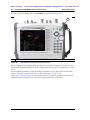
VNA Master™ Model MS20xxC
Vector Network Analyzer with
Spectrum Analyzer
MS2026C
VNA Frequency: 5 kHz to 6 GHz
MS2027C
VNA Frequency: 5 kHz to 15 GHz
MS2028C
VNA Frequency: 5 kHz to 20 GHz
MS2036C
VNA Frequency: 5 kHz to 6 GHz
SPA Frequency: 9 kHz to 9 GHz
MS2037C
VNA Frequency: 5 kHz to 15 GHz
SPA Frequency: 9 kHz to 15 GHz
MS2038C
VNA Frequency: 5 kHz to 20 GHz
SPA Frequency: 9 kHz to 20 GHz
Anritsu Company
490 Jarvis Drive
Morgan Hill, CA 95037-2809
USA
Part Number: 10580-00305
Revision: J
Published: October 2014
Copyright 2010, 2014 Anritsu Company
ООО "Техэнком" Контрольно-измерительные приборы и оборудование www.tehencom.com

ООО "Техэнком" Контрольно-измерительные приборы и оборудование www.tehencom.com

WARRANTY
The Anritsu products listed on the title page are warranted against defects in materials and
workmanship for three years from the date of shipment.
Anritsu’s obligation covers repairing or replacing products which prove to be defective during the
warranty period. Buyers shall prepay transportation charges for equipment returned to Anritsu for
warranty repairs. Obligation is limited to the original purchaser. Anritsu is not liable for consequential
damages. Accessories included with this product are not included in the standard warranty.
LIMITATION OF WARRANTY
The foregoing warranty does not apply to Anritsu connectors that have failed due to normal wear. Also,
the warranty does not apply to defects resulting from improper or inadequate maintenance,
unauthorized modification or misuse, or operation outside of the environmental specifications of the
product. No other warranty is expressed or implied, and the remedies provided herein are the Buyer’s
sole and exclusive remedies.
DISCLAIMER OF WARRANTY
DISCLAIMER OF WARRANTIES. TO THE MAXIMUM EXTENT PERMITTED BY APPLICABLE
LAW, ANRITSU COMPANY AND ITS SUPPLIERS DISCLAIM ALL WARRANTIES, EITHER
EXPRESSED OR IMPLIED, INCLUDING, BUT NOT LIMITED TO, IMPLIED WARRANTIES OF
MERCHANTABILITY AND FITNESS FOR A PARTICULAR PURPOSE, WITH REGARD TO THE
PRODUCT. THE USER ASSUMES THE ENTIRE RISK OF USING THE PRODUCT. ANY LIABILITY
OF PROVIDER OR MANUFACTURER WILL BE LIMITED EXCLUSIVELY TO PRODUCT
REPLACEMENT.
NO LIABILITY FOR CONSEQUENTIAL DAMAGES. TO THE MAXIMUM EXTENT PERMITTED BY
APPLICABLE LAW, IN NO EVENT SHALL ANRITSU COMPANY OR ITS SUPPLIERS BE LIABLE
FOR ANY SPECIAL, INCIDENTAL, INDIRECT, OR CONSEQUENTIAL DAMAGES WHATSOEVER
(INCLUDING, WITHOUT LIMITATION, DAMAGES FOR LOSS OF BUSINESS PROFITS,
BUSINESS INTERRUPTION, LOSS OF BUSINESS INFORMATION, OR ANY OTHER PECUNIARY
LOSS) ARISING OUT OF THE USE OF OR INABILITY TO USE THE PRODUCT, EVEN IF ANRITSU
COMPANY HAS BEEN ADVISED OF THE POSSIBILITY OF SUCH DAMAGES. BECAUSE SOME
STATES AND JURISDICTIONS DO NOT ALLOW THE EXCLUSION OR LIMITATION OF
LIABILITY FOR CONSEQUENTIAL OR INCIDENTAL DAMAGES, THE ABOVE LIMITATION MAY
NOT APPLY TO YOU.
TRADEMARK ACKNOWLEDGMENTS
VNA Master and easyMap Tools are trademarks of Anritsu Company.
Acrobat Reader is a registered trademark of Adobe Corporation.
NOTICE
Anritsu Company has prepared this manual for use by Anritsu Company personnel and customers as a
guide for the proper installation, operation and maintenance of Anritsu Company equipment and
computer programs. The drawings, specifications, and information contained herein are the property of
Anritsu Company, and any unauthorized use or disclosure of these drawings, specifications, and
information is prohibited; they shall not be reproduced, copied, or used in whole or in part as the basis
for manufacture or sale of the equipment or software programs without the prior written consent of
Anritsu Company.
UPDATES
Updates, if any, can be downloaded from the Anritsu Website at:
http://www.anritsu.com
For the latest service and sales contact information in your area, please visit:
http://www.anritsu.com/contact.asp
ООО "Техэнком" Контрольно-измерительные приборы и оборудование www.tehencom.com

ООО "Техэнком" Контрольно-измерительные приборы и оборудование www.tehencom.com

CE Conformity Marking
Anritsu affixes the CE Conformity marking onto its conforming products in accordance with
Council Directives of The Council Of The European Communities in order to indicate that
these products conform to the EMC and LVD directive of the European Union (EU).
C-tick Conformity Marking
Anritsu affixes the C-tick marking onto its conforming products in accordance with the
electromagnetic compliance regulations of Australia and New Zealand in order to indicate
that these products conform to the EMC regulations of Australia and New Zealand.
Notes On Export Management
This product and its manuals may require an Export License or approval by the government
of the product country of origin for re-export from your country.
Before you export this product or any of its manuals, please contact Anritsu Company to
confirm whether or not these items are export-controlled.
When disposing of export-controlled items, the products and manuals need to be broken or
shredded to such a degree that they cannot be unlawfully used for military purposes.
Mercury Notification
This product uses an LCD backlight lamp that contains mercury. Disposal may be regulated
due to environmental considerations. Please contact your local authorities for disposal or
recycling information.
ООО "Техэнком" Контрольно-измерительные приборы и оборудование www.tehencom.com

ООО "Техэнком" Контрольно-измерительные приборы и оборудование www.tehencom.com

MS20xxC UG PN: 10580-00305 Rev. J Safety-1
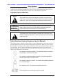
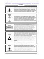
Safety Symbols
To prevent the risk of personal injury or loss related to equipment malfunction, Anritsu
Company uses the following symbols to indicate safety-related information. For your own
safety, please read the information carefully before operating the equipment.
Symbols Used in Manuals
Safety Symbols Used on Equipment and in Manuals
The following safety symbols are used inside or on the equipment near operation locations to
provide information about safety items and operation precautions. Ensure that you clearly
understand the meanings of the symbols and take the necessary precautions before operating
the equipment. Some or all of the following five symbols may or may not be used on all
Anritsu equipment. In addition, there may be other labels attached to products that are not
shown in the diagrams in this manual.
Danger
This indicates a risk from a very dangerous condition or procedure that
could result in serious injury or death and possible loss related to equipment
malfunction. Follow all precautions and procedures to minimize this risk.
Warning
This indicates a risk from a hazardous condition or procedure that could
result in light-to-severe injury or loss related to equipment malfunction.
Follow all precautions and procedures to minimize this risk.
Caution
This indicates a risk from a hazardous procedure that could result in loss
related to equipment malfunction. Follow all precautions and procedures to
minimize this risk.
This indicates a prohibited operation. The prohibited operation is indicated
symbolically in or near the barred circle.
This indicates a compulsory safety precaution. The required operation is
indicated symbolically in or near the circle.
This indicates a warning or caution. The contents are indicated symbolically
in or near the triangle.
This indicates a note. The contents are described in the box.
These indicate that the marked part should be recycled.
ООО "Техэнком" Контрольно-измерительные приборы и оборудование www.tehencom.com

Safety-2 PN: 10580-00305 Rev. J MS20xxC UG
For Safety
Warning
Always refer to the operation manual when working near locations at
which the alert mark, shown on the left, is attached. If the operation,
etc., is performed without heeding the advice in the operation
manual, there is a risk of personal injury. In addition, the equipment
performance may be reduced. Moreover, this alert mark is sometimes
used with other marks and descriptions indicating other dangers.
Warning
When supplying power to this equipment, connect the accessory
3-pin power cord to a 3-pin grounded power outlet. If a grounded
3-pin outlet is not available, use a conversion adapter and ground the
green wire, or connect the frame ground on the rear panel of the
equipment to ground. If power is supplied without grounding the
equipment, there is a risk of receiving a severe or fatal electric shock.
Warning
This equipment can not be repaired by the operator. Do not attempt to
remove the equipment covers or to disassemble internal
components. Only qualified service technicians with a knowledge of
electrical fire and shock hazards should service this equipment.
There are high-voltage parts in this equipment presenting a risk of
severe injury or fatal electric shock to untrained personnel. In
addition, there is a risk of damage to precision components.
Caution
Electrostatic Discharge (ESD) can damage the highly sensitive
circuits in the instrument. ESD is most likely to occur as test devices
are being connected to, or disconnected from, the instrument’s front
and rear panel ports and connectors. You can protect the instrument
and test devices by wearing a static-discharge wristband.
Alternatively, you can ground yourself to discharge any static charge
by touching the outer chassis of the grounded instrument before
touching the instrument’s front and rear panel ports and connectors.
Avoid touching the test port center conductors unless you are
properly grounded and have eliminated the possibility of static
discharge.
Repair of damage that is found to be caused by electrostatic
discharge is not covered under warranty.
Warning
This product is supplied with a rechargeable battery that could
potentially leak hazardous compounds into the environment. These
hazardous compounds present a risk of injury or loss due to
exposure. Anritsu Company recommends removing the battery for
long-term storage of the instrument and storing the battery in a
leak-proof plastic container. Follow the environmental storage
requirements specified in the product technical data sheet.
ООО "Техэнком" Контрольно-измерительные приборы и оборудование www.tehencom.com

MS20xxC UG PN: 10580-00305 Rev. J Contents-1
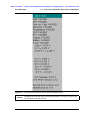
Table of Contents
Chapter 1—General Information
1-1 Introduction . . . . . . . . . . . . . . . . . . . . . . . . . . . . . . . . . . . . . . . . . . . . . . . . . 1-1
1-2 Contacting Anritsu . . . . . . . . . . . . . . . . . . . . . . . . . . . . . . . . . . . . . . . . 1-1
1-3 Anritsu Service Centers . . . . . . . . . . . . . . . . . . . . . . . . . . . . . . . . . . . . . 1-2
1-4 Additional Documents. . . . . . . . . . . . . . . . . . . . . . . . . . . . . . . . . . . . . . . . . 1-2
1-5 VNA Master Specifications . . . . . . . . . . . . . . . . . . . . . . . . . . . . . . . . . . . . 1-2
1-6 Identifying the Connections . . . . . . . . . . . . . . . . . . . . . . . . . . . . . . . . . . . . 1-3
1-7 Description . . . . . . . . . . . . . . . . . . . . . . . . . . . . . . . . . . . . . . . . . . . . . . . . . 1-4
1-8 Soft Carrying Case and Tilt Bail . . . . . . . . . . . . . . . . . . . . . . . . . . . . . . . . . 1-5
VNA Master Soft Carrying Case . . . . . . . . . . . . . . . . . . . . . . . . . . . . . . 1-5
VNA Master Tilt Bail Stand . . . . . . . . . . . . . . . . . . . . . . . . . . . . . . . . . . 1-7
1-9 Preventive Maintenance . . . . . . . . . . . . . . . . . . . . . . . . . . . . . . . . . . . . . 1-8
1-10 Calibration Requirements – Vector Network Analyzer . . . . . . . . . . . . . . 1-8
1-11 Annual Verification . . . . . . . . . . . . . . . . . . . . . . . . . . . . . . . . . . . . . . . . . . 1-8
1-12 Battery Replacement . . . . . . . . . . . . . . . . . . . . . . . . . . . . . . . . . . . . . . . . 1-9
1-13 ESD Cautions . . . . . . . . . . . . . . . . . . . . . . . . . . . . . . . . . . . . . . . . . . . 1-10
Chapter 2—Quick Start Guide
2-1 Introduction . . . . . . . . . . . . . . . . . . . . . . . . . . . . . . . . . . . . . . . . . . . . . . . . . 2-1
2-2 Turning the VNA Master On for the First Time . . . . . . . . . . . . . . . . . . . . . . 2-1
2-3 Front Panel Overview . . . . . . . . . . . . . . . . . . . . . . . . . . . . . . . . . . . . . . . . . 2-3
Front Panel Overview Image . . . . . . . . . . . . . . . . . . . . . . . . . . . . . . . . 2-4
Battery Charge LED (Green) . . . . . . . . . . . . . . . . . . . . . . . . . . . . . . . . . 2-5
Power LED (Green) . . . . . . . . . . . . . . . . . . . . . . . . . . . . . . . . . . . . . . . . 2-5
Fan Inlet and Exhaust Ports . . . . . . . . . . . . . . . . . . . . . . . . . . . . . . . . . 2-5
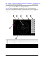
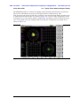
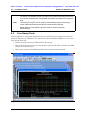
2-4 Typical Vector Network Analyzer Display . . . . . . . . . . . . . . . . . . . . . . . . 2-6
Instrument Settings Summary . . . . . . . . . . . . . . . . . . . . . . . . . . . . . . . 2-9
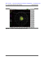
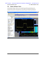
2-5 Typical Spectrum Analyzer Display . . . . . . . . . . . . . . . . . . . . . . . . . . . . 2-11
ООО "Техэнком" Контрольно-измерительные приборы и оборудование www.tehencom.com

Contents-2 PN: 10580-00305 Rev. J MS20xxC UG
Table of Contents (continued)
2-6 Front Panel Keys . . . . . . . . . . . . . . . . . . . . . . . . . . . . . . . . . . . . . . . . . . 2-12
Esc Key . . . . . . . . . . . . . . . . . . . . . . . . . . . . . . . . . . . . . . . . . . . . . . . . 2-12
Enter Key . . . . . . . . . . . . . . . . . . . . . . . . . . . . . . . . . . . . . . . . . . . . . . . 2-12
Arrow Keys . . . . . . . . . . . . . . . . . . . . . . . . . . . . . . . . . . . . . . . . . . . . . 2-12
Shift Key . . . . . . . . . . . . . . . . . . . . . . . . . . . . . . . . . . . . . . . . . . . . . . 2-12
Back Key . . . . . . . . . . . . . . . . . . . . . . . . . . . . . . . . . . . . . . . . . . . . . . . 2-12
Plus/Minus (+/–) Key . . . . . . . . . . . . . . . . . . . . . . . . . . . . . . . . . . . . . . 2-12
Number Keypad. . . . . . . . . . . . . . . . . . . . . . . . . . . . . . . . . . . . . . . . . . 2-13
Rotary Knob. . . . . . . . . . . . . . . . . . . . . . . . . . . . . . . . . . . . . . . . . . . . . 2-13
Function Hard Keys . . . . . . . . . . . . . . . . . . . . . . . . . . . . . . . . . . . . . . 2-13
Soft Keys . . . . . . . . . . . . . . . . . . . . . . . . . . . . . . . . . . . . . . . . . . . . . . 2-13
2-7 Soft Key Types . . . . . . . . . . . . . . . . . . . . . . . . . . . . . . . . . . . . . . . . . . . . 2-13
Select. . . . . . . . . . . . . . . . . . . . . . . . . . . . . . . . . . . . . . . . . . . . . . . . . . 2-13
Input. . . . . . . . . . . . . . . . . . . . . . . . . . . . . . . . . . . . . . . . . . . . . . . . . . . 2-14
Toggle . . . . . . . . . . . . . . . . . . . . . . . . . . . . . . . . . . . . . . . . . . . . . . . . . 2-14
Switching . . . . . . . . . . . . . . . . . . . . . . . . . . . . . . . . . . . . . . . . . . . . . . . 2-14
2-8 Parameter Setting. . . . . . . . . . . . . . . . . . . . . . . . . . . . . . . . . . . . . . . . . . . 2-15
2-9 Text Entry . . . . . . . . . . . . . . . . . . . . . . . . . . . . . . . . . . . . . . . . . . . . . . . . . 2-15
2-10 Mode Selector . . . . . . . . . . . . . . . . . . . . . . . . . . . . . . . . . . . . . . . . . . . . 2-19
2-11 Test Panel Connectors . . . . . . . . . . . . . . . . . . . . . . . . . . . . . . . . . . . . . . . 2-20
MS202xC Test Panel Connectors . . . . . . . . . . . . . . . . . . . . . . . . . . 2-20
MS203xC Test Panel Connectors . . . . . . . . . . . . . . . . . . . . . . . . . . . 2-21
LAN Connection . . . . . . . . . . . . . . . . . . . . . . . . . . . . . . . . . . . . . . . . 2-22
USB Interface - USB Type Mini-B . . . . . . . . . . . . . . . . . . . . . . . . . . . 2-24
USB Interface - USB Type A . . . . . . . . . . . . . . . . . . . . . . . . . . . . . . 2-24
2-12 VNA Master Connectors . . . . . . . . . . . . . . . . . . . . . . . . . . . . . . . . . . . . . . 2-25
External Power . . . . . . . . . . . . . . . . . . . . . . . . . . . . . . . . . . . . . . . . 2-25
Ext Trigger (50 ohm) . . . . . . . . . . . . . . . . . . . . . . . . . . . . . . . . . . . . . 2-25
Ext Freq Ref (50 ohm) . . . . . . . . . . . . . . . . . . . . . . . . . . . . . . . . . . . . 2-25
RF Detector (DIN) . . . . . . . . . . . . . . . . . . . . . . . . . . . . . . . . . . . . . . . 2-25
Port 1 (50 ohm) . . . . . . . . . . . . . . . . . . . . . . . . . . . . . . . . . . . . . . . . 2-26
Port 2 (50 ohm) . . . . . . . . . . . . . . . . . . . . . . . . . . . . . . . . . . . . . . . . . 2-26
Bias Input Port 1 . . . . . . . . . . . . . . . . . . . . . . . . . . . . . . . . . . . . . . . . 2-26
Bias Input Port 2 . . . . . . . . . . . . . . . . . . . . . . . . . . . . . . . . . . . . . . . . . 2-26
Bias Status LED . . . . . . . . . . . . . . . . . . . . . . . . . . . . . . . . . . . . . . . . . 2-26
Headset Jack . . . . . . . . . . . . . . . . . . . . . . . . . . . . . . . . . . . . . . . . . . . 2-27
ООО "Техэнком" Контрольно-измерительные приборы и оборудование www.tehencom.com

MS20xxC UG PN: 10580-00305 Rev. J Contents-3
Table of Contents (continued)
2-13 Connector Care . . . . . . . . . . . . . . . . . . . . . . . . . . . . . . . . . . . . . . . . . . . . 2-28
Connecting Procedure (for Type-N and Type-K) . . . . . . . . . . . . . . 2-28
Disconnecting Procedure . . . . . . . . . . . . . . . . . . . . . . . . . . . . . . . . . 2-28
GPS Antenna Connector . . . . . . . . . . . . . . . . . . . . . . . . . . . . . . . . . 2-29
Reference Output, 10 MHz (50 ohm) . . . . . . . . . . . . . . . . . . . . . . . . . 2-29
Spectrum Analyzer RF In (50 ohm) . . . . . . . . . . . . . . . . . . . . . . . . . . 2-29
2-14 Symbols and Indicators . . . . . . . . . . . . . . . . . . . . . . . . . . . . . . . . . . . . . . 2-30
Battery Symbol . . . . . . . . . . . . . . . . . . . . . . . . . . . . . . . . . . . . . . . . . 2-30
Hold . . . . . . . . . . . . . . . . . . . . . . . . . . . . . . . . . . . . . . . . . . . . . . . . . . 2-31
Single Sweep . . . . . . . . . . . . . . . . . . . . . . . . . . . . . . . . . . . . . . . . . . . 2-31
2-15 Memory Profile and Security Issues . . . . . . . . . . . . . . . . . . . . . . . . . . . 2-32
2-16 System Settings . . . . . . . . . . . . . . . . . . . . . . . . . . . . . . . . . . . . . . . . . . . 2-33
Power On Self Test . . . . . . . . . . . . . . . . . . . . . . . . . . . . . . . . . . . . . . . 2-33
Vector Network Analyzer Mode . . . . . . . . . . . . . . . . . . . . . . . . . . . . . 2-33
Spectrum Analyzer Mode . . . . . . . . . . . . . . . . . . . . . . . . . . . . . . . . . . 2-33
Frequency Blanking . . . . . . . . . . . . . . . . . . . . . . . . . . . . . . . . . . . . . . 2-33
2-17 File Types . . . . . . . . . . . . . . . . . . . . . . . . . . . . . . . . . . . . . . . . . . . . . . . . 2-34
File Management . . . . . . . . . . . . . . . . . . . . . . . . . . . . . . . . . . . . . . 2-34
Chapter 3—Power Monitor, Option 5
3-1 Introduction . . . . . . . . . . . . . . . . . . . . . . . . . . . . . . . . . . . . . . . . . . . . . . . 3-1
3-2 Using the Power Monitor . . . . . . . . . . . . . . . . . . . . . . . . . . . . . . . . . . . . . . 3-1
Zeroing the Power Monitor . . . . . . . . . . . . . . . . . . . . . . . . . . . . . . . . . 3-1
Measuring High Input Power Levels . . . . . . . . . . . . . . . . . . . . . . . . . . 3-1
Displaying Power in dBm or in Watts . . . . . . . . . . . . . . . . . . . . . . . . . . 3-2
Setting Relative Power . . . . . . . . . . . . . . . . . . . . . . . . . . . . . . . . . . . . 3-2
3-3 Power Monitor Display . . . . . . . . . . . . . . . . . . . . . . . . . . . . . . . . . . . . . . . 3-3
3-4 Power Monitor Menu . . . . . . . . . . . . . . . . . . . . . . . . . . . . . . . . . . . . . . . . . 3-3
Chapter 4—Secure Data Option 7
4-1 Introduction . . . . . . . . . . . . . . . . . . . . . . . . . . . . . . . . . . . . . . . . . . . . . . . . 4-1
4-2 Procedure . . . . . . . . . . . . . . . . . . . . . . . . . . . . . . . . . . . . . . . . . . . . . . . . . . 4-1
4-3 Calibration Setup . . . . . . . . . . . . . . . . . . . . . . . . . . . . . . . . . . . . . . . . . . 4-2
4-4 Memory Profile and Security Issues . . . . . . . . . . . . . . . . . . . . . . . . . . . . 4-3
4-5 Frequency Blanking . . . . . . . . . . . . . . . . . . . . . . . . . . . . . . . . . . . . . . . . . . 4-5
Chapter 5—File Management
5-1 Introduction . . . . . . . . . . . . . . . . . . . . . . . . . . . . . . . . . . . . . . . . . . . . . . . . . 5-1
5-2 File Types . . . . . . . . . . . . . . . . . . . . . . . . . . . . . . . . . . . . . . . . . . . . . . . . . 5-1
ООО "Техэнком" Контрольно-измерительные приборы и оборудование www.tehencom.com

Contents-4 PN: 10580-00305 Rev. J MS20xxC UG
Table of Contents (continued)
5-3 Managing Files . . . . . . . . . . . . . . . . . . . . . . . . . . . . . . . . . . . . . . . . . . . . . . 5-2
Save Files . . . . . . . . . . . . . . . . . . . . . . . . . . . . . . . . . . . . . . . . . . . . . . . 5-2
Save Dialog Box . . . . . . . . . . . . . . . . . . . . . . . . . . . . . . . . . . . . . . . . . . 5-3
Recall Files . . . . . . . . . . . . . . . . . . . . . . . . . . . . . . . . . . . . . . . . . . . . . . 5-4
Recall Dialog Box . . . . . . . . . . . . . . . . . . . . . . . . . . . . . . . . . . . . . . . . . 5-4
Copy Files . . . . . . . . . . . . . . . . . . . . . . . . . . . . . . . . . . . . . . . . . . . . . . . 5-5
Delete Files . . . . . . . . . . . . . . . . . . . . . . . . . . . . . . . . . . . . . . . . . . . . . . 5-6
Delete Dialog Box . . . . . . . . . . . . . . . . . . . . . . . . . . . . . . . . . . . . . . . . . 5-6
5-4 File Menu Overview . . . . . . . . . . . . . . . . . . . . . . . . . . . . . . . . . . . . . . . . . 5-7
5-5 File Menu . . . . . . . . . . . . . . . . . . . . . . . . . . . . . . . . . . . . . . . . . . . . . . . . . 5-8
Save Menu . . . . . . . . . . . . . . . . . . . . . . . . . . . . . . . . . . . . . . . . . . . . . . 5-9
Save Location Menu . . . . . . . . . . . . . . . . . . . . . . . . . . . . . . . . . . . . . 5-10
File Type Menu . . . . . . . . . . . . . . . . . . . . . . . . . . . . . . . . . . . . . . . . . 5-11
Save On ... Menu . . . . . . . . . . . . . . . . . . . . . . . . . . . . . . . . . . . . . . . . 5-12
Recall Menu . . . . . . . . . . . . . . . . . . . . . . . . . . . . . . . . . . . . . . . . . . . . 5-13
Copy Menu . . . . . . . . . . . . . . . . . . . . . . . . . . . . . . . . . . . . . . . . . . . . 5-14
Delete Menu . . . . . . . . . . . . . . . . . . . . . . . . . . . . . . . . . . . . . . . . . . . 5-15
Chapter 6—System Operations
6-1 Introduction . . . . . . . . . . . . . . . . . . . . . . . . . . . . . . . . . . . . . . . . . . . . . . . . . 6-1
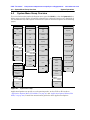
6-2 System Menu Group Overview . . . . . . . . . . . . . . . . . . . . . . . . . . . . . . . . . 6-2
6-3 Additional Menu Group . . . . . . . . . . . . . . . . . . . . . . . . . . . . . . . . . . . . . . . 6-3
6-4 System Menu . . . . . . . . . . . . . . . . . . . . . . . . . . . . . . . . . . . . . . . . . . . . . . 6-4
System Options Menu . . . . . . . . . . . . . . . . . . . . . . . . . . . . . . . . . . . . . 6-5
System Options 2/2 Menu . . . . . . . . . . . . . . . . . . . . . . . . . . . . . . . . . 6-6
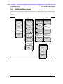
6-5 Application Options Menu (VNA Mode) . . . . . . . . . . . . . . . . . . . . . . . . . . 6-7
6-6 Time Domain Options Menu (VNA Mode) . . . . . . . . . . . . . . . . . . . . . . . . 6-8
6-7 Application Options Menu (SPA Mode) . . . . . . . . . . . . . . . . . . . . . . . . . . 6-9
6-8 Meas Gain Range Menu (VNA Mode) . . . . . . . . . . . . . . . . . . . . . . . . . . . 6-9
6-9 Display Settings Menu . . . . . . . . . . . . . . . . . . . . . . . . . . . . . . . . . . . . . 6-10
6-10 Reset Menu . . . . . . . . . . . . . . . . . . . . . . . . . . . . . . . . . . . . . . . . . . . . . . . 6-11
6-11 Preset Menu . . . . . . . . . . . . . . . . . . . . . . . . . . . . . . . . . . . . . . . . . . . . . . 6-12
6-12 Power On Self Test . . . . . . . . . . . . . . . . . . . . . . . . . . . . . . . . . . . . . . . . 6-13
6-13 Updating the VNA Master Firmware . . . . . . . . . . . . . . . . . . . . . . . . . . . . 6-14
Chapter 7—GPS Receiver, Option 31
7-1 Introduction . . . . . . . . . . . . . . . . . . . . . . . . . . . . . . . . . . . . . . . . . . . . . . . 7-1
7-2 Activating the GPS Feature . . . . . . . . . . . . . . . . . . . . . . . . . . . . . . . . . . 7-1
7-3 GPS Menu . . . . . . . . . . . . . . . . . . . . . . . . . . . . . . . . . . . . . . . . . . . . . . . . 7-3
ООО "Техэнком" Контрольно-измерительные приборы и оборудование www.tehencom.com

MS20xxC UG PN: 10580-00305 Rev. J Contents-5
Table of Contents (continued)
7-4 GPS Info Window . . . . . . . . . . . . . . . . . . . . . . . . . . . . . . . . . . . . . . . . . . . . 7-4
Tracked Satellites . . . . . . . . . . . . . . . . . . . . . . . . . . . . . . . . . . . . . . . . . 7-4
Latitude and Longitude . . . . . . . . . . . . . . . . . . . . . . . . . . . . . . . . . . . . . 7-4
Altitude. . . . . . . . . . . . . . . . . . . . . . . . . . . . . . . . . . . . . . . . . . . . . . . . . . 7-4
UTC . . . . . . . . . . . . . . . . . . . . . . . . . . . . . . . . . . . . . . . . . . . . . . . . . . . . 7-4
Fix Available . . . . . . . . . . . . . . . . . . . . . . . . . . . . . . . . . . . . . . . . . . . . . 7-5
Almanac Complete . . . . . . . . . . . . . . . . . . . . . . . . . . . . . . . . . . . . . . . 7-5
Antenna Status . . . . . . . . . . . . . . . . . . . . . . . . . . . . . . . . . . . . . . . . . . . 7-5
Receiver Status . . . . . . . . . . . . . . . . . . . . . . . . . . . . . . . . . . . . . . . . . . . 7-5
Other Status Messages . . . . . . . . . . . . . . . . . . . . . . . . . . . . . . . . . . . . . 7-6
GPS Antenna Voltage . . . . . . . . . . . . . . . . . . . . . . . . . . . . . . . . . . . . 7-6
GPS Antenna Current . . . . . . . . . . . . . . . . . . . . . . . . . . . . . . . . . . . . . . 7-6
7-5 Saving and Recalling Traces with GPS Information . . . . . . . . . . . . . . . . . . 7-6
Saving Traces with GPS Information. . . . . . . . . . . . . . . . . . . . . . . . . . . 7-6
Recalling GPS Information . . . . . . . . . . . . . . . . . . . . . . . . . . . . . . . . . . 7-6
Chapter 8—Anritsu PC Software Tools
8-1 Introduction . . . . . . . . . . . . . . . . . . . . . . . . . . . . . . . . . . . . . . . . . . . . . . . . . 8-1
8-2 Anritsu Tool Box . . . . . . . . . . . . . . . . . . . . . . . . . . . . . . . . . . . . . . . . . . . . . 8-1
8-3 Line Sweep Tools . . . . . . . . . . . . . . . . . . . . . . . . . . . . . . . . . . . . . . . . . . . . 8-2
8-4 Master Software Tools . . . . . . . . . . . . . . . . . . . . . . . . . . . . . . . . . . . . . . . . 8-3
8-5 easyMap Tools . . . . . . . . . . . . . . . . . . . . . . . . . . . . . . . . . . . . . . . . . . . . . . 8-4
Appendix A—Supplemental Documentation
A-1 Introduction . . . . . . . . . . . . . . . . . . . . . . . . . . . . . . . . . . . . . . . . . . . . . . . A-1
Appendix B—Signal Standards
B-1 Introduction . . . . . . . . . . . . . . . . . . . . . . . . . . . . . . . . . . . . . . . . . . . . . . . . . B-1
Appendix C—Error Messages
C-1 Introduction . . . . . . . . . . . . . . . . . . . . . . . . . . . . . . . . . . . . . . . . . . . . . . . . . C-1
C-2 Reset Options. . . . . . . . . . . . . . . . . . . . . . . . . . . . . . . . . . . . . . . . . . . . . . . C-1
Reset Via Instrument Menus . . . . . . . . . . . . . . . . . . . . . . . . . . . . . . . . . C-1
Reset from OFF Condition. . . . . . . . . . . . . . . . . . . . . . . . . . . . . . . . . . . C-1
C-3 Self Test or Application Self Test Error Messages . . . . . . . . . . . . . . . . . . . C-2
Self Test . . . . . . . . . . . . . . . . . . . . . . . . . . . . . . . . . . . . . . . . . . . . . . . . C-2
Application Self Test Results Window — VNA . . . . . . . . . . . . . . . . . . . C-4
Application Self Test (Vector Network Analyzer mode only) . . . . . . . C-4
Application Self Test Results Window — SPA . . . . . . . . . . . . . . . . . . . C-5
ООО "Техэнком" Контрольно-измерительные приборы и оборудование www.tehencom.com

Contents-6 PN: 10580-00305 Rev. J MS20xxC UG
Table of Contents (continued)
C-4 Operation Error Messages . . . . . . . . . . . . . . . . . . . . . . . . . . . . . . . . . . . . .C-6
Fan Failure. . . . . . . . . . . . . . . . . . . . . . . . . . . . . . . . . . . . . . . . . . . . . . .C-6
High Temp Warning. . . . . . . . . . . . . . . . . . . . . . . . . . . . . . . . . . . . . . . .C-6
Operation not Permitted in Recall Mode . . . . . . . . . . . . . . . . . . . . . . . .C-6
PMON PLD Fail . . . . . . . . . . . . . . . . . . . . . . . . . . . . . . . . . . . . . . . . . . .C-7
Power Supply . . . . . . . . . . . . . . . . . . . . . . . . . . . . . . . . . . . . . . . . . . . .C-7
Error Saving File. General Error Saving File . . . . . . . . . . . . . . . . . . . . .C-7
C-5 Vector Network Analyzer Specific Warning Messages . . . . . . . . . . . . . . . .C-8
Bias Tee cannot be enabled for start freq < 2MHz. . . . . . . . . . . . . . . . .C-8
Bias Tee is not allowed for start freq < 2MHz. . . . . . . . . . . . . . . . . . . . .C-8
Changing Source Power . . . . . . . . . . . . . . . . . . . . . . . . . . . . . . . . . . . .C-8
No valid calibration to change correction. . . . . . . . . . . . . . . . . . . . . . . .C-8
Cannot continue with calculating. . . . . . . . . . . . . . . . . . . . . . . . . . . . . .C-8
Bias Tee state cannot be changed during calibration. . . . . . . . . . . . . .C-8
Turning Bias Tee to OFF. . . . . . . . . . . . . . . . . . . . . . . . . . . . . . . . . . . .C-8
Turning Bias Tee to OFF. . . . . . . . . . . . . . . . . . . . . . . . . . . . . . . . . . . .C-9
Turning Bias Tee to OFF. . . . . . . . . . . . . . . . . . . . . . . . . . . . . . . . . . . .C-9
Calibration will be lost after change. . . . . . . . . . . . . . . . . . . . . . . . . . .C-9
Changes not allowed during calibration. . . . . . . . . . . . . . . . . . . . . . . . .C-9
Option 10 (Bias Tee) not enabled.. . . . . . . . . . . . . . . . . . . . . . . . . . . . .C-9
No External Reference signal detected. . . . . . . . . . . . . . . . . . . . . . . . .C-9
Limit is not available for this Graph type.. . . . . . . . . . . . . . . . . . . . . . . .C-9
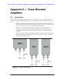
Appendix D—Tower Mounted Amplifiers
D-1 Introduction . . . . . . . . . . . . . . . . . . . . . . . . . . . . . . . . . . . . . . . . . . . . . . .D-1
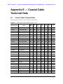
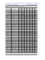
Appendix E—Coaxial Cable Technical Data
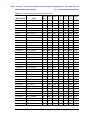
E-1 Coaxial Cable Technical Data. . . . . . . . . . . . . . . . . . . . . . . . . . . . . . . . . . . E-1
Appendix F—Waveguide Data
F-1 Introduction . . . . . . . . . . . . . . . . . . . . . . . . . . . . . . . . . . . . . . . . . . . . . . . . . F-1
F-2 Calibration Components . . . . . . . . . . . . . . . . . . . . . . . . . . . . . . . . . . . . . . . F-1
F-3 Waveguide-to-Coaxial Adapters . . . . . . . . . . . . . . . . . . . . . . . . . . . . . . . . . F-2
F-4 Flange Compatibility . . . . . . . . . . . . . . . . . . . . . . . . . . . . . . . . . . . . . . . . . F-3
Universal Flange Compatibility . . . . . . . . . . . . . . . . . . . . . . . . . . . . . . . F-4
Universal Flange Compatibility . . . . . . . . . . . . . . . . . . . . . . . . . . . . . . . F-6
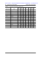
F-5 Waveguide Technical Data . . . . . . . . . . . . . . . . . . . . . . . . . . . . . . . . . . . . F-7
Waveguide Technical Data . . . . . . . . . . . . . . . . . . . . . . . . . . . . . . . . . . F-8
Appendix G—More About DHCP
G-1 Introduction . . . . . . . . . . . . . . . . . . . . . . . . . . . . . . . . . . . . . . . . . . . . . . . . .G-1
ООО "Техэнком" Контрольно-измерительные приборы и оборудование www.tehencom.com

MS20xxC UG PN: 10580-00305 Rev. J Contents-7
G-2 Ethernet Configuration . . . . . . . . . . . . . . . . . . . . . . . . . . . . . . . . . . . . . . . .G-1
LAN Connection . . . . . . . . . . . . . . . . . . . . . . . . . . . . . . . . . . . . . . . . . .G-1
Ethernet Config . . . . . . . . . . . . . . . . . . . . . . . . . . . . . . . . . . . . . . . . . . .G-3
Ethernet Menu . . . . . . . . . . . . . . . . . . . . . . . . . . . . . . . . . . . . . . . . . . .G-4
G-3 Using DHCP . . . . . . . . . . . . . . . . . . . . . . . . . . . . . . . . . . . . . . . . . . . . . . . .G-4
G-4 Static IP Address . . . . . . . . . . . . . . . . . . . . . . . . . . . . . . . . . . . . . . . . . . . .G-4
IP Address . . . . . . . . . . . . . . . . . . . . . . . . . . . . . . . . . . . . . . . . . . . . . . .G-5
Default Gateway . . . . . . . . . . . . . . . . . . . . . . . . . . . . . . . . . . . . . . . . . .G-5
Subnet Mask . . . . . . . . . . . . . . . . . . . . . . . . . . . . . . . . . . . . . . . . . . . . .G-5
Example 1 . . . . . . . . . . . . . . . . . . . . . . . . . . . . . . . . . . . . . . . . . . . . . . .G-5
Example 2 . . . . . . . . . . . . . . . . . . . . . . . . . . . . . . . . . . . . . . . . . . . . . . .G-5
G-5 Operating System Tools . . . . . . . . . . . . . . . . . . . . . . . . . . . . . . . . . . . . . . .G-5
Ipconfig Tool . . . . . . . . . . . . . . . . . . . . . . . . . . . . . . . . . . . . . . . . . . . . .G-6
Ping Tool . . . . . . . . . . . . . . . . . . . . . . . . . . . . . . . . . . . . . . . . . . . . . . . .G-6
Appendix H—Glossary of Terms
Glossary Terms . . . . . . . . . . . . . . . . . . . . . . . . . . . . . . . . . . . . . . . . . . . H-2
Index
ООО "Техэнком" Контрольно-измерительные приборы и оборудование www.tehencom.com

Contents-8 PN: 10580-00305 Rev. J MS20xxC UG
ООО "Техэнком" Контрольно-измерительные приборы и оборудование www.tehencom.com

MS20xxC UG PN: 10580-00305 Rev. J 1-1
Chapter 1 — General Information
1-1 Introduction
This chapter covers general information that includes a description, optional accessories,
preventive maintenance, ESD verifications, and calibration requirements for the
VNA Master model MS20xxC. Throughout this manual, the terms VNA Master and
MS20xxC refer to the Anritsu MS2026C, MS2027C, MS2028C, MS2036C, MS2037C, and
MS2038C Vector Network Analyzers.
MS2026C
VNA Frequency: 5 kHz to 6 GHz
MS2027C
VNA Frequency: 5 kHz to 15 GHz
MS2028C
VNA Frequency: 5 kHz to 20 GHz
MS2036C
VNA Frequency: 5 kHz to 6 GHz
SPA Frequency: 9 kHz to 9 GHz
MS2037C
VNA Frequency: 5 kHz to 15 GHz
SPA Frequency: 9 kHz to 15 GHz
MS2038C
VNA Frequency: 5 kHz to 20 GHz
SPA Frequency: 9 kHz to 20 GHz
1-2 Contacting Anritsu
To contact Anritsu, please visit:
http://www.anritsu.com/contact.asp
From here, you can select the latest sales, select service and support contact information in
your country or region, provide online feedback, complete a “Talk to Anritsu” form to have
your questions answered, or obtain other services offered by Anritsu.
Updated product information can be found on the Anritsu web site: http://www.anritsu.com/
Search for the product model number. The latest documentation is on the product page under
the Library tab.
http://www.anritsu.com/en-us/products-solutions/products/MS2026C.aspx
http://www.anritsu.com/en-us/products-solutions/products/MS2027C.aspx
http://www.anritsu.com/en-us/products-solutions/products/MS2028C.aspx
http://www.anritsu.com/en-us/products-solutions/products/MS2036C.aspx
http://www.anritsu.com/en-us/products-solutions/products/MS2037C.aspx
http://www.anritsu.com/en-us/products-solutions/products/MS2038C.aspx
ООО "Техэнком" Контрольно-измерительные приборы и оборудование www.tehencom.com

1-3 Anritsu Service Centers General Information
1-2 PN: 10580-00305 Rev. J MS20xxC UG
1-3 Anritsu Service Centers
For the latest service and sales information in your area, please visit the following URL:
http://www.anritsu.com/Contact.asp and choose a country for regional contact information.
1-4 Additional Documents
This user guide is specific to the VNA Master MS20xxC (models MS2026C, MS2027C,
MS2028C, MS2036C, MS2037C, and MS2038C). Additional instrument functions and
descriptions of optional measurement capabilities are described in measurement guides.
Refer to Appendix A, “Supplemental Documentation” for a list of measurement guides and their
Anritsu part numbers. Measurement guides are provided on the document disc that is
shipped with each instrument. Updated measurement guides are available for download (at
no charge) from the VNA Master product Web pages listed previously.
General and performance specifications, instrument options, standard accessories, and
optional accessories are described in the VNA Master Technical Data Sheet, Anritsu part
number 11410-00548.
1-5 VNA Master Specifications
General and performance specifications, instrument options, standard accessories, and
optional accessories are described in the VNA Master Technical Data Sheet, (Anritsu part
number 11410-00548). The technical data sheet is available on the Anritsu Web site:
http://www.anritsu.com
ООО "Техэнком" Контрольно-измерительные приборы и оборудование www.tehencom.com

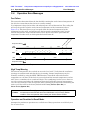
General Information 1-6 Identifying the Connections
MS20xxC UG PN: 10580-00305 Rev. J 1-3
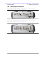
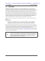
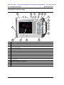
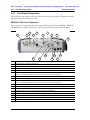
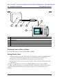
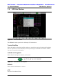
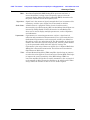
1-6 Identifying the Connections
The VNA Master MS2026C, MS2027C, and MS2028C have the connectors shown in
Figure 1-1.For details, refer to Figure 2-13 on page 2-20.
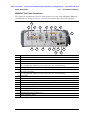
The VNA Master MS2036C, MS2037C, and MS2038C have the connectors shown in
Figure 1-2.For details, refer to Figure 2-14 on page 2-21
Figure 1-1. MS202xC Connectors
Figure 1-2. MS203xC Connectors
ООО "Техэнком" Контрольно-измерительные приборы и оборудование www.tehencom.com

1-7 Description General Information
1-4 PN: 10580-00305 Rev. J MS20xxC UG
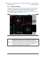
1-7 Description
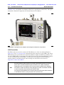
The Anritsu VNA Master instruments are portable handheld vector network analyzers
(VNAs) featuring precise performance and essential RF capabilities. These VNA Master
instruments are designed to conduct accurate vector-corrected 1-port magnitude, phase, and
fault location measurements and 2-port magnitude, phase, and group delay measurements
from 5 kHz to 20 GHz. The MS203xC models add Spectrum Analyzer capabilities that
provide quick and accurate measurement results for monitoring, measuring, and analyzing
signal environments. The Spectrum Analyzer offers broad spectrum analysis with frequency
coverage to 20 GHz, impressive dynamic range, and excellent phase noise performance.
Standard measurements include field strength, occupied bandwidth (OBW), channel power,
adjacent channel power ratio (ACPR), and carrier to interference (C/I) ratio.
This one instrument provides all essential RF capabilities in a portable, high-performance
platform.
Measurements:
S-parameters, magnitude, phase, real, imaginary, SWR, Cable Loss, group delay,
Smith Chart, time domain, distance domain, field strength, occupied bandwidth,
channel power, adjacent channel power ratio, carrier to interference (C/I) ratio.
Time and date stamping of measurement data is automatic. The internal memory provides
for the storage and recall of up to 1000 measurement setups and up to 1000 traces. External
storage can be used for bulk measurement storage. Measurements and setups can be stored
in a USB flash drive or transferred to a PC by using the included USB cable. Use
Line Sweep Tools (LST) for certain VNA measurements and Master Software Tools (MST) for
spectral analysis measurements (refer to Chapter 8, “Anritsu PC Software Tools” for a brief
overview of these software tools).
Note
Not all after-market USB drives are compatible with the VNA Master. Many drives
come with a second partition that contains proprietary firmware. This partition must
be removed. Only one partition is allowed. Refer to the individual manufacturer for
instructions on how to remove it. You might also try reformatting a drive that
contains a single partition using FAT32 format.
ООО "Техэнком" Контрольно-измерительные приборы и оборудование www.tehencom.com
Page is loading ...
Page is loading ...
Page is loading ...
Page is loading ...
Page is loading ...
Page is loading ...
Page is loading ...
Page is loading ...
Page is loading ...
Page is loading ...
Page is loading ...
Page is loading ...
Page is loading ...
Page is loading ...
Page is loading ...
Page is loading ...
Page is loading ...
Page is loading ...
Page is loading ...
Page is loading ...
Page is loading ...
Page is loading ...
Page is loading ...
Page is loading ...
Page is loading ...
Page is loading ...
Page is loading ...
Page is loading ...
Page is loading ...
Page is loading ...
Page is loading ...
Page is loading ...
Page is loading ...
Page is loading ...
Page is loading ...
Page is loading ...
Page is loading ...
Page is loading ...
Page is loading ...
Page is loading ...
Page is loading ...
Page is loading ...
Page is loading ...
Page is loading ...
Page is loading ...
Page is loading ...
Page is loading ...
Page is loading ...
Page is loading ...
Page is loading ...
Page is loading ...
Page is loading ...
Page is loading ...
Page is loading ...
Page is loading ...
Page is loading ...
Page is loading ...
Page is loading ...
Page is loading ...
Page is loading ...
Page is loading ...
Page is loading ...
Page is loading ...
Page is loading ...
Page is loading ...
Page is loading ...
Page is loading ...
Page is loading ...
Page is loading ...
Page is loading ...
Page is loading ...
Page is loading ...
Page is loading ...
Page is loading ...
Page is loading ...
Page is loading ...
Page is loading ...
Page is loading ...
Page is loading ...
Page is loading ...
Page is loading ...
Page is loading ...
Page is loading ...
Page is loading ...
Page is loading ...
Page is loading ...
Page is loading ...
Page is loading ...
Page is loading ...
Page is loading ...
Page is loading ...
Page is loading ...
Page is loading ...
Page is loading ...
Page is loading ...
Page is loading ...
Page is loading ...
Page is loading ...
Page is loading ...
Page is loading ...
Page is loading ...
Page is loading ...
Page is loading ...
Page is loading ...
Page is loading ...
Page is loading ...
Page is loading ...
Page is loading ...
Page is loading ...
Page is loading ...
Page is loading ...
Page is loading ...
Page is loading ...
Page is loading ...
Page is loading ...
Page is loading ...
Page is loading ...
Page is loading ...
Page is loading ...
Page is loading ...
Page is loading ...
Page is loading ...
Page is loading ...
Page is loading ...
Page is loading ...
Page is loading ...
Page is loading ...
Page is loading ...
Page is loading ...
Page is loading ...
Page is loading ...
Page is loading ...
Page is loading ...
Page is loading ...
Page is loading ...
Page is loading ...
Page is loading ...
Page is loading ...
Page is loading ...
Page is loading ...
Page is loading ...
Page is loading ...
Page is loading ...
Page is loading ...
-
 1
1
-
 2
2
-
 3
3
-
 4
4
-
 5
5
-
 6
6
-
 7
7
-
 8
8
-
 9
9
-
 10
10
-
 11
11
-
 12
12
-
 13
13
-
 14
14
-
 15
15
-
 16
16
-
 17
17
-
 18
18
-
 19
19
-
 20
20
-
 21
21
-
 22
22
-
 23
23
-
 24
24
-
 25
25
-
 26
26
-
 27
27
-
 28
28
-
 29
29
-
 30
30
-
 31
31
-
 32
32
-
 33
33
-
 34
34
-
 35
35
-
 36
36
-
 37
37
-
 38
38
-
 39
39
-
 40
40
-
 41
41
-
 42
42
-
 43
43
-
 44
44
-
 45
45
-
 46
46
-
 47
47
-
 48
48
-
 49
49
-
 50
50
-
 51
51
-
 52
52
-
 53
53
-
 54
54
-
 55
55
-
 56
56
-
 57
57
-
 58
58
-
 59
59
-
 60
60
-
 61
61
-
 62
62
-
 63
63
-
 64
64
-
 65
65
-
 66
66
-
 67
67
-
 68
68
-
 69
69
-
 70
70
-
 71
71
-
 72
72
-
 73
73
-
 74
74
-
 75
75
-
 76
76
-
 77
77
-
 78
78
-
 79
79
-
 80
80
-
 81
81
-
 82
82
-
 83
83
-
 84
84
-
 85
85
-
 86
86
-
 87
87
-
 88
88
-
 89
89
-
 90
90
-
 91
91
-
 92
92
-
 93
93
-
 94
94
-
 95
95
-
 96
96
-
 97
97
-
 98
98
-
 99
99
-
 100
100
-
 101
101
-
 102
102
-
 103
103
-
 104
104
-
 105
105
-
 106
106
-
 107
107
-
 108
108
-
 109
109
-
 110
110
-
 111
111
-
 112
112
-
 113
113
-
 114
114
-
 115
115
-
 116
116
-
 117
117
-
 118
118
-
 119
119
-
 120
120
-
 121
121
-
 122
122
-
 123
123
-
 124
124
-
 125
125
-
 126
126
-
 127
127
-
 128
128
-
 129
129
-
 130
130
-
 131
131
-
 132
132
-
 133
133
-
 134
134
-
 135
135
-
 136
136
-
 137
137
-
 138
138
-
 139
139
-
 140
140
-
 141
141
-
 142
142
-
 143
143
-
 144
144
-
 145
145
-
 146
146
-
 147
147
-
 148
148
-
 149
149
-
 150
150
-
 151
151
-
 152
152
-
 153
153
-
 154
154
-
 155
155
-
 156
156
-
 157
157
-
 158
158
-
 159
159
-
 160
160
-
 161
161
-
 162
162
-
 163
163
-
 164
164


Anritsu MS20xxC User manual
- Category
- Measuring, testing & control
- Type
- User manual
- This manual is also suitable for
Ask a question and I''ll find the answer in the document
Finding information in a document is now easier with AI
Related papers
-
Anritsu MP2110A BERTWave Operating instructions
-
-
-
-
-
Anritsu VNA Master MS2026C Maintenance Manual
-
-
-
-
Other documents
-
 Tetchair ST-F808LCD/вишня User manual
-
 China Electronics Technology Instruments AV3672 Series User manual
-
Seitron Chemist 900 Operating instructions
-
RocketFish RF-G1179 Quick setup guide
-
 RigExpert AA-55 ZOOM Software Manual
-
Wavetek SNA 23 User manual
-
 Andrew UltraSpan User and Installation Manual
-
 MFJ 4116P User manual
-
PICO PicoVNA 106 User guide
-
Promax AC-726 User manual


