
1
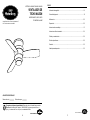
MAZON CEILING FAN
ITEM #0464467, 0464468, 0464469
MODEL #00873, 00874, 00875
ETL MODEL #44-MZ
Español p. 16
Serial Number
Purchase Date
Harbor Breeze ® is a registered trademark of LF,
LLC. All Rights Reserved.
Questions, problems, missing parts? Before returning to your retailer, call our customer
service department at 1-800-643-0067, 8 a.m. - 6 p.m., EST, Monday - Thursday,
8 a.m. - 5 p.m., EST, Friday.
ATTACH YOUR RECEIPT HERE
Lowes.com/harborbreeze
EB 14191

32
TABLE OF CONTENTS
Safety Information............................................................................................................... 3
Package Contents............................................................................................................... 4
Hardware Contents............................................................................................................. 5
Preparation.......................................................................................................................... 5
Assembly Instructions......................................................................................................... 6
Operating Instructions.......................................................................................................... 11
Care and Maintenance........................................................................................................ 13
Troubleshooting................................................................................................................... 14
Warranty.............................................................................................................................. 15
Replacement Parts List ...................................................................................................... 15
3
Lowes.com/harborbreezeLowes.com/harborbreeze
SAFETY INFORMATION
READ AND SAVE THESE INSTRUCTIONS
Please read and understand this entire manual before attempting to assemble, operate, or install
the product.
• When using an existing outlet box, be sure the box is securely attached to the building structure
and can support the full weight of the fan, so as to avoid potential serious injury or death.
• All wiring must be in accordance with the National Electrical Code “ANSI/NFPA 70-1999”
and local electrical codes. Electrical installation should be performed by a qualied licensed
electrician.
• DO NOT use bulbs with a wattage greater than the maximum value stated on the xture and in
this manual. Using a higher wattage bulb than specied will increase xture temperature and
cause risk of re.
• Disconnect the electrical supply circuit to the fan before installing light kit.
• Electrical diagrams are for reference only.
• The net weight of this fan including the light kit is: 15.62 lbs.
WARNING
• ELECTRIC SHOCK HAZARD - To reduce the risk of electric shock, do not use this fan with any
solid-state speed control device.
• ELECTRIC SHOCK HAZARD - To reduce the risk of electric shock, make sure electricity has
been turned off at the circuit breaker or fuse box before beginning installation.
• PERSONAL INJURY HAZARD - To reduce the risk of injury to persons, install fan so that the
blade is at least 7 ft. above the oor.
• ELECTRIC SHOCK HAZARD - Do not install this fan with wall-mounted solid-state speed
control or wall-mounted light-dimmer control. It will permanently damage the fan’s remote control
receiver and cause the fan’s functions to fail.
• FIRE, ELECTRIC SHOCK OR PERSONAL INJURY HAZARD - To reduce the risk of re,
electric shock, or personal injury, mount to outlet box marked “ACCEPTABLE FOR FAN
SUPPORT OF 35.1 lbs OR LESS” and use mounting screws provided with the outlet box. Most
outlet boxes commonly used for the support of lighting xtures are not acceptable for fan support
and may need to be replaced. Consult a qualied electrician if in doubt.
CAUTION
• PERSONAL INJURY HAZARD - Reduce the risk of personal injury, do not bend the blade
brackets when installing the brackets, balancing the blades, or cleaning the fan. DO NOT insert
foreign objects in between rotating fan blades.

54
PREPARATION
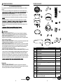
HARDWARE CONTENTS (shown actual size)
BB
N
AA
Wire Connector
Qty. 4
Blade Screw
Qty. 10
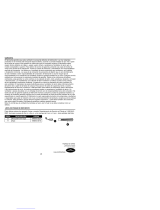
PACKAGE CONTENTS
B
A
F
G
H
D
I
J
K
L
M
PART DESCRIPTION QUANTITY
A Mounting Plate 1
B Fan Motor 1
C Trim Ring 1
D Blade 3
E Enhance Plate 3
F Light Plate 1
G Light Fixture 1
H Switch Housing Plate (preassembled to Fan Motor (B)) 1
I Bulb 1
J Glass 1
K Remote Control 1
L Battery 1
M Wall Bracket 1
E
C
Lowes.com/harborbreezeLowes.com/harborbreeze
Before beginning assembly of product, make sure all parts are present. Compare parts with package
contents list and hardware contents list. If any part is missing or damaged, do not attempt to assem-
ble the product.
Estimated Assembly Time: 45 minutes
Tools Required for Assembly (not included): Phillips screwdriver, step ladder, electrical tape, pliers,
wire cutters, wire strippers.
CC
Remote Control
Screw
Qty. 2
R
N Rubber Shipping Stabilizer Tab (preassembled to fan motor (B) 3

6 7
ASSEMBLY INSTRUCTIONS ASSEMBLY INSTRUCTIONS
1
4
5
3
6
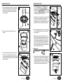
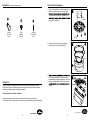
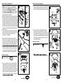
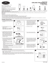
1. Attach mounting plate (A) to outlet box (not included)
using two screws (not included). Securely tighten two
outlet box screws. Pull black, white, and grounded
wires out of outlet box and through the hole in the
mounting plate (A).
2. Place trim ring (C) over canopy, and lay it on fan
motor (B).
3. Loosen two preassembled screws across from each
other on the mounting plate (A). Remove and save
remaining two preassembled screws. Hang fan motor (B)
on mounting plate (A) hook using one of the non-slotted
holes in the canopy.
4. Connect BLACK wire from fan to BLACK wire from
ceiling. Connect WHITE wire from fan WHITE wire
from ceiling. Connect all GROUNDED (GREEN) wires
together from fan GREEN/GROUNDED wire from ceiling.
Connecting the GREEN/GROUNDED wires is conducive
to receive the signal of the remote control.
Note: Black wire is hot power for fan and light kit. White
wire is common for fan and light kit. Green wire is
grounded wire. lf house wires are different colors
than referred to above, stop immediately and consult a
professional electrician to determine proper wiring.
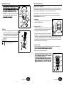
6. Align keyholes on fan motor (B) with protruding screw
heads on mounting plate (A). Lift fan motor (B) up to
mounting plate (A), making sure not to break any wire
connection. Rotate clockwise until screw heads fully
engage into keyholes. Insert previously removed screws
(Step 3, page 6) and securely tighten all screws.
A
A
B
B
B
A
C
B
Outlet box
Screw
2
Hardware Used
x 4
Wire Connector
AA
AA
Canopy
Canopy
Screw
Hook
Grounded/
Green
White
Black
outlet box
black
white
green
white
GREEN/
GROUNDED
black
Supply circuit
receiver
Screw
Lowes.com/harborbreezeLowes.com/harborbreeze
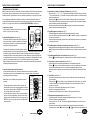
5. Twist wire ends together and screw wire connectors (AA)
on in a clockwise direction. Tape wire connectors (AA)
and wires together.
Note: Wires should be spread apart with grounded
conductor and equipment-grounding conductor on one
side of outlet box and ungrounded conductor on other
side. After making connections, make sure bare wire
or wire strands are NOT visible. Place green and white
connections on opposite side of box from black and
blue connections. Splices should be turned upward and
pushed carefully up into outlet box.
Black
Black
White
Green
Outlet box
Green/
Grounded
Receiver
White

8 9
ASSEMBLY INSTRUCTIONS
ASSEMBLY INSTRUCTIONS
11
9
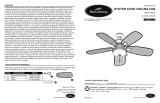
7. Align notches on fan motor (B) canopy with raised
areas on inside of trim ring (C). Pop trim ring (C) into
the canopy.
8. Remove and discard preassembled rubber shipping
stabilizer tabs (N) from fan motor (B). Insert blade
(D) into slot on fan motor (B). Secure blade (D) with
enhance plate (E) and three blade screws (BB). Repeat
for remaining blades (D), enhance plates (E) and blade
screws (BB).
10. Insert wires from fan motor (B) through middle hole in
light plate (F). Attach light plate (F) to switch housing
plate (H). Align keyholes then twist to lock. Replace
previously removed screw (Step 9, page 8) and
securely tighten all screws.
11. Loosen two preassembled screws from light plate (F).
Remove and save remaining preassembled screw
from light plate (F).
12. Connect WHITE wire from light plate (F) to WHITE
BLUE wire from
light plate (F) to BLACK
and twist to lock. Replace previously removed screw
(Step 11, page 9) and securely tighten all screws.
9. Loosen two screws from switch housing plate (H).
Remove and save remaining screw.
7
8
E
JJ
D
`
10
12
B
B
E
N
BB
D
H
C
KK
Screw
H
Canopy
Notch
Raised
area
Hardware Used
BB
N
Blade Screw x 10
Slot for
blade insert
Keyslot hole
Screw
Screw
Screw
B
F
F
F
G
Lowes.com/harborbreezeLowes.com/harborbreeze

1110
ASSEMBLY INSTRUCTIONS
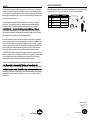
13.
CAUTION: Avoid touching the bulb with bare hands. Be
sure that the power is OFF and bulb is cool before
OPTIONAL:
14. If desired, wall bracket (M) can be installed to house
remote control (K). Remove small plate preassembled
on the wall bracket (M) and use remote control screws
(CC) to install wall bracket (M) to wall. Replace the
small plate, then place remote contral (K) into the wall
bracket (M).
13
J
Raised
dimples
Flat area
I
G
J
Lowes.com/harborbreezeLowes.com/harborbreeze
14
K
M
CC
Small plate
R
CC
Hardware Used
Remote Control Screw x 2
OPERATING INSTRUCTIONS
REMOTE CONTROL TRANSMITTER:
Note: The receiver is already wired and built into the fan canopy from the factory. Receiver assembly is not
needed. “Tap” refers to pressing a button on the remote for less than one second. “Press and hold” refers to
pressing a button and holding the button down for one second then release the button.
After fan installation is completed properly and power is turned on, the fan receiver will produce two
musical notes/sounds indicating that the power supply is normal. If no sounds are heard, please refer to
TROUBLESHOOTING section on page 14.
1. Install Battery:
Remove the battery cover from the remote control (K), and install
the battery (L). Replace the cover.
2. Learning/Pairing (See Fig. 1):
The dip switch in the remote control (K) has been set to “0” to match
the receiver in the fan. If there is more than one remote control in a
room, changing dip switch settings may be needed.
To change a dip switch setting, slide the switch inside the battery
compartment to “1”, turn off power to the fan, then turn on the power.
The fan receiver should make two musical notes/sounds indicating that the power supply is normal. Within
30 seconds of hearing notes/sounds, tap the “learn” key on the back of the remote control (K). If learning
is successful, the fan light will blink three times and turn on. Note: The fan will run at the highest speed in
corresponding direction per seasonal slide switch.
3. Season Slide Switch:
When the season changes, you may want to change the direction your fan spins. To switch between
Note: Wait for fan to stop before reversing switch.
• In warmer weather, counterclockwise rotation creates a downward
icon. Receiver will make 3 musical sounds.
•
which moves hot air from the ceiling into the room. Push the switch
sounds.
6 Speeds
Natural Breeze
Season Slide
Switch
Light On/Off
/Dimming
Walk Away
Light Delay
Fan on/off
Home Shield
Sleep Timer
K
2
1
Learn key
Dip switches
Open the battery
housing cover.
K
L
R
12V

12 13
Lowes.com/harborbreezeLowes.com/harborbreeze
Lowes.com/harborbreeze
CARE AND MAINTENANCE
• To reduce the risk of re, electric shock or injury to persons, care and maintain this fan.
• IMPORTANT: Shut off main power supply before beginning any maintenance.
• DO NOT use water or detergents when cleaning the fan or fan blades. A dry dust cloth or lightly
dampened cloth will be suitable for most cleaning.
• Clean fan housing with only a soft brush or lint-free cloth to avoid scratching the nish. Clean
blades with a lint-free cloth. You may occasionally apply a light coat of furniture polish to blades for
added protection.
• At least twice each year, tighten all screws and lower canopy to check mounting bracket screws
and downrod assembly.
• Bulb Replacement: Use 75-watt max. type-E11 halogen-base bulbs.
OPERATING INSTRUCTIONS
4. Fan Speeds: 6 speeds and Natural Breeze (See Fig. 2):
• Tap “1”, “2”, “3”, “4”, “5” or “6” key to switch fan to corresponding speed, “1” being the lowest and “6” being
the highest. The fan receiver will make a musical sound at each setting change.
• Tap “ ” key to enter Natural Breeze mode. Receiver will make
two musical sounds. Natural Breeze mode will simulate a natural breeze, like being outside.
(Fan blades will turn at different speeds randomly.)
• To exit Natural Breeze mode, tap “ ” then one of the numerical settings to shift to relative key function/
speed.
5. Fan On/Off (See Fig. 2):
• Fan On/Off controls power to the fan.
• When fan is on, tap “ ” key. Fan will turn off and receiver will produce two musical notes/sounds.
• When fan is off, tap “ ” key. Fan has memory and turns fan to most recent fan speed.
6. Musical Note/Sound Indicator On/Off (See Fig. 2):
• Press and hold “ ” key to turn the Musical Note/Sound indicator On or Off. Note: The receiver will
produce two musical notes/sounds each time the beep indicator is turned Off or On.
7. Light On/Off/Dimming (See Fig. 2):
• Tap “ ” to turn light on/off; press and hold for dimming.
8. Walk Away Light Delay (See Fig. 2):
• Using this button automatically turns off the light 1 minute after button is pressed.
• Tap “ ” once, light on ceiling fan blinks once to conrm Walk Away Light Delay is active, the light and
fan turn off after 1 minute.
• During Walk Away Light Delay mode, press any other key to cancel function.
9. Home Shield (See Fig. 2):
• Using this button will randomly turn lights on and off to give the illusion that someone is at home.
• Tap Home Shield button “ ”, light on ceiling fan blinks two times to conrm Home Shield is active. Fan is
off and the light will cycle through both A and B modes described below:
• A mode: Light randomly turns on for 5–20 minutes.
• B mode: Light is off for 60 minutes.
• During Home Shield mode, press any other key to cancel function.
10. Sleep Timer (See Fig. 2):
• Using these buttons will turn fan off automatically after a 2-hour, 4-hour, or 8-hour duration.
• Turn the fan on at the desired speed.
• Tap “2H”, “4H”, or “8H” key. The fan will turn off automatically after desired time has expired.
• Receiver will produce three musical notes/sounds. During Sleep Timer mode, tap “ ” key to exit sleep
timer mode. Tap “ ” or “ ” to also exit sleep timer and shift to relative key function.
11. Power Off Memory (See Fig. 2):
• Using this button resumes the settings used on the fan prior to the power being turned off.
• If the fan was in sleep timer mode before power is turned Off, fan will be off when power is turned back
On.
• If the fan is in the Walk Away Light Delay mode before power is turned Off, both the fan
and light will be off when power is turned back On.

REPLACEMENT PARTS LIST
For replacement parts, call our customer service department at 1-800-643-0067, 8 a.m. - 6 p.m., EST,
Monday - Thursday, 8 a.m. - 5 p.m., EST, Friday.
PART DESCRIPTION PART#
D Blade 108002-5060**
E Enhance Plate 104300-0018BK
J Glass 991300-0545AQ
K Remote Control 990319-011400
D
D
E
J
K
14
Lowes.com/harborbreezeLowes.com/harborbreeze
Printed in China
Harbor Breeze
®
is a registered
trademark of LF, LLC. All rights
reserved.
WARRANTY
The manufacturer warrants this fan to be free from defects in workmanship and material present at
time of shipment from the factory for lifetime limited from the date of purchase. This warranty applies
only to the original purchaser. The manufacturer agrees to correct such defect at no charge or at our
option replace the ceiling fan with a comparable or superior model.
To obtain warranty service, present a copy of your sales receipt as proof of purchase. All cost of
removal and reinstallation are the expressed responsibility of the purchaser. Any damage to the
ceiling fan by accident, misuse or improper installation, or by afxing accessories not produced by
the manufacturer of the fan, are at the purchaser’s own responsibility. The manufacturer assumes no
responsibility whatsoever for fan installation during the lifetime limited warranty. Any service
performed by an unauthorized person will render the warranty invalid.
Due to varying climatic conditions, this warranty does not cover changes in brass nish, rusting,
pitting, tarnishing, corroding or peeling. Brass nish fans maintain their beauty when protected from
varying weather conditions. Any glass provided with this fan is not covered by the warranty.
Any replacement of defective parts for the ceiling fan must be reported within the rst year from the
date of purchase. For the balance of the warranty, call our customer service department at
1-800-643-0067 for return authorization and shipping instructions so that we may repair or replace
the ceiling fan. Any fan or parts returned improperly packaged is the sole responsibility of the
purchaser. There is no further expressed warranty. The manufacturer disclaims any and all implied
warranties.
The duration of any implied warranty which can not be disclaimed is limited to the lifetime limited
period as specied in our warranty. The manufacturer shall not be liable for incidental, consequential
or special damages arising at or in connection with product use or performance except as may
otherwise be accorded by law. This warranty gives you specic legal rights and you also have other
rights which vary from state to state. This warranty supersedes all prior warranties.
Note: A small amount of “wobble” is normal and should not be considered a defect.
TROUBLESHOOTING
PROBLEM POSSIBLE CAUSE CORRECTIVE ACTION
Fan blades do not
move.
1. Power is off or fuse
is blown.
1. Turn power on or check fuse.
2. Turn power off. Loosen motor housing; check all
connections.
Noisy operation. 1. Blades are loose.
2. Cracked blade.
1. Tighten all blade screws.
2. Replace blades (call customer service).
Excessive wobbling. 1. Blades are loose.
2. Unbalanced blades.
3. Fan not securely
mounted.
1. Tighten all blade screws.
2. Use balance kit.
3. Turn power off. Carefully loosen canopy and
remount securely.
Remote control
malfunction.
1. No sound after fan
power is on.
2. No ash on
transmitter LED.
3. The remote control
does not work.
1. Please check if the power supply is connected
properly and main power is on.
2. Please check if the battery is installed into the
remote control. Make sure the battery is installed
properly. One side of the battery is positive and the
other is negative.
3. Try to Pair the remote control to the receiver
following these steps: Turn the power to the fan off,
then turn the power to the fan on and you should
hear the fan receiver produce two musical notes/
sounds indicating that the power supply is normal.
Within 30 seconds of hearing the two sounds, tap
the “learn” key at the back of the transmitter. The
Indication of a successful learning process: Light
(if installed) will blink 3 times and turn On, fan is in
highest speed in corresponding direction per the
seasonal slide switch.
15
Lowes.com/harborbreezeLowes.com/harborbreeze
R
Page is loading ...
Page is loading ...
Page is loading ...
Page is loading ...
Page is loading ...
Page is loading ...
Page is loading ...
Page is loading ...
-
 1
1
-
 2
2
-
 3
3
-
 4
4
-
 5
5
-
 6
6
-
 7
7
-
 8
8
-
 9
9
-
 10
10
-
 11
11
-
 12
12
-
 13
13
-
 14
14
-
 15
15
-
 16
16


Harbor Breeze 873 User manual
- Category
- Household fans
- Type
- User manual
Ask a question and I''ll find the answer in the document
Finding information in a document is now easier with AI
in other languages
- español: Harbor Breeze 873 Manual de usuario
Related papers
-
 Harbor Breeze 857 User manual
-
 Harbor Breeze SARATOGA 00798 User manual
-
 Harbor Breeze CPW1413 User manual
-
 Harbor Breeze OCEANSIDE 00834 User manual
-
 Harbor Breeze 40843 Installation guide
-
Harbor Breeze 0429784 Installation guide
-
Harbor Breeze CENTREVILLE 40117 Installation guide
-
 Harbor Breeze 00878 Installation guide
-
Harbor Breeze 40706 Installation guide
-
 Harbor Breeze ARMITAGE CC52WW5C Installation guide


Other documents
-
Fanimation LP8221LCH Owner's manual
-
-
-
 LF Harbor Breeze 00852 User manual
-
Allen + Roth SFL11BNK Installation guide
-
 Style Selections CLL11BNK Installation guide
-
-
-
Project Source CLL56-2WW Installation guide
-

