Page is loading ...

1
LAKE CYPRESS CEILING FAN
ITEM #0747615
MODE
L #CPW1413
Español p. 20
Serial Number
Purchase Date
Questions, problems, missing parts? Before returning to your retailer, call our customer
service department at 1-800-643-0067, 8 a.m. - 6 p.m., EST, Monday - Thursday,
8 a.m. - 5 p.m., EST, Friday.
AB15776
ATTACH YOUR RECEIPT HERE
Lowes.com/harborbreeze
Harbor Breeze
®
is a registered trademark
of LF, LLC. All Rights Reserved.

2
TABLE OF CONTENTS
Package Contents...............................................................................................................
Hardware Contents.............................................................................................................
Safety Information...............................................................................................................
Preparation .........................................................................................................................
Initial Installation Instructions...............................................................................................
Wiring Instructions................................................................................................................
Final Installation Instructions................................................................................................
Operating Instructions..........................................................................................................
Care and Maintenance .......................................................................................................
Troubleshooting...................................................................................................................
Limited Lifetime Warranty....................................................................................................
Replacement Parts List ......................................................................................................
3
4
4
5
6
9
12
15
16
16
18
19
Lowes.com/harborbreeze

3
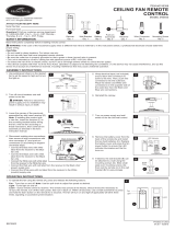
PACKAGE CONTENTS
PART DESCRIPTION QUANTITY
A Mounting Bracket 1
B Downrod Assembly 1
C Canopy 1
D
Canopy Cover
(preassembled on
Canopy (C))
1
E Coupling Cover 1
F Motor Housing 1
G
Blade Holder
5
H Blade 5
I Switch Housing 1
PART DESCRIPTION QUANTITY
J
Light Kit 1
K Glass Assembly
1
L Bulb 3
M
Power Kit
1
N Balance Kit 1
O
Clevis Pin
(preassembled on
Motor Housing (F))
1
Lowes.com/harborbreeze
P
Hairpin Clip
(preassembled on
Motor Housing (F))
1
Q
Coupling Screw
(preassembled on
Motor Housing (F))
2
G
H
J
K
L
M
ON D IP
4321
F
A
D
C
E
B
I
N
P
O
Q

4
HARDWARE CONTENTS
AA BB
SAFETY INFORMATION
READ AND SAVE THESE INSTRUCTIONS
Please read and understand this entire manual before attempting to assemble, operate or install the
product.
All electrical connections must comply with local codes, ordinances or the National Electric Code
(NEC). Contact your municipal building department to inquire about your local codes, permits and/or
inspections.
Turn off electricity at the main fuse box (or circuit breaker box) before beginning installation by
removing the fuse or by switching off the circuit breaker.
Do not connect this
to an electrical system that does not provide a means for equipment
grounding. Never use a
in a two-wire system that is not grounded.
If you are not sure your lighting system has a grounding means, do not attempt to install this
Contact a
licensed electrician for information regarding proper grounding methods as
required by the local electrical code in your area.
Make sure the installation site you choose allows a minimum clearance of 7 ft. from the blades to the
and at least 30 in. from the ends of the blades to any obstruction.
Secure the outlet box directly to the building structure. The outlet box and its support must be able to
support the moving weight of the fan (at least 35 Ibs.).
If a dimmer control switch is used with this
obtain professional advice to determine the correct
type and electrical rating required.
The lighting
must be positioned so there is at least 1.64 ft. between the bulb and any illuminated
surface.
For supply connections, if the conductor of a fan is
as a grounded conductor, then it should
be connected to a grounded conductor power supply. If the conductor of a fan is
as an
ungrounded conductor, then it should be connected to an ungrounded conductor power supply. If the
conductor of a fan is
for equipment grounding, then it should be connected to an equipment-
grounding conductor.
All
must be mounted to a 4 in. x 4 in. x 2-1/8 in. deep metal outlet box that is supported by
the building structure. Do not attempt to support the
by ceiling board alone. The ceiling board
alone does not have the strength to support the weight of the
The could fall and cause
personal injury.
Do not use bulbs having a wattage greater than the maximum value stated on the
and in this
manual. Using a higher wattage bulb than
will increase temperature and increase
risk of
CAUTION
Lowes.com/harborbreeze
Blade Screw
Qty. 15 + 1 Extra
Motor Screw
Qty. 10 (5 preassembled) + 1 Extra

5
WARNING
DANGER
Risk of Most dwellings built before 1985 have supply wire rated for 140°F. Consult a
elec
trician before installation.
Wire connectors will not support the weight of a
suspending a by the house wires and
wire connectors will result in the
falling, with the possibility of personal injury and the danger
of electrical shock or
To reduce the risk of
or electric shock, do not use this fan with any solid state fan speed device or
variable speed control.
To reduce the risk of personal injury, do not bend the blade brackets when installing the brackets,
balancing or cleaning the fan.
Do not insert foreign objects in between rotating fan blades.
Do not install or use the fan if any part is damaged or missing.
To reduce the risk of
electrical shock or personal injury, mount to outlet box marked “ACCEPTABLE
FOR FAN SUPPORT OF 35 LBS OR LESS” and use mounting screws provided with the outlet box
and/or support directly from building structure. Most outlet boxes commonly used for the support
of luminaries are not acceptable for fan support and may need to be replaced. Consult a
electrician if in doubt.
Before servicing or cleaning the unit, switch power off at the service panel and lock the service
disconnecting means to prevent power from being switched on accidentally. When the service
disconnecting means cannot be locked, securely fasten a prominent warning device, such as a tag,
to the service panel.
Installing a
into an electrical system without a proper grounding means could allow metal parts
of the
to carry electrical currents. If any of the wires, wire connections or splices are
broken, cut or loose during the mounting or normal operation of the
under such condition,
anyone coming in contact with the
is subject to electrical shock, which could cause serious
injury or death.
Connection of the bare or green
ground wire to the black or white house wires may allow metal
parts of the
to carry electrical currents. Under this condition anyone coming in contact with the
will receive electrical shock, which could cause serious injury or death.
Be careful not to damage or cut the wire insulation (covering) during
installation. Do not permit
wires to have contact with any surface having a sharp edge. Doing so may damage or cut the wire
insulation, which could cause serious injury or death from electric shock.
PREPARATION
Before beginning assembly of product, make sure all parts are present. Compare parts with package
contents list and hardware contents list. If any part is missing or damaged, do not attempt to assemble
the product.
Estimated Assembly Time: 45 minutes
Tools Required for Assembly (not included): Philips Screwdriver, Step Ladder, Tape, Pliers and
Wire Cutters.
Lowes.com/harborbreeze

6
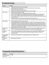
INITIAL INSTALLATION INSTRUCTIONS
1. Turn off circuit breakers and wall switch to the fan
supply line leads.
2.
Choose the desired mounting method:
3. Check existing outlet box (not included) to ensure it is
securely fastened to at least two points in a structural
ceiling member and can support the full weight of
)A( tekcarb gnitnuom llatsni ,deifirev ecnO .naf eht
to
the outlet box using the screws and washers provided
with the outlet box.
Note: If using the angle mount, make sure open end
of mounting bracket (A) points toward the ceiling.
DANGER:
Failure to disconnect power supply
prior to installation may result in serious injury or
death.
DANGER: A loose outlet box can cause the
fan to wobble and increase the fan’s potential to fall,
which could result in serious injury or death.
A. Standard Mounting:
Standard mounting is best suited for ceilings 8 feet.
or higher. For taller ceilings you may want to use a
longer downrod (not included).
B.
C.
Angle Mounting:
Angle-style mounting is best suited for angled or
vaulted ceilings. A longer downrod is sometimes
necessary to ensure proper blade clearance. If
using the angle mount, make sure the ceiling angle
is not steeper than 20°.
Flush Mounting:
Flushmount installation is used for ceilings less
than 8 feet high.
Lowes.com/harborbreeze
A
B
C
2
3
Standard/Flush
Mounting
A
Angle
Mounting
A
For ALL mounting options, there must be at least
30 inches from the blade tip to nearest wall. Also,
ensure there is 7 feet from the bottom edge of the
blade to the floor.
or
T
Turn Off Power Source
1

7
4. Remove hairpin clip (P) and clevis pin (O) from the
coupling in motor housing (F). Retain for later use.
Loosen the two coupling screws (Q), but do not
remove them.
Note: Make sure to keep loose hardware separate to
avoid confusion during installation.
For STANDARD/ANGLE-MOUNTING
INSTRUCTIONS, proceed to step 1 below.
For FLUSHMOUNT INSTRUCTIONS, skip to page 8.
1. Insert downrod assembly (B) through canopy (C),
canopy cover (D) and coupling cover (E).
2. Feed power wires from motor housing (F) through
(B) into the coupling on motor housing (F).
INITIAL INSTALLATION INSTRUCTIONS
STANDARD/ANGLE-MOUNTING INSTRUCTIONS
F
O
P
Coupling
Q
4
Note: Motor wires have been
omitted from diagram.
D
C
E
B
1
Lowes.com/harborbreeze
WARNING: Ensure all screws are tight before
moving on to the next step.
2
F
B
P
O
Q
Coupling
downrod assembly (B), then insert downrod assembly
Align the hole on downrod assembly (B) to the hole on
the
coupling, then re-install clevis pin (O). Re-attach
hairpin clip (P) into clevis pin (O) until it snaps into
place, then tighten the two previously loosened
coupling screws (Q).

8
3. Cut off excess
wires approximately 6 to 9
inches above top of the downrod assembly (B).
Strip insulation off 1/2 in. from the end of each
wire.
STANDARD/ANGLE-MOUNTING INSTRUCTIONS
FLUSHMOUNT INSTRUCTIONS
Lowes.com/harborbreeze
3
6 to 9 in.
4. Carefully lift the fan and place the hanger ball of
downrod assembly (B) in the mounting bracket (A)
attached to the outlet box.
1. Remove canopy cover (D) by pressing out on the inner
edges until it releases from the canopy (C).
NOTE: Be sure the slot in the hanger ball is lined up
with the tab on the mounting bracket (A).
DANGER: Be careful when aligning the tab to the
slot! If not fully engaged, there is a possiblity of the
fan falling, which may result in serious injury or death.
Proceed to WIRING on page 10.
Tab
A
Slot
4
1
C
D

9
FLUSHMOUNT INSTRUCTIONS
Lowes.com/harborbreeze
2.
Remove the three preassembled Phillips screws
near the coupling on the motor housing (F). Save them
for future use. Guide motor wires through the base of the
canopy (C), then attach canopy (C) to motor housing (F)
with previously removed screws. Tighten securely.
3. Raise assembly and temporarily place one side of
canopy (C) onto hook of mounting bracket (A). This will
allow for hands-free wiring.
Proceed to WIRING on page 10.
3
C
F
2
Screws
Coupling

10
1. To sync the remote from power kit (M) to the receiver
also in power kit (M),
remove the battery
cover from the remote and slide code switches to
your choice of up or down position using a small
screwdriver or ballpoint pen (neither included).
Note: The factory setting for the code switches is
all up; do not use this position.
WIRING INSTRUCTIONS
WARNING: To avoid possible electrical shock, be sure electricity is turned off at the main fuse
box before hanging.
WARNING: If house wires are of different colors than referred to in the following steps, stop
immediately. A professional electrician is recommended to determine proper wiring.
Note: If you are not sure if the outlet box is grounded, contact a licensed electrician for advice, as it
must be grounded for safe operation.
Note: The remote from power kit (M) has 16 different code combinations. To prevent possible
interference from or to other remote units, simply change the combination code in your remote and
receiver as described in Step 1 below.
ON
1 2 3 4
DIP
DIP
ON
1
Remote
Receiver
Lowes.com/harborbreeze
2. Slide the receiver from the power kit (M) into the open
end of the mounting bracket (A) with the
side of
the receiver facing the ceiling.
A
Receiver
2
Slide the code switches on the receiver to the same
positions, then replace battery cover on the remote.

WIRING INSTRUCTIONS
3. Make wire connections as follows:
Connect WHITE wire from the fan to WHITE wire
from receiver from the power kit (M) marked
TO MOTOR N using a wire connector from
power kit (M).
Connect BLACK wire from fan to BLACK wire
from receiver from the power kit (M) marked TO
MOTOR L
using a wire connector from power
kit (M).
Connect BLUE wire from the fan to BLUE wire
from receiver from the power kit (M) marked
“FOR
LIGHT” using a wire connector from
power
kit (M).
Connect BLACK wire from outlet box to RED
wire from receiver from the power kit (M)
marked
AC IN L using a wire connector from
power
kit (M).
WHITE wire from outlet box to WHITE
wire from receiver from the power kit (M)
marked
AC IN N using a wire connector from
power
kit (M).
Connect the GREEN wires from outlet box to the
GREEN wires from fan and mounting bracket (A)
using a wire connector from power kit (M).
11
Lowes.com/harborbreeze
4. Wrap electrical tape (not included) around each
wire connector and make sure no bare wire or wire
strands are visible after making connections.
Then, turn wires upward and carefully push them
dna ETIHW eht erus ekam ;xob teltuo eht otni
GREEN connections are on one side and the BLACK
connections are on the other side.
Green
(ground wire)
Black
White
4
Blue
Green
Black
Blue
3
White
Red
White
Green
White
Black
Green
A
Receiver
Listed Outlet Box

NOTE: Flushmount installation will not use the downrod
assembly (B), canopy cover (D) or coupling cover (E).
1. Loosen (but do not remove) the two mounting bracket
screws preassembled on mounting bracket (A) that align
with the slotted holes on canopy (C). Remove the other
two mounting bracket screws. Lift canopy (C) up so
slotted holes engage loosened screw heads on mounting
bracket (A), then twist canopy (C) clockwise. Re-install
previously removed mounting bracket screws, then
tighten all screws securely.
Note: If the canopy cover (D) is loose during installation,
please press it to the inner edge of the canopy (C).
FINAL INSTALLATION INSTRUCTIONS
2. Position one blade holder (G) under blade (H). Insert
three blade screws (AA) through blade (H) and into
blade holder (G). Tighten each blade screw (AA) evenly,
starting with the center screw.
Repeat for the remaining blade assemblies.
Hardware Used
Blade Screw
x 15
AA
Hardware Used
Motor Screw
x 10
12
Lowes.com/harborbreeze
G
H
AA
2
3. If present, remove and discard the preassembled plastic
motor blocks but remain the motor screws (BB) from
motor housing (F). Position one completed blade
assembly under motor housing (F), aligning the holes in
blade holder (G) with those in motor housing (F). Secure
blade assembly using motor screws (BB), tightening by
hand only.
Repeat this step for the remaining blade assemblies.
BB
C
A
Screw
C
A
Screw
1
D
3
BB
Shipping Block BB
F
G
BB

FINAL INSTALLATION INSTRUCTIONS
4. Remove one of the screws preassembled on
mounting plate of motor housing (F) and loosen but
do not remove the
other two. Insert the wires from the
motor housing
(F) through the middle hole in the switch
housing
(I). Attach the switch housing (I) to the mounting
plate by placing the keyslot holes of the switch
housing (I) onto the two protruding screw heads on
the mounting plate. Twist the switch housing (I)
until the screws engage the keyslots, then install the
previously removed screw into the closed hole in
the switch housing (I). Tighten all screws to secure
switch housing (I) to mounting plate.
5.
Connect the 2 single-pin connectors from the motor
housing (F) to the 2 single-pin connectors from the
light
kit (J)
- W
HITE to WHITE and BLACK to BLACK.
Remove one of the screws from the switch
housing (I)
and loosen but do not remove the other
two.
Attach the
light kit (J) to the switch housing (I)
by placing
the keyslot
holes from the light kit (J) onto the two protruding screws
on the switch housing (I)
. Twist the light kit (J) until the
screws engage the keyslots, then
install the previously
removed screw into the closed hole in the light kit (J).
Tighten all screws to secure light kit (J) to switch housing
(I).
13
6. Install bulbs (L) into each socket on the light kit (J) .
CAUTION: An energy-saving wattage limiter is
included in the receiver from the power kit (M). When
replacing bulbs, ensure bulb wattage is less than 190
watts, otherwise the item will either dim the lights to
190 watts or will automatically turn off.
Mounting
Plate
Screw
4
I
J
5
Lowes.com/harborbreeze
L
6
J
F
I

FINAL INSTALLATION INSTRUCTIONS
14
7.
Raise the glass assembly (K) up to the switch housing
(I), aligning the keyholes on glass assembly (K) with the
3 pressembled screws on the switch housing (I). Rotate
the glass assembly (K) clockwise until the screws drop
into the slot recesses.
Lowes.com/harborbreeze
7
K
I
8.
OPTIONAL: A wall bracket for the remote is included
with power kit (M). Use the screws provided in the
power kit (M) to attach the wall bracket to the desired
installation site. Once secure, store the remote inside
the wall bracket.
8
R
Wall bracket
Screw

15
OPERATING INSTRUCTIONS
Note:
3. When the season changes, you may want to change
the direction in which the fan spins.
In warmer weather, counterclockwise rotation creates
a downward which cools the air. Push the
switch L
EFT and see a SUN icon.
In cooler weather, clockwise rotation creates an
upward which moves hot air from the ceiling.
Push the switch RIGHT and see a SNOWFLAKE icon.
the reverse switch.
Use a small screwdriver or ballpoint pen to
move the reverse switch if you have
doing
so by hand.
3
Lowes.com/harborbreeze
2. The buttons on the remote from the power kit (M)
control the fan speed and light as follows:
Note: This receiver has a preset memory function;when
the switch is turned OFF, the control will remember the
light intensity and fan speed. When the switch is turned
back ON, the light and fan will resume operation as they
were prior to the switch being turned OFF.
Low speed
Medium speed
High speed
Turn the fan off
Press the light key quickly and turn the light ON or OFF.
Press and hold to dim the light.
The light will cycle from bright to dim to bright until
button is released.
R
2
1.
Remove battery door from the remote in the power
kit (M) and insert battery also from power
kit (M).
Ensure the polarity of the battery matches the
polarity
indicated in the battery compartment of
remote, then
replace battery door.
CAUTION: If you are not expecting to use the
remote for a long period of time, remove the battery
to prevent damage to the remote. Be sure to store the
remote away from excess heat or humidity.
ON
DIP
Battery Door
Remote
Battery
1

16
CARE AND MAINTENANCE
IMPORTANT: Shut off main power supply before beginning any maintenance. Do not use water
or a damp cloth to clean the ceiling fan.
At least twice each year, tighten all screws and lower canopy to check mounting plate screws.
Clean fan housing with only a soft brush or lint-free cloth to avoid scratching the
Clean
blades with a lint-free cloth. You may occasionally apply a light coat of furniture polish to wood
blades for added protection.
Bulb Replacement: Use three 40-watt max. type-A15 incandescent bulbs. CFLs and LEDs bulbs
Battery Replacement: Use one 23A 12-volt battery.
TROUBLESHOOTING
PROBLEM POSSIBLE CAUSE CORRECTIVE ACTION
Fan sounds noisy. 1. Set screws are loose.
2. Using non-approved speed control.
3. Normal noise.
4. Wire connectors inside switch
housing rattling.
5. Cracked blade.
6. Faulty light bulb installation.
7. Glass is not secure.
1. Tighten all set screws.
2.
Some fan motors are sensitive to
signals from solid-state variable
speed controls. DO NOT USE a
solid-state variable speed control.
3. Allow “break-in”
period of 24
hours. Most noises associated
with a new fan will disappear after
this period.
4. Check to make sure wire
connectors in switch housing are
not rattling against each other
or against the interior wall of the
switch housing.
5. Replace blade.
6. Make sure light bulb is tight in
socket and does not touch the
glass shade.
7. Secure the glass.
Fan wobbles. 1. Hanger bracket and/or ceiling outlet
box is not securely fastened.
2. Set screw in downrod assembly is
loose.
3. Fan hanger ball is not properly
seated in canopy tabs.
1. Tighten the hanger bracket
screws to the outlet box, and/or
secure outlet box.
2. Tighten the set screw in the
downrod assembly.
3. Turn power off, support the fan
very carefully, and check that the
hanger ball is properly seated.
Lowes.com/harborbreeze
are not recommended for this item.
4. Set screw in motor coupling is
loose.
4.
Raise motor coupling up and
tighten set screws securely.

17
TROUBLESHOOTING
PROBLEM POSSIBLE CAUSE CORRECTIVE ACTION
Fan wobbles.
5. Blades are loose.
6. Blade holders are loose.
7. Fan blade out of balance.
8. Fan too close to vaulted ceiling.
9. Transition to different speed.
10. Fan not securely mounted.
5. Check that all blades are screwed
into blade holders.
6. Check to be sure the fan blade
seat and uniformly
on the surface of the motor hub.
If
are seated incorrectly,
loosen the
screws and
retighten.
7. Interchange two adjacent blades;
this will redistribute the weight
and possibly result in smoother
operation. Or, refer to the
instructions inside the balance
kit (N).
8. Lower or move fan. Extension
downrods may be ordered.
9. When switching from medium to
low speed, you may notice some
fan wobble in the fan. When
the fan stabilizes at low speed,
wobble will disappear.
10. Make sure canopy and mounting
bracket are tightened securely to
ceiling joist.
Fan does not start. 1. Power turned off, fuse blown or
circuit breaker tripped.
2. Loose wire connections or wrong
connections.
3. Motor reversing switch not
engaged.
4. The dip switches from the remote
and receiver are not set to the
same frequency.
5. Batteries do not work.
1. Turn power on, replace fuse or
reset breaker.
2a. Turn power off and loosen
canopy; check all connections
according to section WIRING
INSTRUCTIONS on page
10 to 11.
2b. Check the plug connection in the
switch housing.
3. Push switch
right or
left.
Fan will not operate when switch
is in the middle.
4. Check to make sure the dip
switches from the remote and
receiver are set to the same
frequency.
5a. Make sure the batteries are
installed properly into the remote.
5b. Replace old battery with new one.
Lowes.com/harborbreeze

18
TROUBLESHOOTING
PROBLEM POSSIBLE CAUSE CORRECTIVE ACTION
Light does not
work.
1. Wrong wire connection.
2. Light bulb is burned out.
1. Refer to Step 3, page 11 to
ensure all wire connections were
done correctly.
2. Replace the bulbs.
LIMITED LIFETIME WARRANTY
The manufacturer warrants this fan to be free from defects in workmanship and material present at time
of shipment from the factory for life (with limitations) from the date of purchase. This warranty applies
only to the original purchaser. The manufacturer agrees to correct such defect at no charge or, at our
option, replace the ceiling fan with a comparable or superior model.
To obtain warranty service, present a copy of your sales receipt as proof of purchase. All cost of removal
and reinstallation are the expressed responsibility of the purchaser. Any damage to the ceiling fan by
accident, misuse or improper installation, or by
accessories not produced by this warranty, are
at the purchaser’s own responsibility. The manufacturer assumes no responsibility whatsoever for fan
installation during the limited lifetime warranty. Any service performed by an unauthorized person will
render the warranty invalid.
Due to varying climatic conditions, this warranty does not cover changes in brass
rusting, pitting,
tarnishing, corroding or peeling. Brass
fans maintain their beauty when protected from varying
weather conditions.
Any replacement of defective parts for the ceiling fan must be reported within the
year from the date
of purchase. For the balance of the warranty, call our customer service department at 1-800-643-0067
for return authorization and shipping instructions so that we may repair or replace the ceiling fan. Any
fan or parts returned improperly packaged is the sole responsibility of the purchaser. There is no further
expressed warranty. The manufacturer disclaims any and all implied warranties.
The duration of any implied warranty which can not be disclaimed is limited to the lifetime limited period
as
in our warranty. The manufacturer shall not be liable for incidental, consequential or special
damages arising at or in connection with product use or performance except as may other wise be
accorded by law. This warranty gives you
legal rights, and you also have other rights which vary
from state to state. This warranty supersedes all prior warranties.
Note: A small amount of “wobble” is normal and should not be considered a defect.
Lowes.com/harborbreeze

19
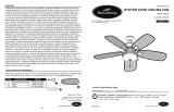
REPLACEMENT PARTS LIST
For replacement parts, call our customer service department at 1-800-643-0067, 8 a.m. - 6 p.m., EST,
Monday - Thursday, 8 a.m. - 5 p.m., EST, Friday.
PART DESCRIPTION PART #
A Mounting Bracket A102-0282005
B Downrod Assembly A103-0328390
C Canopy A101-0348390
D Canopy Cover A108-0260348
E Coupling Cover A106-1262390
G Blade Holder A143-0352390
H Blade A141-0436001
I Switch Housing A121-0328390
PART DESCRIPTION PART #
J Light Kit A187-0386003
K Glass Bowl A182-0378390
M
Remote
A137-0303036
Receiver
AA Blade Screw B166-0256005
BB Motor Screw B166-0487018
Print
ed in China
Lowes.com/harborbreeze
Harbor Breeze is a registered trademark
®
F, LLC.All Rights Reserved.
G
H
J
K
M
ON D IP
4321
A
D
C
E
R
B
I
AA
BB
/