Page is loading ...

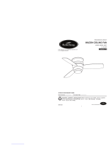
ITEM #0020776
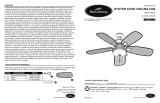
ARMITAGE CEILING FAN
MODEL #CC52WW5C
Harbor Breeze® is a registered trademark of
LF, LLC. All Rights Reserved.
Español p. 18
1
ATTACH YOUR RECEIPT HERE
Serial Number Purchase Date
Lowes.com/harborbreeze
EB15412
Questions, problems, missing parts? Before returning to your retailer, call our customer
service department at 1-800-643-0067, 8 a.m. - 6 p.m., EST, Monday - Thursday, 8 a.m. -
5 p.m., EST, Friday.
4010239

2
TABLE OF CONTENTS
SAFETY INFORMATION
READ AND SAVE THESE INSTRUCTIONS
Please read and understand this entire manual before attempting to assemble, install or operate the
product.
• Do not discard fan carton or foam inserts. Should this fan need to be returned to the factory for
repairs, it must be shipped in its original packaging to ensure proper protection against damage that
might exceed the initial cause for return.
• Make sure all electrical connections comply with local codes, ordinances, the National Electrical
Code and ANSI/NFPA 70-1999. Hire a qualified electrician or consult a do-it-yourself wiring
handbook, available at Lowe's, if you are unfamiliar with installing electrical wiring.
• Make sure the installation site you choose allows a minimum clearance of 7 ft. from the blades to the
floor and at least 30 in. from the end of the blades to any obstruction.
• After you install the fan, make sure all connections are secure to prevent the fan from falling.
• The net weight of this fan including the light kit is: 14.11 lbs.
Lowes.com/harborbreeze
Safety Information ...............................................................................................................2
Package Contents ...............................................................................................................4
Hardware Contents
..........................................................................................................................
5
Preparation ..........................................................................................................................5
Initial Installation ..................................................................................................................6
Wiring ..................................................................................................................................8
Final Installation ................................................................................................................10
Operating Instructions .......................................................................................................12
Care and Maintenance ......................................................................................................14
Troubleshooting..................................................................................................................15
Limited Lifetime Warranty ..................................................................................................16
Replacement Parts List .....................................................................................................17

3Lowes.com/harborbreeze
SAFETY INFORMATION
To reduce the risk of fire, electrical shock or personal injury, mount fan to outlet box
marked "ACCEPTABLE FOR FAN SUPPORT OF 35 LBS. (15.9 KG) OR LESS" and use
mounting screws provided with the outlet box. Most outlet boxes commonly used for the
support of lighting fixtures are not acceptable for fan support and may need to be replaced.
Consult a qualified electrician if in doubt.
When mounting fan to a ceiling outlet box, use a METAL octagonal outlet box; do NOT use a
plastic outlet box. Secure the outlet box directly to the building structure. The outlet box and its
support must be able to support the moving weight of the fan (at least 35 lbs.).
To avoid personal injury, the use of gloves may be necessary while handling fan parts with
sharp edges.
To reduce the risk of fire, electrical shock or personal injury, wire connectors provided with this fan
are designed to accept only one 12-gauge house wire and two lead wires from the fan. If your
house wire is larger than 12-gauge or there is more than one house wire to connect to the
corresponding fan lead wires, consult an electrician for the proper size wire connectors to use.
To reduce the risk of fire or electrical shock, do not use the fan with any solid state speed control
device or control fan speed with a full range dimmer switch.
To reduce the risk of fire, electrical shock or personal injury, do not bend the blade arms when
installing them, balancing the blades or cleaning the fan. Do not insert objects between the
rotating fan blades.
To reduce the risk of personal injury, use ONLY parts provided with this fan. The use of parts
OTHER than those provided with this fan will void the warranty.
Before installation, be sure to shut off electricity at main switch or circuit breaker in order to avoid
electrical shock.
WARNING
DANGER
CAUTION
When using an existing outlet box, make sure the outlet box is securely attached to the building
structure and can support the full weight of the fan. Failure to do this can result in serious injury or
death. The stability of the outlet box is essential in minimizing wobble and noise in the fan after
installation is complete.
Be sure outlet box is properly grounded and that a ground wire (green or bare) is present.
Before beginning installation, carefully check all screws, bolts and nuts on fan motor assembly to
ensure they are secure.

4
PACKAGE CONTENTS
Lowes.com/harborbreeze
IMPORTANT REMINDER: You must use the
parts provided with this fan for proper installation
and safety.
A
Mounting Bracket 1
B
Shade Fitter Plate
1
C
Motor Housing
1
D Motor Assembly 1
E
Glass Shade
1
F
Blade Arm
5
G
Blade 5
H
Pull Chain Extension
2
I
Bulb
1
J
Mounting Bracket Flat 4
Washer (preassembled)
DESCRIPTIONPART QUANTITY
K
Mounting Bracket Nut 4
(preassembled)
L
Lock Washer 10
(preassembled) + 1 extra
M Motor Screw
10
(preassembled) + 1 extra
N Motor Housing Mounting 4
Screw (preassembled)
O
Motor Housing Lock
4
Washer
(preassembled)
P
Shade Fitter Plate Screw
3
(preassembled)
Q
Shade Fitter Plate Washer
3
(preassembled)
DESCRIPTIONPART QUANTITY
D
B
F
H
I
G
L
M
P
Q
K
C
N
O
E
AJ

HARDWARE CONTENTS (shown actual size)
Fiber
Blade
Washer
Qty. 15
BB CC
AA
Blade
Screw
Qty. 15 E3 Wire
Connector
Qty. 4
5
Before beginning assembly of product, make sure all parts are present. Compare parts with package
contents list and hardware contents list. If any part is missing or damaged, do not attempt to
assemble the product.
Estimated Assembly Time: 120 minutes
Tools Required for Assembly (not included): Electrical Tape, Phillips Screwdriver, Pliers, Safety
Glasses, Stepladder and Wire Strippers
Helpful Tools (not included): AC Tester Light, Tape Measure, Do-It-Yourself-Wiring Handbook and
Wire Cutters
PREPARATION
Lowes.com/harborbreeze
+ 1 extra + 1 extra

6
INITIAL INSTALLATION
Remove all mounting bracket nuts (K) and
mounting bracket flat washers (J) from mounting
bracket (A).
Turn off circuit breakers and wall switch to the fan
supply line leads.
DANGER: Failure to disconnect power supply
prior to installation may result in serious injury or
death.
1.
3.
ON
OFF
ON
OFF
1
This fan can be mounted as a flushmount on a
regular (no-slope) ceiling only.
Check to make sure blades (G) will be at least
30 inches from any obstruction and at least 7 ft.
above the floor.
2.
Lowes.com/harborbreeze
C
3
J
A
K
2
7 ft.
min.
30 in.
min.
G

Slide the slot in the bar at the top of the motor
assembly (D) onto the "J" hook on the mounting
bracket (A) to support the fan during wiring.
IMPORTANT: Do not use the end of the bar on
the motor assembly (D) with the small round hole
to hang the motor assembly (D) on the mounting
bracket (A).
Remove motor screws (M) and lock washers
(L) from underside of motor -- save motor
screws (M) and lock washers (L) to attach
blade arms (F) later on. If there are also
plastic motor blocks, discard them at this
time. Motor
"J" Hook
Bar
7
5.
6.
INITIAL INSTALLATION
Lowes.com/harborbreeze
3
4
Secure mounting bracket (A) to outlet box using
screws, spring washers, and flat washers
provided with the outlet box.
*Note: It is very important that you use the
proper hardware when installing the mounting
bracket (A) as this will support the fan.
4.
3
5
A
L
D
M
3
D
A
3
6

WIRING
1b. FAN CONTROLLED BY PULL CHAIN, LIGHT
BY WALL SWITCH: If you intend to control the fan
light with a separate wall switch, connect BLACK
wire from fan to BLACK wire from ceiling. Connect
BLUE wire from fan to the BLACK wire from the
independent wall switch for the light. Connect
WHITE wire from fan to WHITE wire from ceiling.
Connect all GROUND (GREEN) wires together
from fan (on motor assembly (D) and mounting
bracket (A)) to BARE/GREEN wire from ceiling.
(Fig. 1B)
8
1.
Lowes.com/harborbreeze
WARNING: To reduce the risk of fire, electrical shock, or personal injury, wire connectors
provided with this fan are designed to accept only one 12-gauge house wire and two lead wires
from the fan. If your house wire is larger than 12-gauge or there is more than one house wire to
connect to the corresponding fan lead wires, consult an electrician for the proper size wire
connectors to use.
CAUTION: Be sure outlet box is properly grounded and that a ground (green or bare) wire is
present.
WARNING: If house wires are different colors than referred to in the following steps, stop
immediately. A professional electrician is recommended to determine wiring.
Choose wiring diagram (Fig. 1a, Fig. 1b or Fig. 1c)
that fits your situation and make appropriate wiring
connections as follows: [IMPORTANT: For each
wire connection below, use one of the wire
connectors (CC) provided, making sure to screw
wire connector (CC) on in a clockwise direction.]
1a. FAN AND LIGHT CONTROLLED BY PULL
CHAINS: Connect BLACK and BLUE wire from
fan to BLACK wire from ceiling. Connect WHITE
wire from fan to WHITE wire from ceiling. Connect
all GROUND (GREEN) wires together from fan
(on motor assembly (D) and mounting bracket (A))
to BARE/GREEN wire from ceiling. (Fig. 1A)
FAN AND LIGHT CONTROLLED BY TWO WALL SWITCHES
1b
FAN CONTROLLED BY PULL CHAIN, LIGHT BY WALL SWITCH
GROUND/GREEN (BARE)
WHITE
BLACK
B
LA
C
K
WHITE
G
R
O
U
N
D/G
REEN
(
BARE
)
GROUND/GREEN
BLACK
WHITE
WHITE
BLUE
FROM FAN
N
BLACK
BLUE
BLUE
WHITE
FR
O
M FA
N
WHITE
G
R
O
U
N
D/GREE
G
R
O
U
N
D/G
W
HITE
BLACK
120 V Power
from ceiling
FAN AND LIGHT CONTROLLED BY TWO WALL SWITCHES
1a
FAN AND LIGHT CONTROLLED BY PULL CHAINS
GROUND/GREEN (BARE)
WHITE
BLACK
120 V Power
from ceiling
BLAC
K
WHITE
G
R
O
U
N
D/G
REEN
(
BARE
)
GROUND/GREEN
BLACK
WHITE
WHITE
BLUE
FROM FAN
N
BLACK
B
L
U
E
BLACK
WHITE
F
R
O
M FA
N
WHITE
G
R
EE
G
R
O
U
N
D/G
WHITE
BLACK
BLACK (WALL SWITCH)
BLACK (WALL SWITCH)

WIRING
Wrap electrical tape around each individual wire
connector (CC) down to the wire.
WARNING: Make sure no bare wire or wire
strands are visible after making connections. Place
green and white connections on opposite side of box
from the black and blue (if applicable) connections.
Turn spliced/taped wires upward and gently push
wires and wire connectors (CC) into outlet box.
IMPORTANT: Using a full range dimmer switch to
control fan speed will cause a loud humming noise
from fan. To reduce the risk of fire or electrical
shock, do NOT use a full range dimmer switch to
control fan speed.
CC
9
2.
3.
Lowes.com/harborbreeze
1c. FAN AND LIGHT CONTROLLED BY TWO
WALL SWITCHES: If you intend to control the
fan and light with separate wall switches,
connect BLACK wire from fan to BLACK wire
from the independent wall switch for the fan.
Connect BLUE wire from fan to the BLACK wire
from the other independent wall switch for the
light. Connect WHITE wire from fan to WHITE
wire from ceiling. Connect all GROUND (GREEN)
wires together from fan (on motor assembly and
mounting bracket) to BARE/GREEN wire from
ceiling. (Fig. 1C)
Note: BLACK wire is hot power for fan. BLUE wire
is hot power for light kit. WHITE wire is common
for fan and light kit. BARE/GREEN wire is ground.
3
2
3
3
E3 Wire Connector x 4
Hardware Used
CC
CC
CC
CC
3
Dimmer
Switch Speed
Switch
For illustrative purposes only--not
intended to cover all types of controls
1
2
3
WHITE
WHITE
D/GREEN
BLACK
WHITE
WHITE
BLUE
FROM FAN
BLACK
B
L
U
E
N
BLACK
WHITE
F
R
O
M FA
N
WHITE
G
REE
D/G
WHITE
WHITE
BLACK
BLACK (WALL SWITCH FOR LIGHT)
BLACK (WALL SWITCH)
BLACK (WALL SWITCH)
GROUND/GREEN (BARE)
120 V Power
from ceiling
FAN AND LIGHT CONTROLLED BY TWO WALL SWITCHES
1c
FAN AND LIGHT CONTROLLED BY TWO WALL SWITCHES

10
Temporarily lift motor housing (C) to mounting
bracket (A) to determine which two motor housing
mounting screws (N) in sides of mounting bracket
(A) align with the slotted holes in the top edge of
the motor housing (C) and partially loosen these
two motor housing mounting screws (N). Remove
the other two motor housing mounting screws (N)
and motor housing lock washers (O) from sides of
mounting bracket (A). Slide motor housing (C) over
motor assembly (D), aligning slotted holes in motor
housing (C) with loosened motor housing mounting
screws (N) in mounting bracket (A). Twist motor
housing (C) to lock. Re-insert the other two motor
housing mounting screws (N), along with motor
housing lock washers (O), to secure motor housing
(C). Tighten all motor housing mounting screws (N)
securely.
FINAL INSTALLATION
Partially insert three blade screws (AA) along with
three fiber blade washers (BB) into holes on
blade arm (F) and blade (G) to attach blade arm
(F) to blade (G). Then, tighten each blade screw
(AA) starting with the one in the middle. Repeat
with remaining blades (G).
Remove motor assembly (D) from "J" hook and lift
motor assembly (D) to mounting bracket (A). Align
holes and secure motor assembly (D) with mounting
bracket flat washers (J) and mounting bracket nuts
(K) previously removed (Step 3, page 6).
1.
2.
3.
Lowes.com/harborbreeze
AA Blade Screw x 15
Fiber Blade Washer x 15
BB
Hardware Used
1
HH
3
3
A
J
D
K
2A
D
N
O
C
F
BB
AA
G

Install bulb (I).
IMPORTANT: When you need to replace the
bulb, please allow the bulb and glass shade (E) to
cool down before touching the bulb or the glass
shade (E).
FINAL INSTALLATION
11
5.
6.
Remove three shade fitter plate screws (P) and
shade fitter plate washers (Q) from center of
shade fitter plate (B). Align notch in shade fitter
plate (B) with small protrusion on the inside of the
light kit plate. Secure shade fitter plate (B) with the
three shade fitter plate screws (P) and shade fitter
plate washers (Q) that were just removed.
In order to have access to pull chains later on,
thread fan and light pull chains through
corresponding holes on the outer rim of the
shade fitter plate (B). Pull Chain
Hole
Pull Chain
Hole
Lowes.com/harborbreeze
Locate motor screws (M) and lock washers (L)
removed in Step 5 on page 7.
Insert two motor screws (M) along with lock
washers (L) through one blade arm (F) to attach
blade arm (F) to motor. Tighten motor screws (M)
securely. Repeat with remaining blade arms (F)
making sure to completely secure each blade arm
(F) before proceeding with the next.
4.
3
5
3
6
HH
F
M
3
4
C
D
F
M
L
C
B
C
B
I
Q
P

12
OPERATING INSTRUCTIONS
The pull chain located to the right of the reverse
switch has four positions to control fan speed.
One pull is HIGH, two pulls is MEDIUM, three is
LOW and four turns the fan OFF.
The pull chain extensions (H) supplied in the
hardware packs or custom pull chain extensions
(not included) may be attached to fan and light pull
chains.
8.
1.
FINAL INSTALLATION
Lowes.com/harborbreeze
Align slots on glass shade (E) with protrusions on
the inside of the shade fitter plate (B). Turn glass
shade (E) to the right (clockwise) until it no longer
turns.
NOTE: Pull down gently on the glass shade (E) to
make sure that it is secured completely.
7.
3
1
HH
3
7
3
8
C
B
E
HH

Use the fan reverse switch, located on the switch
housing, to optimize your fan for seasonal
performance. A ceiling fan will allow you to raise
your thermostat setting in summer and lower your
thermostat setting in winter without feeling a
difference in your comfort.
NOTE: Wait for fan to stop before moving the
reverse switch.
Switch
Housing
3.
OPERATING INSTRUCTIONS
13 Lowes.com/harborbreeze
The pull chain located to the left of the reverse
switch is used to turn the light ON or OFF.
2. 3
2
3
3
3
3A 3
3B
3A. In warmer weather, setting the reverse
switch in the DOWN position will result in
downward airflow creating a wind chill effect.
(Fig. 3A)
3B. In cooler weather, setting the reverse
switch in the UP position will result in upward
airflow that can help move stagnant, hot air
off the ceiling area. (Fig. 3B)

3
3C
OPERATING INSTRUCTIONS
3C. IMPORTANT: Reverse switch must be set
either completely UP or completely DOWN for
fan to function. If the reverse switch is set in the
middle position (Fig. 3C), fan will not operate.
CARE AND MAINTENANCE
At least twice each year, lower motor housing (C) to check motor assembly (D), and then tighten
all screws on the fan. Clean motor housing (C) with only a soft brush or lint-free cloth to avoid
scratching the finish. Clean blades (G) with a lint-free cloth. You may occasionally apply a light
coat of furniture polish to wood blades for added protection.
IMPORTANT: Shut off main power supply before beginning any maintenance. Do not use water or
a damp cloth to clean the ceiling fan.
Bulb Replacement: Use 60-watt max. candelabra-base bulbs or 13-watt candelabra-base CFLs.
14
Lowes.com/harborbreeze

15
TROUBLESHOOTING
WARNING: Before beginning work, shut off the power supply to avoid electrical shock.
PROBLEM POSSIBLE CAUSE CORRECTIVE ACTION
1. Reverse switch not engaged. 1. Push switch firmly either up or
down.
2. Power is off or fuse is blown. 2. Turn power on or check fuse.
3. Faulty wire connection. 3. Turn power off. Loosen motor
housing and check all
connections.
Noisy operation. 1. Blades are loose. 1. Tighten all blade screws.
2. Cracked blade. 2. Replace blade.
3. Full range dimmer switch. 3. Replace with an approved
speed control device.
4. Fan is new. 4. Allow fan a "break in" period of a
few days, especially when
running the fan at Medium and
High speeds.
5. Motor housing is loose. 5. Turn power off. Carefully loosen
motor housing and verify
that mounting bracket is
secure according to instructions
on page 7.
Excessive wobbling. 1. Blades are loose. 1. Tighten all blade screws.
2. Blade arms incorrectly 2. Re-install blade arms.
attached.
3. Unbalanced blades. 3. Switch one blade with a
blade from the opposite
side.
4. Fan not securely mounted. 4. Turn power off. Carefully loosen
motor housing and verify
that motor assembly is
secure according to instructions
on page 10.
Fan operates but light 1. Bulb not installed correctly. 1. Re-install bulb.
fails. 2. Wires in outlet box not wired 2. Check wires in outlet box and, if
properly. necessary, re-wire according to
instructions on pages 8 and 9.
3. Wall switch to fan is off. 3. Make sure that wall switch to fan
is on.
Lowes.com/harborbreeze
Fan does not move.
NOTE: A small amount of "wobble" is normal and should not be considered a defect.

LIMITED LIFETIME WARRANTY
The distributor warrants this fan to be free from defects in workmanship and materials present at
time of shipment from the factory for Lifetime limited from the date of purchase. This warranty
applies only to the original purchaser. The distributor agrees to correct any defect at no charge
or, at our option, replace the ceiling fan with a comparable or superior model.
To obtain warranty service, present a copy of your sales receipt as proof of purchase. All cost of
removal and reinstallation are the express responsibility of the purchaser. Any damage to the
ceiling fan by accident, misuse or improper installation, or by using parts not produced by the
manufacturer of this fan or affixing accessories not produced by the manufacturer of this fan, are
the purchaser's own responsibility. The distributor assumes no responsibility whatsoever for fan
installation during the limited lifetime warranty. Any service performed by an unauthorized
person will render the warranty invalid.
Due to varying climatic conditions, this warranty does not cover changes in brass finish, rusting,
pitting, tarnishing, corroding or peeling. Brass finish fans maintain their beauty when protected
from varying weather conditions. Any glass provided with this fan is not covered by the
warranty.
Any replacement of defective parts for the ceiling fan must be reported within the first year from
the date of purchase. For the balance of the warranty, call our customer service department (at
1-800-643-0067) for return authorization and shipping instructions so that we may repair or
replace the ceiling fan. Any fan or parts returned improperly packaged is/are the sole
responsibility of the purchaser. There is no further express warranty. The distributor disclaims
any and all implied warranties. The duration of any implied warranty which cannot be disclaimed
is limited to the limited lifetime period as specified in our warranty. The distributor shall not be
liable for incidental, consequential or special damages arising at or in connection with product
use or performance except as may otherwise be accorded by law. This warranty gives you
specific legal rights and you may also have other rights which vary from state to state. This
warranty supersedes all prior warranties.
16 Lowes.com/harborbreeze

Printed in China
REPLACEMENT PARTS LIST
17
AFG
PART DESCRIPTION PART#
A Mounting Bracket
F Blade Arm
G Blade
Lowes.com/harborbreeze
JMLI1508
Harbor Breeze® is a registered trademark
of LF, LLC. All Rights Reserved.
For replacement parts, call our customer service department at 1-800-643-0067, 8 a.m. - 6 p.m., EST,
Monday - Thursday, 8 a.m. - 5 p.m., EST, Friday.
020776-A
020776-F
020776-G

ARTÍCULO #0020776
VENTILADOR DE TECHO
ARMITAGE
MODELO #CC52WW5C
18
Harbor Breeze® es marca registrada de
LF, LLC. Reservados todos los derechos.
Lowes.com/harborbreeze
¿Preguntas, problemas, piezas faltantes? Antes de volver a la tienda, llame a nuestro
Departamento de Servicio al Cliente al 1-800-643-0067, de lunes a jueves de 8 a.m.
a 6 p.m., y los viernes de 8 a.m. a 5 p.m., hora estándar del Este.
ADJUNTE SU RECIBO AQUÍ
Número de serie Fecha de compra
4010239

19
INDICE DE MATERIAS
INFORMACION DE SEGURIDAD
Información de seguridad ..................................................................................................19
Contenido del paquete .......................................................................................................21
Aditamentos ....................
..............................................................................................................22
Preparación .......................................................................................................................................22
Instalación inicial ................................................................................................................23
Cableado ............................................................................................................................25
Instalación final ..................................................................................................................27
Instrucciones de funcionamiento .......................................................................................29
Cuidado y mantenimiento ..................................................................................................31
Solución de problemas ......................................................................................................32
Garantía limitada de por vida ............................................................................................33
Lista de piezas de repuesto ...............................................................................................34
Lowes.com/harborbreeze
LEA Y GUARDE ESTAS INSTRUCCIONES
Lea y comprenda completamente este manual antes de intentar ensamblar, instalar o usar el producto.
• No deseche la caja del ventilador ni los accesorios de espuma. En caso de que deba devolverse
este ventilador a la fábrica para realizarle reparaciones, debe ser enviado en su empaque original
para asegurar una protección adecuada contra daños que puedan aumentar la causa inicial de
la devolución.
• Asegúrese de que todas las conexiones eléctricas cumplan con los códigos y ordenanzas locales,
el Código Eléctrico Nacional y la norma ANSI/NFPA 70-1999. Si no está familiarizado con la
instalación del cableado eléctrico, contrate a un electricista calificado o consulte un manual de
cableado (disponible en Lowe’s) para hacerlo usted mismo.
• Asegúrese de que el sitio de instalación que elija permita una distancia mínima de 2,13 m desde
las aspas hasta el piso y de que los extremos de las aspas estén, como mínimo a 76,2 cm de
cualquier obstáculo.
• Una vez instalado el ventilador, asegúrese de que todas las conexiones sean seguras a fin de evitar
que se caiga.
• El peso neto de este ventilador, incluido el kit de iluminación, es: 6,4 kg

20 Lowes.com/harborbreeze
INFORMACIÓN DE SEGURIDAD
Para reducir el riesgo de incendio, descargas eléctricas o lesiones personales, monte el ventilador
en la caja de salida marcada como "ACCEPTABLE FOR FAN SUPPORT OF 35 LBS. (15.9 KG)
OR LESS" (APTA PARA SOSTENER VENTILADORES DE 15,88 KG [35 LBS] O MENOS)
y utilice los tornillos de montaje que se proporcionan con la caja de salida. La mayoría de las
cajas de salida que se usan comúnmente para sostener las lámparas, no son aptas para sostener un
ventilador y puede ser necesario reemplazarlas. Si tiene dudas, consulte a un electricista calificado.
Cuando monte el ventilador en una caja de salida del techo, use una caja de salida octogonal de METAL;
NO use una caja de salida de plástico. Asegure la caja de salida directamente a la estructura del edificio.
La caja de salida y su soporte deben ser capaces de sostener el peso del ventilador en movimiento
(al menos 15,88 kg).
Para evitar lesiones personales, puede ser necesario usar guantes al manipular las piezas del ventilador
con bordes filosos.
Para reducir el riesgo de incendios, descargas eléctricas o lesiones personales, los conectores de cables
incluidos con este ventilador están diseñados para soportar solo un cable de la casa de calibre 12 y dos
cables conductores del ventilador. Si el cable de la casa es de un calibre superior a 12 o hay más de un
cable para conectar a los cables conductores del ventilador correspondientes, consulte a un electricista
cuál es el tamaño adecuado de los conectores de cables que debe utilizar.
Para reducir el riesgo de incendios o descargas eléctricas, no use el ventilador con dispositivos de control
de velocidad para ventiladores de estado sólido ni controle la velocidad del ventilador con un regulador de
intensidad de rango completo.
Para reducir el riesgo de incendio, descarga eléctrica o lesiones personales, no doble los brazos de las
aspas al instalarlos, al equilibrar las aspas o al limpiar el ventilador. No coloque objetos entre las aspas
en movimiento.
Para reducir el riesgo de lesiones personales, use ÚNICAMENTE las piezas que se incluyen con este
ventilador. El uso de piezas DISTINTAS a aquellas que se incluyen con este ventilador anulará la garantía.
Antes de instalar, asegúrese de cortar la alimentación eléctrica de la caja principal de fusibles o interruptor
de circuito a fin de evitar descargas eléctricas.
ADVERTENCIA
PELIGRO
PRECAUCIÓN
Si utiliza una caja de salida existente, asegúrese de que esté bien sujeta a la estructura del edificio
y que pueda sostener el peso del ventilador. El incumplimiento de dicho paso podría provocar lesiones
graves o la muerte. La estabilidad de la caja de salida es fundamental para minimizar el tambaleo y el
ruido en el ventilador una vez que la instalación esté completa.
Asegúrese de que la caja de salida tenga la puesta a tierra correcta y de que haya un conductor (verde o desnudo)
de puesta a tierra.
Antes de comenzar la instalación, revise cuidadosamente todos los tornillos, pernos y tuercas del ensamble del
motor del ventilador para comprobar que estén firmes.
/