Page is loading ...

VLT16 INSTRUCTION MANUAL
We’ll Make It Stress-Free
If you have any questions along the way, just give us a call.
1-800-359-5520. We’re ready to help!
Scan for easy install video
http://san.us/675

2
Does your TV weigh more than 125 lb (56 kg) including accessories?
No
—
Perfect!
Yes
—
This mount is NOT compatible. Visit MountFinder.Sanus.com or call 1-800-359-5520 (UK: 0800-056-2853) to fi nd a compatible mount.
IMPORTANT SAFETY INSTRUCTIONS – SAVE THESE INSTRUCTIONS – PLEASE READ ENTIRE MANUAL PRIOR TO USE
125 lb
(56 kg)
Do you have all of the tools needed?
Before getting started, let’s make sure this mount is perfect for you!
1
2
3
4
What is your wall made of?
Unsure?
?
Perfect! Perfect!
Drywall with
wood studs
Solid concrete or
concrete block
Ready to begin?
Please read through these instructions completely to be sure you’re comfortable with this easy install process. Also check your TV
owner’s manual to see if there are any special requirements for mounting your TV.
If you do not understand these instructions or have doubts about the safety of the installation, assembly or use of this product, contact
Customer Service at 1-800-359-5520 (UK: 0800-056-2853).
Call 1-800-359-5520 (UK: 0800-056-2853)
7/32 in.
(5.5 mm)
Wood
3/8 in.
(10 mm)
Concrete
1/2 in.
(13 mm)

3
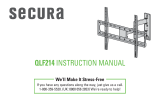
TV tilts for
the perfect
viewing angle
Adjustment knobs allow fi ngertip
control or to restrict movement
Kick stands hold TV from wall to
create room to attach cables
Brackets adjust side to side
within the wall plate for
optimal positioning
Features
Level adjustments create
a worry-free installation
TV brackets designed to fi t TV
hole patterns from 200 x 200 mm
up to 750 x 400 mm

6
NOTE: Not all hardware included will be used.
WARNING: This product contains small items that could be a choking hazard if swallowed.
Before starting assembly, verify all parts are included and undamaged. If any parts are missing or damaged, do not return the damaged item to
your dealer; contact Customer Service. Never use damaged parts!
TV Bracket
TV Bracket
STEP 1 Parts and Hardware
Supplied Parts and Hardware
M4 M6 / M8
Spacer
M8 x 35mm
M6 x 35mm
M6 x 12mm
M6 x 20mm
M4 x 35mm
M4 x 12mm
M8 x 16mm
M8 x 20mm
06
09
04
07
10
11
12
13
x4
x4
x4
x4
x4
x4
x4
x4
08
05
03
x4
x4
x4
01
x1
02
x1
TV Screws
Washers
M4
M6/M8
Spacers

7
5/16 in.
5⁄16 in. x 2 3⁄4 in.
M3
15
16
17
18
x3
x3
x3
x1
STEP 2 Parts and Hardware
Adjustments
Washers
Wall Plate
Lag Bolts
Concrete Anchors
5/16 in.
Allen Key
14
x1

8
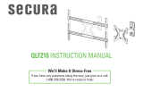
b
M6 M8
FLAT BACK
ROUND BACK CABLESINSET HOLES
M4
1-1 Select TV
Screw Diameter
1-2 Select TV
Screw Length
If your TV has a flat back, use the shorter screws.
Spacers and longer screws are supplied to accommodate:
● irregular / round back TVs
● TVs with inset mounting holes
● extra space needed for cables
Hand thread screws into the threaded inserts
on the back of your TV to determine which
screw diameter (M4, M6, or M8) to use.
STEP 1 Attach Brackets to TV
Too Short
Correct
Too Long
CAUTION:
Verify adequate thread
engagment with the screw or
screw/spacer combination.
- Too short will not hold the TV.
- Too long will damage the TV.
a

9
b
Spacer, long screw and washer
a
Short screw and washer
1-3 Attach TV Brackets
Center the TV brackets
01
and
02
over your TV hole pattern as shown - making sure the brackets are level.
Install using either the short screw and washer or spacer, long screw and washer combination you selected for your TV.
13
02
01
11
11
03
12
12
04
05
08
06
09
07
10

10
CAUTION: Avoid potential personal injuries and property damage!
● Drywall covering the wall must not exceed 16 mm (5/8 in.)
● Minimum wood stud size: common 51 x 102 mm (2 x 4 in.) nominal 38 x 89 mm (1 1/2 x 3 1/2 in.)
● Minimum horizontal space between fasteners: 406 mm (16 in.)
1. Locate studs. Verify the center of the stud(s) using an awl, a thin nail, or an edge to edge stud finder.
NOTE: For assistance in determining wall plate location, see HeightFinder at sanus.com.
2. Level the wall plate
14
and mark the hole locations in the center of the studs.
STEP 2 Attach Wall Plate - Wood Stud Option
1 2
≤16 mm
(5/8 in.)
406-610 mm
(16-24 in.)
14

11
15
17
3 4
3. Remove the wall plate
14
and drill pilot holes.
IMPORTANT: Be sure to drill into the center of the stud.
IMPORTANT: Pilot holes must be drilled to a depth of 75 mm (3 in.), using a 5.5 mm (7/32 in.) diameter drill bit.
4. Install wall plate
14
using lag bolts
15
and washers
17
. Tighten the lag bolts only until the washers are pulled firmly against the wall plate.
CAUTION: Improper use could reduce the holding power of the lag bolt. DO NOT over-tighten the lag bolts.
75 mm
(3 in.)
5.5 mm
(7/32 in.)
14

12
1 2
STEP 2 Attach Wall Plate - Solid Concrete or Concrete Block Option
CAUTION: Avoid potential personal injuries and property damage!
● Mount the wall plate
directly onto the concrete surface
● Minimum solid concrete thickness: 203 mm (8 in.)
● Minimum concrete block size: 203 x 203 x 406 mm (8 x 8 x 16 in.)
● Minimum horizontal space between fasteners: 203 mm (8 in.)
1. Level the wall plate
14
and mark three hole locations.
NOTE: For assistance in determining wall plate location, see HeightFinder at sanus.com.
2. Remove the wall plate
14
and drill pilot holes into concrete. Never drill into the mortar between blocks.
IMPORTANT: Pilot holes must be drilled to a depth of 75 mm (3 in.), using a 10 mm (3/8 in.) diameter drill bit.
10 mm
(3/8 in.)
75 mm
(3 in.)
14

13
3
4
3. Insert concrete anchors
16
.
CAUTION: Be sure the anchors are seated flush with the concrete surface.
4. Install the wall plate
14
using three lag bolts
15
and washers
17
. Tighten all lag bolts only until the washers are pulled firmly against
the wall plate.
CAUTION: Improper use could reduce the holding power of the lag bolt. DO NOT over-tighten the lag bolts.
15
17
14
16

14
HEAVY! You may need assistance with this step.
STEP 3 Hang TV onto Wall Plate
1. Hook the TV brackets
01
and
02
onto the wall plate
14
.
2. Rest the TV into place against the wall.
3. The brackets click and lock the TV in place.
02 01
14
3
21

15
Manage Cables
1. Pull down and hold both release cords while gently pulling the bottom of the TV away from the wall until the kick stands fall into place.
CAUTION: To prevent breaking the locking latch: always pull and hold the release cords down while pulling the TV away from the wall.
2. Temporarily rest the TV on the kick stands while assembling the cables on the TV.
CAUTION: TV is not secured to the wall when it is in the kick stand position. Assistance is recommended for this step.
3. Lift the kick stands up while holding the TV.
4. Gently rest the TV back until the brackets click and lock the TV in place.
Release Cords
Kick Stands
1 2
3
4

16
Your TV should adjust easily when moved, then stay in place.
If your TV is too loose or too tight, adjust the tension knobs
using hex key
18
.
NOTE: Once your TV is in place, tighten the tension
knobs to prevent unwanted movement.
To level your TV, turn the level adjustment screw on the top
of either bracket using hex key
18
to raise or lower that
respective side of the TV.
TV Adjustments
TILT ADJUSTMENT LEVEL ADJUSTMENT
18
18
Loosen
Tighten
Tension Knob
Level Adjustment Screw
Raise
Lower

17
REMOVING THE TV
To remove your TV from the wall plate
14
.
Disconnect all cables and then follow the procedures on PAGE 15
to pull the release cords and pull bottom of TV from wall, then lift
TV off the wall plate to remove.
To reattach, follow the procedures in STEP 3 on PAGE 14.
Slide the TV left or right along the wall plate
14
to reposition.
TV LATERAL SHIFT
14
14

Milestone AV Technologies and its a liated corporations and subsidiaries (collectively, “Milestone”), intend to make this manual accurate and complete. However,
Milestone makes no claim that the information contained herein covers all details, conditions, or variations. Nor does it provide for every possible contingency in
connection with the installation or use of this product. The information contained in this document is subject to change without notice or obligation of any kind.
Milestone makes no representation of warranty, expressed or implied, regarding the information contained herein. Milestone assumes no responsibility for accuracy,
completeness or su ciency of the information contained in this document.
©2013 Milestone AV Technologies, a Duchossois Group Company. All rights reserved. Sanus is a division of Milestone.
All other brand names or marks are used for identifi cation purposes and are trademarks of their respective owners.
Thank you for choosing Sanus! Please take a moment to let us know how we did:
SANUS • 6436 City West Parkway • Eden Prairie, MN 55344 USA
6901-002281 00
Call us: 1-800-359-5520
UK: 0800 056 2853
Email us: [email protected] Leave a review: sanus.com
/