Page is loading ...

VMF
518
INSTRUCTION MANUAL
Scan for easy install video
http://san.us/406
We’ll Make It Stress-Free
If you have any questions along the way, just give us a call.
1-800-359-5520. We’re ready to help!

2
IMPORTANT SAFETY INSTRUCTIONS – SAVE THESE INSTRUCTIONS – PLEASE READ ENTIRE MANUAL PRIOR TO USE
Does your TV weigh more than 75 lb (34 kg) including accessories?
No
—
Perfect!
Yes
—
This mount is NOT compatible. Visit MountFinder.Sanus.com or call 1-800-359-5520 (UK: 0800-056-2853) to fi nd a compatible mount.
Ready to begin?
Please read through these instructions completely to be sure you’re comfortable with this easy install process. Also check your TV
owner’s manual to see if there are any special requirements for mounting your TV.
If you do not understand these instructions or have doubts about the safety of the installation, assembly or use of this product, contact
Customer Service at 1-800-359-5520 (UK: 0800-056-2853).
Do you have all of the tools needed?
Before getting started, let’s make sure this mount is perfect for you!
1
2
3
4
What is your wall made of?
Perfect! Perfect! Call 1-800-359-5520 (UK: 0800-056-2853)
Unsure?
?
Drywall with
wood studs
Solid concrete or
concrete block
5.5 mm
(7/32 in.)
Wood
10 mm
(3/8 in.)
Concrete
75 lb
(34 kg)
1/2 in.
(13 mm)

3
M6x35 mm M8x35 mm
M4x35 mm
M5x35 mm
Spacer
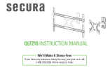
STEP 1 Attach Bracket to TV
Horizontal TV Bracket
Vertical
TV Bracket
04
06
09
x4
x4
x4
03
05
07 08
x4 x4
x4
x4
01
x2
02
x1
NOTE: Not all hardware included will be used.
WARNING: This product contains small items that could be a choking hazard if swallowed.
Before starting assembly, verify all parts are included and undamaged. If any parts are missing or damaged, do not return the damaged
item to your dealer; contact Customer Service. Never use damaged parts!
Parts and Hardware for STEP 1
TV Screws
TV Washers

4
1-1 Select TV Screws
Hand thread screws into the threaded inserts on the back of your TV
to determine which screw diameter (M4, M5, M6, or M8) to use.
1-2 Spacers
Mount the spacers
09
above the TV bracket,
so the TV bracket sits
close to the TV surface
for Flat Back Panels.
CAUTION: Verify adequate thread engagment of the screw/
spacer combination on your TV.
Too short will not hold the TV and too long will damage the TV.
M4
M6
M8
M5
Too Short Correct Too Long
Mount the spacers
09
under the TV bracket to
create extra space needed
for irregular shape TV
backs or large cables.
Spacers and screws are supplied to install your TV bracket.
Determine your preference for spacer configuration when
attaching your TV bracket.
Round Back CablesInset HolesFlat Back
TV Bracket
TV Bracket
09
09
a
b

5
1-3 Attach Horizontal Bracket
1 2
01
01
02
01
01
02
1. Slide the horizontal TV brackets
01
over the ends of the vertical TV bracket
02
.
NOTE: The horizontal and vertical TV brackets must be oriented in the positions shown.
2. Position TV bracket assembly over your TV hole pattern, center horizontally and loosely install
using the spacer, screw and washer combination you selected for your TV.
Pin
a
Spacer, screw and washer
b
Spacer, screw and washer
09
09
03
03
04
04
05
05
06
06
07
07
08
08

6
1-4 Attach Vertical Bracket
3 6
4
5
02
Screws
01
01
01
3. Vertically center the vertical TV bracket
02
.
4. Visually line up the locator hole in the bottom horizontal TV bracket
01
with a hole in the vertical TV bracket
02
.
5. Press and turn a spring screw to secure the vertical TV bracket
02
in place. Push and tighten the remaining three spring screws.
NOTE: You may need to slide the vertical TV bracket
02
up or down while pressing in the spring screw to find the first mounting hole.
6. Tighten the 4 screws (PAGE 5) on the horizontal TV brackets
01
.
01
Spring
Screw
Spring Screw
Locator Hole
TV Bracket
Hole
02
02

7
STEP 2 Attach Arm Assembly/Wall Plate to Wall
Parts and Hardware for STEP 2
For wood stud installations, follow STEP 2A on PAGE 8
For concrete installations, follow STEP 2B on PAGE 12
NOTE: Not all hardware included will be used.
WARNING: This product contains small items that could be a choking hazard if swallowed.
Before starting assembly, verify all parts are included and undamaged. If any parts are missing or damaged, do not return the damaged
item to your dealer; contact Customer Service. Never use damaged parts!
5⁄16 x 3 ½ in.
Sanus Magnetic Stud Finder
13
x2
10
x1
11
x1
12
x1
14
x2
Arm Assembly/Wall Plate
Wall Plate
Template
Lag Bolts
Concrete Anchors

8
1
2
3
CAUTION: Avoid potential personal injuries and property damage!
● Drywall covering the wall must not exceed
16 mm (5/8 in.)
● Minimum wood stud size: common 51 x 102 mm (2 x 4 in.) nominal
38 x 89 mm (1½ x 3½ in.)
● Stud center must be verified
NOTE: See Introducing Sanus Magnetic Stud Finder* located
in your Welcome folder for more detailed operation of stud finder.
1. Locate a nail/screw in the stud using the Sanus magnetic stud finder
12
provided.
2. Find the edges of the stud using the probe
of the stud finder
12
.
3. Mark the center of the stud with pencil.
* WARNING: This product contains a magnet. If an implanted medical device such as a pacemaker or implantable cardioverter defi brillator (ICD)
is in use, magnetic fi elds may a ect the operation of those devices, resulting in serious injury or death. If you have an implanted medical device, keep at
least 13 cm (5 in.) between your device and the magnet. Please consult with your physician or medical professional prior to using this product.
Min. 38 mm
(1 1/2 in.)
12
STEP 2A Wood Stud Option
Min. 89 mm
(3 1/2 in.)
Max. 16 mm
(5/8 in.)

9
4 5 6
89 mm
(3½ in.)
5.5 mm
(7/32 in.)
4. Place the wall plate template
10
at your desired height and position the slotted holes over your stud center line. Level the wall plate
template
10
and tape in place.
NOTE: For assistance in determining wall plate location, see HeightFinder at sanus.com.
IMPORTANT: Be sure you mark and drill into the center of the stud.
5. Drill the two pilot holes using a 5.5 mm (7/32 in.) diameter drill bit.
IMPORTANT: Pilot holes must be drilled to a depth of 89 mm (3 ½ in.).
6. Partially install the top lag bolt
13
,
leaving about 13 mm (1/2 in.) space from the wall.
NOTE: This space allows you to remove the wall plate template
10
and hang the wall plate
11
onto the top lag bolt
13
.
10
10
≈ 13 mm
(
1/2 in.)
10
13

10
7. Remove the wall plate template
10
.
8. Remove the covers on the arm assembly/wall plate
11
.
9. Hang the arm assembly/wall plate
11
on the top lag bolt
13
.
7 8
9
Cover
Cover
11
11
10
13

11
10. Install the bottom lag bolt
13
. Tighten both lag bolts
13
only until they are pulled firmly against the arm assembly/wall plate
11
.
NOTE: Hold the arm assembly/wall plate
11
in place when tightening the first lag bolt
13
to keep the plate from shifting out of place.
CAUTION: Improper use could reduce the holding power of the lag bolts
13
. DO NOT over-tighten the lag bolts.
11. Install the covers on arm assembly/wall plate
11
.
Go to STEP 3 on PAGE 15.
10
Cover
11
Cover
11
13
11

12
1 2
CAUTION: Avoid potential personal injuries and property damage!
● Mount the arm assembly/wall plate
11
directly onto the concrete surface
● Minimum solid concrete thickness: 203 mm (8 in.)
● Minimum concrete block size: 203 x 203 x 406 mm (8 x 8 x 16 in.)
1. Position the wall plate template
10
on the wall at your desired height. Level the wall plate template and mark the hole locations.
NOTE: For assistance in determining wall plate location, see Height Finder at sanus.com.
2. Drill two pilot holes using a 10 mm (3/8 in.) diameter drill bit.
IMPORTANT: Pilot holes must be drilled to a depth of 101 mm (4 in.). Never drill into the mortar between blocks.
3. Remove the wall plate template
10
and insert two anchors
14
.
10 mm
(3/8 in.)
101 mm
(4 in.)
3
STEP 2B Solid Concrete or Concrete Block Option
10
10
14
10

13
CAUTION: Be sure the anchors
14
are seated flush with the concrete surface.
4. Partially install the top lag bolt
13
, leaving about 13 mm (1/2 in.) space from the wall.
NOTE: This space allows you to hang the arm assembly/wall plate
11
onto the top lag bolt
13
.
5. Remove the covers on the arm assembly/wall plate
11
.
6. Hang the arm assembly/wall plate
11
on the top lag bolt
13
.
4
≈13 mm
(
1/2 in.)
5
Cover
Cover
6
13
11
11
13

14
7. Install the bottom lag bolt
13
. Tighten both lag bolts
13
only until they are pulled firmly against the arm assembly/wall plate
11
.
NOTE: Hold the arm assembly/wall plate
11
in place when tightening the first lag bolt
13
to keep the wall plate from shifting out of place.
CAUTION: Improper use could reduce the holding power of the lag bolt
13
. DO NOT over-tighten the lag bolts.
8. Install the covers on arm assembly/wall plate
11
.
87
Cover
Cover
11
11
13

15
HEAVY! You may need assistance with this step.
STEP 3 Hang TV onto Arm Assembly/Wall Plate
1. Position the arm assembly/wall plate
11
so the elbow is pressed against the wall.
2. Pull out the safety release pin on vertical TV bracket
02
and turn counterclockwise until the pin locks in place.
1 2
11
02
Safety
Release
Pin

16
3. Hang the TV onto the arm assembly/wall plate
11
by hooking the top support.
4. Press the bottom of the TV into the arm assembly/wall plate
11
until the safety catch locks the TV in place.
5. Turn the safety release pin clockwise until the pin springs back into place and locks the release cord.
CAUTION: Avoid potential personal injury or property damage! Always make sure the safety release pin is fully seated and the release
cord is locked, so the TV is securely fastened to the arm assembly/wall plate
11
53
4
Top
Support
Safety
Catch
Safety
Release
Pin
11

17
Route your TV cables along the arm assembly/wall plate
11
and press into the channels in the arm as shown.
Manage Cables
Cables
11

18
Adjustments
TILTLEVEL
Your TV should adjust easily when
moved, then stay in place.
Adjust the tension screw if your TV is
too loose or too tight.
NOTE: Once your TV is in place, you
can tighten the tension screw to prevent
unwanted movement.
Your TV should adjust easily when moved, then
stay in place.
Adjust the tension screw if your TV naturally tilts
up or down.
NOTE: If you do not intend to adjust the tilt for
different viewing locations, you can , tighten the
tension screw to prevent unwanted movement.
Tension
Screw
Tighten
Loosen

19
REMOVING THE TV
1. Disconnect all cables from the TV.
2. Pull out the safety release pin on vertical TV bracket
02
and turn counterclockwise until the pin locks in place.
3. Pull and hold the release cord while pulling the bottom of the TV outward.
4. Lift the TV off the arm assembly/wall plate
11
to remove.
NOTE: To hang the TV back on the arm assembly/wall plate
11
, follow Step 3 on PAGES 15 and 16.
HEAVY! You may need assistance with this step.
Release Cord
Safety
Release Pin
11
02
1
2
3
4

20
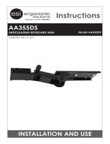
Features
Fully articulating arm
creates 3-point movement
for optimal viewing position
Adjustment allows fi ngertip control
of TV or restriction of TV movement
TV tilts up
or down for
the perfect
viewing angle
Locking mechanisms for added security
Cable
channels hold
cables along
mount arm for
a clean look
Bracket rotates 90
degrees to the left or
right for landscape or
portrait viewing
TV bracket expands
to fi t TV hole patterns
from 200 x 200 mm up
to 400 x 400 mm
Fully articulating arm extends from
82 mm (3.2 in) to 474 mm (18.7 in.)
/