RDLED2TL ND2TL WITH TRIMLESS INSTRUCTIONS
Thank you for buying RAB lighting xtures. Our goal is to design the best quality products to get the job done right. We’d like to hear your comments.
Call the Marketing Department at 888-RAB-1000 or email: marketing@rablighting.com
Fig: 3
TROUBLESHOOTING
1. Check that the line voltage at the xture is correct. Refer
to wiring directions.
2. Is the xture grounded properly?
CLEANING & MAINTENANCE
CAUTION: Be sure xture temperature is cool enough to
touch. Do not clean or maintain while xture is energized.
1. Do not open xture to clean the LED. Do not touch
the LED.
2. Do not touch reector, lens or trim cone.
3. Do not clean any xture surface with wood base cleaning
material such as paper towels or tissues.
WIRING
RISK OF FIRE. Compatible with TRIAC dimmers at 120V, 50
or 60Hz. Drop down supply wires must be at least 9” long to
allow xture removal. For non-dimming (on/o), Electronic
Low Voltage (ELV) and TRIAC dimming, follow the wiring
directions in Fig. 6.
1. Connect GROUND wire from xture to supply ground.
2. Connect black xture lead to the (+) LINE supply lead.
3. Connect white xture lead to the (-) COMMON supply lead.
SPACKLED FLANGE MOUNTING
1. Place Spackle Flange on ceiling and align the opening
with the ceiling cutout. Carefully mark the (4) hole
pattern on ceiling and remove Spackle Flange.
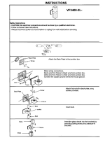
2. For New Construction (Fig: 3): Use a 7/32” drill bit to drill
ceiling typical 5/8” ceiling depth. Align rib of Spackle
Flange to rib in Rough-in. Insert the Spackle Flange and
secure with 8-32 x 1-1/2” at head counter shank machine
screws.
NOTE: DO NOT DRILL HOLES DEEPER THAN THE
CEILING THICKNESS.
3. For Remodeler Unit without rough-in frame (Fig4): Use
5/16” drill bit and drill ceiling at 4 marked places. Install
Wall Anchors and secure Spackled Flange with 8-32 X
1-1/4” at head counter shank sheet metal screws.
4. Apply joint compound to spackle frame edge. Remove
Dust protector and remove small debries and make it
ush to ceiling.
8/32 X 1-1/4”
screws at head
counter shank(4)
Wall Anchors (4)
Fig: 4
WALLWASH MOUNTING
1. For the Wallwash Model, orient the xture such that
the Reector is aimed in correct orientation. Look for
‘Towards the Wall’ label on the xture.
2. If necessary, the position of the wall wash reector can be
changed. Unscrew the two Trim Ring screws and remove
the Trim Ring.
3. Remove the Friction Ring, and change the position
of the reector. Note: Square Wall Wash reector can
rotate by 90. Be sure the slot on the Reector is aligned
to slot in Trim Ring.
Spackled Flange
Ceiling
Spackled Flange
Ceiling
8-32 x 1-1/2” screws
at head counter
shank (4)
Note: These instructions do not cover all details or variations in
equipment nor do they provide for every possible situation during
installation, operation or maintenance.
Fig: 6
Trim Ring Screws
Square Wall Wash reector
Trim Ring
Friction Ring
Fig: 5