Page is loading ...

Submit comments about this document at: [email protected]
Sun Microsystems, Inc.
www.sun.com
Virtual Tape Library
VTL Value Hardware Installation Guide
Part No. 316196101
Aug 2007, Revision A
EC000066

SunMicrosystems,Inc.hasintellectualpropertyrightsrelatingtotechnologythatisdescribedinthisdocument.Inparticular,andwithout
limitation,theseintellectualpropertyrightsmayincludeoneormoreoftheU.S.pa tentslistedathttp://www.sun.com/patentsandoneormore
additionalpatentsorpendingpatentapplicationsintheU.S.and
inothercountries.
Thisdocumentandtheproducttowhichitpertainsaredistributedunderlicensesrestrictingtheiruse,copying,distribution,and
decompilation.Nopartoftheproductorofthisdocumentmaybereproducedinanyformbyanymeanswithoutpriorwrittenauthorizationof
Sunanditslicensors,if
any.
Third‐partysoftware,includingfonttechnology,iscopyrightedandlicensedfromSunsuppliers.
PartsoftheproductmaybederivedfromBerkeleyBSDsystems,licensedfromtheUniversityofCalifornia.UNIXisa registeredtrademarkin
theU.S.andinothercountries,exclusivelylicensedthroughX/OpenCompany,Ltd.
Sun,SunMicrosystems,theSunlogo,Java,AnswerBook2,docs.sun.com,andSolarisaretrademarksorregisteredtrademarksofSun
Microsystems,Inc.intheU.S.andinothercountries.
AMDOpteronisatrademarkorregisteredtrademarkofAdvancedMicrodevices,Inc.
AllSPARCtrademarksareusedunderlicenseandaretrademarksorregisteredtrademarksofSPARC
International,Inc.intheU.S.andinother
countries.ProductsbearingSPARCtrademarksarebaseduponanarchitecturedevelopedbySunMicrosystems,Inc.
TheOPENLOOKandSun™GraphicalUserInterfacewasdevelopedbySunMicrosystems,Inc.foritsusersandlicensees.Sunacknowledges
thepioneeringeffortsofXeroxinresearching
anddevelopingtheconceptofvisualorgraphicaluserinterfacesforthecomputerindustry.Sun
holdsanon‐exclusivelicensefromXeroxtotheXeroxGraphicalUserInterface,whichlicensealsocoversSun’slicenseeswhoimplementOPEN
LOOKGUIsandotherwisecomplywithSun’swrittenlicenseagreements.
U.S.GovernmentRights—Commercialuse.
GovernmentusersaresubjecttotheSunMicrosystems,Inc.standardlicenseagreementand
applicableprovisionsoftheFARanditssupplements.
DOCUMENTATIONISPROVIDEDʺASISʺANDALLEXPRESSORIMPLIEDCONDITIONS,REPRESENTATIONSANDWARRANTIES,
INCLUDINGANYIMPLIEDWARRANTYOFMERCHANTABILITY,FITNESSFORAPARTICULARPURPOSEORNON‐INFRINGEMENT,
AREDISCLAIMED,EXCEPTTOTHEEXTENTTHATSUCHDISCLAIMERSAREHELDTOBELEGALLYINVALID.
Copyright2007SunMicrosystems,Inc.,4150NetworkCircle,SantaClara,Californie95054,Etats‐Unis.Tousdroitsréservés.
SunMicrosystems,Inc.alesdroitsdepropriétéintellectuelsrelatantsàlatechnologiequiestdécritdanscedocument.En
particulier,etsansla
limitation,cesdroitsdepropriétéintellectuelspeuventinclureunouplusdesbrevetsaméricainsénumérésàhttp://www.sun.com/patentsetun
oulesbrevetsplussupplémentairesoulesapplicationsdebrevetenattentedanslesEtats‐Unisetdanslesautrespays.
Ceproduitoudocumentestprotégépar
uncopyrightetdistribuéavecdeslicencesquienrestreignentl’utilisation,lacopie,ladistribution,etla
décompilation.Aucunepartiedeceproduitoudocumentnepeutêtrereproduitesousaucuneforme,parquelquemoyenquecesoit,sans
l’autorisationpréalableetécritedeSunetdesesbailleursdelicence,s’ilyena.
Lelogicieldétenupardestiers,etquicomprendlatechnologierelativeauxpolicesdecaractères,estprotégéparuncopyrightetlicenciépardes
fournisseursdeSun.
DespartiesdeceproduitpourrontêtredérivéesdessystèmesBerkeleyBSDlicenciésparl’UniversitédeCalifornie.UNIXest
unemarque
déposéeauxEtats‐Unisetdansd’autrespaysetlicenciéeexclusivementparX/OpenCompany,Ltd.
Sun,SunMicrosystems,lelogoSun,Java,AnswerBook2,docs.sun.com,etSolarissontdesmarquesdefabriqueoudesmarquesdéposéesde
SunMicrosystems,Inc.auxEtats‐Unisetdansd’autrespays.
AMDOpteronest
unemarquedefabriqueouunemarquedeposeedeAdvancedMicrodevices,Inc.
TouteslesmarquesSPARCsontutiliséessouslicenceetsontdesmarquesdefabriqueoudesmarquesdéposéesdeSPARCInternational,Inc.
auxEtats‐Unisetdansd’autrespays.LesproduitsportantlesmarquesSPARCsontbaséssurune
architecturedéveloppéeparSun
Microsystems,Inc.
L’interfaced’utilisationgraphiqueOPENLOOKetSun™aétédéveloppéeparSunMicrosystems,Inc.poursesutilisateursetlicenciés.Sun
reconnaîtleseffortsdepionniersdeXeroxpourlarechercheetledéveloppementduconceptdesinterfacesd’utilisationvisuelleougraphique
pourl’industriedel’informatique.SundétientunelicensenonexclusivedeXeroxsurl’interfaced’utilisationgraphiqueXerox,cettelicence
couvrantégalementleslicenciéesdeSunquimettentenplacel’interfaced’utilisationgraphiqueOPENLOOKetquienoutreseconformentaux
licencesécritesdeSun.
LADOCUMENTATIONESTFOURNIEʺENL’ÉTATʺETTOUTESAUTRES
CONDITIONS,DECLARATIONSETGARANTIESEXPRESSES
OUTACITESSONTFORMELLEMENTEXCLUES,DANSLAMESUREAUTORISEEPARLALOIAPPLICABLE,YCOMPRISNOTAMMENT
TOUTEGARANTIEIMPLICITERELATIVEALAQUALITEMARCHANDE,AL’APTITUDEAUNEUTILISATIONPARTICULIEREOUA
L’ABSENCEDECONTREFAÇON.
SunMicrosystems,Inc.,4150NetworkCircle,SantaClara,California95054,U.S.A.
Allrightsreserved.Copyright2007

Revision History iii
RevisionHistory
Short Name Part Number Dash Date Comments
VTL Value Hardware Installation Guide 316196101 A August 2007

iv VTL Value Hardware Installation Guide • Aug 2007

v
Contents
About this book ix
Using this book ix
Taking advantage of this book’s hypertext features x
Understanding the conventions used in this book x
Using the Sun StorageTek Customer Resource Center (CRC) to obtain the latest
information and supporting resources xi
Commenting on this book xi
1. Installing VTLVal u e hardware 1
InstallingtheVTLValueapplianceinanequipmentrack 1
Preparingforthejob 1
▼ Obtaining required tools, personnel, and materials 2
Installingslide‐railasse mblies 3
▼ Preparing the slide-rail assemblies for installation 3
▼ Attaching the inner rails to the server chassis 4
▼ Positioning the outer/middle rail assembly in the rack 5
▼ Attaching the outer/middle rail assembly to the rack 8
▼ Adjusting and securing middle/outer slide rails 11
Mountingtheapplianceintherack 13
Cabling 16

vi VTL Value Hardware Installation Guide • Aug 2007
Installingthecablemanagementarm 16
▼ Attaching the Outer Rail Extension 17
Routingandconnectingcables 20
▼ Installing data and power cables 20
StartingtheVTLappliance 22
▼ Powering up 22
▼ Powering down 24
2. SettinguptheVTLVal u eILOMserviceprocessor 25
UnderstandingtheILOM 25
ChangingtheIPaddressoftheILOM SP 26
▼ Attaching a laptop to the ILOM via the VTL private network 26
▼ Changing the IP address of the ILOM 28
ChangingtheILOMpassword 29
▼ Resetting the default ILOM password 29
Checkingthehealthoftheinternalstoragesystems 30
▼ Accessing the Solaris desk top via the ILOM 31
▼ Running basic storage diagnostics 33
ChangingtheSolarisrootpassw ord 35
▼ Changing the default Solaris root password 36
Loggingou t 36
▼ Logging out of the operating system and ILOM 36
A. The backandfrontpanelsoftheVTLValue server 39
B. VTLprivatenetwork addresses 41
C. ConnectingtoILOMviaaserialport 43
D. ILOMcommandreference 45


viii VTL Value Hardware Installation Guide • Aug 2007

ix
About this book
This book describes the installation and initial configuration processes specific to the Sun
StorageTek VTL Value appliance. In VTL Value deployments, it supersedes the Sun Fire™
X4500 Server Installation Guide (819-4358-11) that ships with the X4500 platform. While
the VTL Value appliance hardware is almost identical to the X4500, it has been specially
preconfigured to host Virtual Tape Library software on the Solaris operating system.
Using this book
This book leads you through the process of setting up the VTL Value equipment from
beginning to end, with all the needed information immediately to hand and the alternatives
clearly indicated. Each chapter and section begins with a list of the tasks it contains. Tasks
are presented in order, and the steps in each process are numbered, in the sequence in which
they are to be performed. Conditional steps (steps that you perform only in specified
circumstances) begin with the condition (“If A ...”) and end with the corresponding action
(“... do B”); if the condition does not apply, you simply skip the step. Each task ends with a
reference to the next task in the sequence:
Next task: “Installing slide-rail assemblies” on page 3.
When the setup process branches, the tasks ends with conditional alternatives:
Next task:
• If the customer does not plan to run the management console from a host on the
local area network (LAN), press Skip, and go to the next task.
• Otherwise, carry out the procedure “Configuring the Ethernet management
interface” on page 57.
To minimize the time you spend switching between publications or major sections of the
document, we have made an effort to avoid cross references to external information wherever
possible. If you need to have a figure, a table, or a procedure, it should always be, at worst,
on a neighboring page.

x VTL Value Hardware Installation Guide • Aug 2007
The chapters are organized to reflect top-level tasks. The first chapter details the physical
installation of the appliance hardware, including rack mounting, cabling, and power up
procedures. The second chapter explains the initial configuration of the operating system
software and network and some basic checks that should be run on a newly installed system.
Appendices provide additional information that, while not essential to a normal installation,
may prove useful in special circumstances. These list the private network addresses used
when installing the VTL Value appliance, provide instructions for serially connecting to the
VTL Value Integrated Lights Out Manager (ILOM) service processor, and summarize
commands that can be entered at the ILOM commandline interface (CLI).
Taking advantage of this book’s hypertext features
If you choose to view this book online, rather than in printed form, you can jump quickly to
any part of the book by clicking on the corresponding entry under the Bookmarks tab on
the left side of the Adobe Acrobat interface. In addition, clicking on entries in the table of
contents, cross references, or references to subsequent tasks will take you directly to the
indicated part of the document. You can then use the back arrow on the Adobe Acrobat
Reader to return, if desired, to the point you left. In addition, clicking on most Uniform
Resource Locators (URLs) and on most references to online resources will open your default
web browser to the corresponding web page, so that you can, if necessary, obtain a required
download immediately (be aware, however, the URL to specific pages change frequently and
may not always be accurate).
Understanding the conventions used in this book
The table below illustrates the conventions that represent literal and variable values,
commands, and property names in this book.
Convention Meaning Examples
AaBbCc123 Fixed-width text is used for literal values, including
names of commands, files, directories, literal computer
inputs/outputs, and Uniform Resource Locators (URLs)
Edit your.login file.
Use ls -a to list files.
% You have mail.
AaBbCc123 Oblique text is used for variables that stand for real names
or values and for book titles.
To delete a file, type:
rm filename.
ABCD
Bold, san-serif text indicates callouts in illustrations. Click Submit
(
A below).
1. Numbered paragraphs indicate steps in a process that
should be executed in sequential order.
■ Bulleted paragraphs indicate lists of alternatives or
components.

About this book xi
Using the Sun StorageTek Customer Resource Center (CRC) to
obtain the latest information and supporting resources
The Sun StorageTek Customer Resource Center <www.support.storagetek.com>
stores the latest documentation, software updates, and licensing resources for VTL Value
solutions. Always check the CRC for updates to this document before proceeding.
Documents distributed on CDROM may not reflect the latest changes to VTL hardware,
software, and services.
You must have an account to use the CRC. If you do not currently have access, click the
Request a CRC Password link at the URL shown above.
Commenting on this book
Sun welcomes your comments and suggestions for improving this book. Contact us at
[email protected]. Please include the title, part number, issue date, and revision: VTL
Value Hardware Installation Guide , part number 316196101 (Aug 2007 revision A).

xii VTL Value Hardware Installation Guide • Aug 2007

316196101 • A 1
CHAPTER
1
Installing VTL Value hardware
This chapter describes the process of physically installing the VTL Value appliance and
applying power. The tasks break down as follows:
This chapter contains procedures for:
■ “Installing the VTL Value appliance in an equipment rack” on page 1 (if a rack is used)
■ “Cabling” on page 16
■ “Starting the VTL appliance” on page 22.
Installing the VTL Value appliance in an
equipment rack
To safely install the VTL Value appliance in an equipment rack, you need to carry out the
following tasks:
■ “Preparing for the job” on page 1
■ “Installing slide-rail assemblies” on page 3
■ “Mounting the appliance in the rack” on page 13
Preparing for the job
Before you start the assembly and installation process, you must assess the compatibility of
the selected rack and gather the necessary personnel, tools, and materials. Proceed as
follows.

INSTALLING THE VTL VALUE APPLIANCE IN AN EQUIPMENT RACK
2 VTL Value Hardware Installation Guide • Aug 2007 A • 316196101
▼ Obtaining required tools, personnel, and materials
1. Make sure that the selected rack meets the following specifications:
■ The rack has four posts, with a mounting at both front and rear (two-post racks are not
compatible with the VTL Value slide-rails).
■ The horizontal opening and unit vertical pitch of the rack conform to ANSI/EIA
310-D-1992 or IEC 60927 standards.
■ The rack’s front and rear rack-mounting planes are 23-34 inches (58-87 cm) apart.
■ The minimum depth from the rack’s front cabinet door to the front rack-mounting plane is
1.85 inches (4.7 cm).
■ The minimum depth from the rear cabinet door to the front rack-mounting plane is
38 inches (96.5 cm) with the cable-management arm installed (recommended) or
31.5 inches (80.0 cm) without the cable management arm.
■ The minimum width between obstructions (such as structural supports and cable troughs)
is 18 inches (45.6 mm) at all points between the front and rear mounting planes.
2. Make sure that the available power meets the requirements listed in the table below:
3. Have the orderable slide-rail assemblies at hand.
4. Have the following tools at hand:
■ one 10-inch #2 Phillips screwdriver, preferably with a magnetic tip
■ a carpenter’s spirit level
■ a mechanical lift (highly recommended).
Caution – The VTL Value appliance weighs 160 pounds (72.7 kg) when fully loaded with
components. To prevent injury to personnel or damage to the equipment, Sun strongly
recommends using a mechanical lift when installing the server in a rack.
5. If a mechanical lift is not available, make sure that at least four trained people are
available to remove the server or reduce the weight of the server by removing
components:
■ Remove both power supplies.
■ Remove the system controller.
Location Voltage Amperage Plug type Receptacle type
US/North America: 250 VAC 30 A NEMA L6 30P NEMA L6-30R
EMEA: 230 VAC 32 A IEC-309P IEC-309R

INSTALLING THE VTL VALUE APPLIANCE IN AN EQUIPMENT RACK
316196101 • A Chapter 1 Installing VTL Value hardware 3
■ Label the hard disk drives in slots 2 to 46 and then remove them (you will reinstall the
drives in their original slots using the labels as a guide).
Do not uninstall the fan trays or the bootable drives in slots 0 and 1.
6. If a mechanical lift is available, make sure that at least three people are on hand to
install the server in the rack.
It takes two people to operate the lift and install the server and one additional person to
insure that the rails are engaged correctly.
Next task: “Installingslide‐railassemblies”onpage 3.
Installing slide-rail assemblies
The VTL Value slide-rail system use three-part rails. Each rail assembly consists of an outer
rail that is fixed to the equipment rack, an inner rail that is fixed to the chassis of the VTL
Value appliance, and a middle rail that slides on the inner and outer rails. To install the rail
assemblies, carry out the following tasks:
■ “Preparing the slide-rail assemblies for installation” on page 3
■ “Attaching the inner rails to the server chassis” on page 4
■ “Positioning the outer/middle rail assembly in the rack” on page 5.
■ “Attaching the outer/middle rail assembly to the rack” on page 8.
■ “Adjusting and securing middle/outer slide rails” on page 11.
▼ Preparing the slide-rail assemblies for installation
The slide-rail assemblies are shipped assembled, so you have to take them apart before you
proceed further. Prepare each rail assembly as described below.
1. Unpack the slide-rail assembly.
2. Place the assembly on a flat surface.

INSTALLING THE VTL VALUE APPLIANCE IN AN EQUIPMENT RACK
4 VTL Value Hardware Installation Guide • Aug 2007 A • 316196101
3. Push the slide-rail lock (A below) to release the inner rail, and start to pull the inner
rail out of the middle rail (
B).
4. Continue to pull the inner rail out of the middle rail (
C above) until it contacts the
internal stop (
D).
5. Press the Push Here button on the green mounting-bracket release (
E above), and pull
the mounting bracket free of the middle/outer rail assembly.
6. Repeat for the remaining slide-rail assembly.
Next task: “Attachingtheinnerrailsto these rverchassis”onpage 4.
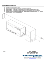
▼ Attaching the inner rails to the server chassis
This procedure explains how to attach the inner rails to the server chassis. For each rail,
proceed as described below.
C
A
E
B
D

INSTALLING THE VTL VALUE APPLIANCE IN AN EQUIPMENT RACK
316196101 • A Chapter 1 Installing VTL Value hardware 5
1. Position the inner rail (A below) against the chassis with the slide-rail lock (B) at the
front.
2. Align the three pairs of keyed openings on the inner rail with the three pairs of locating
pins on the side of the chassis (
C above).
3. While pressing the rear of the rail against the side of the chassis, push the rail toward
the rear of the chassis (
D above) until the rail clip (E) locks into place with an audible
click.
4. Make sure that all six locating pins are locked into the keyed openings.
Next task: Oncebothinnerrailshavebeenattached,go to“Positioningtheouter/middle
railassemblyinthe rack”on page 5.
▼ Positioning the outer/middle rail assembly in the rack
The VTL Value appliance is four rack-units (4U) high and quite heavy, due to the number of
internal storage disks installed. You must therefore position the appliance in the rack
carefully. The chosen location must allow enough space for a 4U appliance while presenting
the smallest possible tipping hazard. Proceed as follows.
B
D
E
A
C
C
C

INSTALLING THE VTL VALUE APPLIANCE IN AN EQUIPMENT RACK
6 VTL Value Hardware Installation Guide • Aug 2007 A • 316196101
1. Before you start, select the lowest possible position in the rack, and deploy the rack’s
anti-tilt bar.
A top-heavy system tips over easily. So always load equipment into a rack from the bottom
up and always place the heaviest equipment as low as possible. Always use the anti-tilt bar
to keep the rack from tipping during installation. See the service label on the VTL Value
appliance cover and/or the label on the rack.
2. Place the paper, rack-mount template (
E below) in the selected position.
The rack-mount template ships with the slide-rail assemblies. It is the same height as the
appliance (four rack-units—4U) and is marked with four arrows that show the location of the
rail mounting screws. In a rack with 3 mounting holes per rack unit (as in the illustration),
the template covers 12 holes.
3. Use the arrows on the template to select the rack mounting hole that will take the top
slide-rail mounting screw (
F above).
In the illustration above, the installed position of the slide rail is shown in pale gray.
E
F
4 U
4 U

INSTALLING THE VTL VALUE APPLIANCE IN AN EQUIPMENT RACK
316196101 • A Chapter 1 Installing VTL Value hardware 7
4. At the rear of the rack, use tape (G below) or a pin to temporarily mark the mounting
hole (
H) that corresponds to the mounting hole that you selected on the front.
5. Repeat steps 2-4 for the remaining middle/outer rail.
Next task: “Attachingtheouter/middle railassemblytotherack”on page 8.
G
H
4 U

INSTALLING THE VTL VALUE APPLIANCE IN AN EQUIPMENT RACK
8 VTL Value Hardware Installation Guide • Aug 2007 A • 316196101
▼ Attaching the outer/middle rail assembly to the rack
1. Before you begin, push the middle rail into the corresponding outer rail so that the ends
are more or less flush. To do this, release the spring-activated slide-rail lock (
A below)
by pushing twice in the direction shown (
B), then telescope the middle rail into the outer
rail (
C):
2. Adjust the length of the middle/outer slide-rail assemblies to the distance between the
front and rear posts of the rack (
D above).
A
B
C
D
/