Page is loading ...

Kit includes
(1) CE-99001B .................................................36” Antirock® Bar
(1) CE-9900JLFL .............................................Frame Mounting Bracket (L)
(1) CE-9900JLFR .............................................Frame Mounting Bracket (R)
(2) CE-99003-JKL ...........................................Antirock® Steel Arm
(2) CE-9901D...................................................Antirock® Bushing
(4) CE-98093A624 .........................................M10 x 1.5mm x 30mm Bolt
(2) CE-92620A607 .........................................5/16”-24 x ¾” Bolt
(2) CE-91090A111 .........................................5/16” Washer
(2) CE-91102A755 .........................................5/16” Lock Washer
(2) CE-91257A661 .........................................3/8”-24 X 2 ½” Bolt
(2) CE-95615A150 .........................................3/8”-24 Nylock Nut
(2) CE-9901RD4 .............................................8 1/2” End Link Rod
(1) CE-99006 ...................................................End Link Studded Heim (RH)
(1) CE-99006B .................................................End Link Thru-Bolt Heim (RH)
(2) CE-99006L .................................................End Link Studded Heim (LH)
(4) CE-95615A220 .........................................½”-20 Nylock Nut
(2) CE-95462A525 .........................................½”-20 Jam Nut (RH Thread)
(2) CE-H0020 ...................................................½”-20 Jam Nut (LH Thread)
(1) CE-91257A751 .........................................½”-20 x 3” Grade 8 Bolt
(2) CE-H0014 ...................................................½” Flat Washer
(2) CE-9900JLFS .............................................Heim Spacer
(2) CE-9900S ...................................................ANTIROCK® Sticker
Required Tools
- 15mm wrenches & sockets
- 18mm wrenches & sockets
Instructions
** Note: use blue loctite on all hardware that you install. **
1) Remove the factory front anti-sway bar and links using a 15mm socket at the frame and and 18mm socket and wrench at the housing tab.
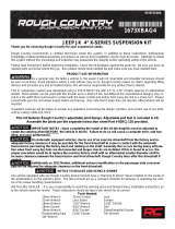
2) Knock the white Antirock® bushings into the frame brackets from the sides of the brackets that have the protruding hubs. (Fig. 1)
3) Using the supplied 10mm bolts, some blue loctite and a 14mm socket, install the frame brackets to the bottoms of the frame rails, protruding
hub side facing out. Tighten and torque brackets to 40 ft. lbs. now. NOTE: all frames have variances! In our instance, the leading edge of the
driver’s side bracket contacted a frame bracket weld and we had to grind the weld down a touch for clearance. (Fig. 2)
4) Grease the insides of the white bushings and both ends of the sway bar and then install the bar thru the 2 bushings. Center the bar in the bushings.
This step will most likely require the use of a mallet. (Fig. 3)
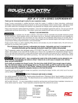
5) Install the 2 black Antirock® arms onto the sway bar splines. Make sure to clock the arms the same from side to side. Use the 5/16” bolts, lock
washers & fender washers into the threaded holes at the ends of the bar to retain the arms to the bar. Next, install the 3/8” bolts and nyloc nuts
into the ends of the arms and tighten with a 9/16” wrench & socket. (Fig. 4)
6) Assemble the end links by putting the jam nuts onto the 8 1/2” rods rst, and then thread the heim joints on. Set to XX” from center to center. (Fig. 5)
7) Install and tighten the link with the studded heims on both ends onto the driver’s side of the vehicle using 5/8” & 3/4” wrenches.
Fits
- All models of 2018 & up Jeep JL Wrangler
- Mallet
- Blue loctite
- 1/2” wrench
- 9/16” wrenches & sockets
- Tape Measure
- 11mm or Crescent wrench
- 14mm sockets
- 5/8” wrench
- 3/4” wrenches & sockets

8) Install and tighten the link with the thru-bolt heim onto the passenger’s side using 5/8” & 3/4” wrenches at the top and a 3/4 socket and wrench
at the housing side. NOTE: install the heim joint spacers, small side toward the heim, on both sides of the lower heim when installing!
9) Double check your center to center on the end links, adjust as necessary and then lock down the link jam nuts with an 11mm or Crescent & a
3/4” wrench.
10) If you removed your wheels and tires for this installation process, reinstall them now and torque to the factory specs. Congratulations, you’re done!
Fig. 1 Fig. 2
Fig. 3 Fig. 4
Fig. 5

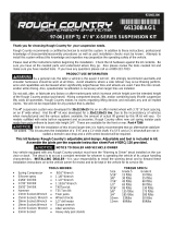
Fig. 6 Fig. 7
Completed installation.
Torque Specs.
M10..............................40 ft. lbs.
5/16”-24.....................20 ft. lbs.
3/8”-24........................35 ft. lbs.
1/2”-20........................85 ft. lbs.
Lug Nuts.....................110 ft. lbs.

Proper Antirock® Adjustment
To correctly adjust a front or rear Antirock sway bar’s end links, the frame of the vehicle must be raised so that the axle assembly drops out
of the vehicle unitl it reaches the middle of the available suspension travel of the vehicle. This is di erent on every vehicle. Rule of thumb is that
the black Antirock arms should be level when the axle assembly is in the middle of it’s travel.
Secondly, be advised! At full suspension droop, the arm should never drop down far enough to get anywhere close to forming a straight line with
the end link rod. If this situation is occuring, or is something that you can forsee happening on your vehicle, you are at risk of the arm going
past center and ipping upside-down toward the bumper of the vehicle. When/if this occurs, the arms, and/or the link rods may be destroyed. This
situation can be prevented by installing longer vertical link rods that are of more suitable length for your application. Longer link rods are available
for purchase separately. Currie will not warranty any arms or link rods that are damaged due to this situation.
Available Link Rods: feature 2 1/2” of RH & LH threads (with the exception of the 14” rods that feature 4” of RH threads) allowing them to
be cut down if necessary for an exact t in your application.
CE-9901RD3 6.5” long Antirock sway bar link rod
CE-9901RD4 8.5” long Antirock sway bar link rod
CE-9901RD5 10.5” long Antirock sway bar link rod
CE-9901RD2 14” long Antirock sway bar link rod
/