Page is loading ...

Thermo Fisher Scientific
Environmental Instruments
Water Analysis Instruments
166 Cummings Center
Beverly, MA 01915 USA
Tel: 978-232-6000
Toll Free: 800-225-1480
Dom. Fax: 978-232-6015
Int’l. Fax: 978-232-6031
www.thermo.com/water
User Guide
ROSS® Process
Combination pH
Electrode

ROSS and the COIL trade dress are trademarks of Thermo Fisher Scientific Inc.
AQUAfast, Cahn, ionplus, KNIpHE, No Cal, ORION, perpHect, PerpHecT, PerpHecTion,
pHISA, pHuture, Pure Water, Sage, Sensing the Future, SensorLink, ROSS, ROSS
Ultra, Sure-Flow, Titrator PLUS and TURBO2 are registered trademarks of
Thermo Fisher.
1-888-pHAX-ION, A+, All in One, Aplus, AQUAsnap, AssuredAccuracy, AUTO-BAR,
AUTO-CAL, AUTO DISPENSER, Auto-ID, AUTO-LOG, AUTO-READ, AUTO-STIR, Auto-Test,
BOD AutoEZ, Cable-Free, CERTI-CAL, CISA, DataCOLLECT, DataPLUS, digital LogR,
DirectCal, DuraProbe, Environmental Product Authority, Extra Easy/Extra Value,
FAST QC, GAP, GLPcal, GLPcheck, GLPdoc, ISEasy, KAP, LabConnect, LogR, Low
Maintenance Triode, Minimum Stir Requirement, MSR, NISS, One-Touch, One-Touch
Calibration, One-Touch Measurement, Optimum Results, Orion Star, Pentrode,
pHuture MMS, pHuture Pentrode, pHuture Quatrode, pHuture Triode, Quatrode,
QuiKcheK, rf link, ROSS Resolution, SAOB, SMART AVERAGING, Smart CheK, SMART
STABILITY, Stacked, Star Navigator 21, Stat Face, The Enhanced Lab, ThermaSense,
Triode, TRIUMpH, Unbreakable pH, Universal Access are trademarks of
Thermo Fisher.
© 2008 Thermo Fisher Scientific Inc. All rights reserved. All trademarks are the
property of Thermo Fisher Scientific Inc. and its subsidiaries.
The specifications, descriptions, drawings, ordering information and part numbers
within this document are subject to change without notice.
This publication supersedes all previous publications on this subject.

1ROSS® Process pH Electrode User Guide
Introduction
General Information
The ROSS process pH electrode, Cat. No. 2001SC, is a
combination electrode designed for online applications. The pH
sensing electrode and reference electrode are combined into a
single electrode. This electrode is designed to be used in the
Orion flow cell, Cat. No. 2001FC. This flow cell is designed to
hold and position the electrode for optimal results.
The 2001SC ROSS combination pH electrode is a research-
grade electrode designed specifically for use in online pH
measurement applications. It is designed with a sidearm, which
allows it to be attached to a reservoir of specially formulated
ROSS reference filling solution. This ensures that the outer
reference chamber is always full, allowing the ceramic liquid
junction to flow freely.
Figure 1 – ROSS Process Combination pH Electrode
Side
Arm
Screw
Cap
Reference
Coil
Sensing
Element
Reference
Junction
FIG 1

2ROSS® Process pH Electrode User Guide
Theory of Operation
With its unique internal element system, the 2001SC ROSS
process combination pH electrode provides far better stability,
faster response and greater accuracy than can be obtained
from any conventional electrode with silver chloride or calomel
internal systems. The electrode response is fast; even in
samples varying by 50 °C or more in temperature. Drift is
less than 0.02 pH units per day, which eliminates the need for
frequent standardization.
The ROSS internal system is designed to have virtually zero
temperature coefficient, that is, the potential difference
between the elements is zero regardless of the difference in
the temperature of the elements. This is of great importance
since the internal elements of combination pH electrodes are
housed in an electrode body that, in use, is partially immersed in
the sample and partially exposed to the ambient air. This means
that the internal elements may be at different temperatures. As
a consequence, conventional pH electrodes will drift and give
inaccurate readings when being used to measure solutions
with varying temperatures. On the other hand, the ROSS
electrode gives stable readings and accurate results regardless
of differences in sample and ambient temperatures.
The silver chloride or calomel used in conventional pH
electrodes tends to dissolve in the filling solution (usually KCl),
eventually precipitating in the ceramic frit that forms the liquid
junction. This, in turn, results in electrode failure. Differences
in solubility of the silver chloride or calomel with temperature
also gives rise to thermal hysteresis problems in conventional
electrodes, so that re-standardization is usually necessary
after temperature cycling. The ROSS system eliminates these
problems as well.

3ROSS® Process pH Electrode User Guide
Using the Electrode
Electrode Preparation
Caution: Wear gloves and protective clothing. ROSS reference
filling solution can stain clothing and skin.
1. Unpack the electrode and reference filling solution tubing
assembly from the shipping box. Carefully remove the
protective shipping caps from the electrode sensing
element and sidearm and save the caps for storage.
2. Clean any salt deposits from the electrode exterior by
rinsing the electrode with distilled water. With a damp
cloth, gently wipe around the sidearm area. Do not get
water into the sidearm.
3. Take the tubing assembly and pass the smaller 1/8 inch
tubing into the electrode sidearm, while sliding the larger
1/4 inch tubing over the sidearm. The outside tubing should
extend 1/4 to 1/2 inch over the sidearm.
Figure 2 – Electrode with Attached Reference Filling Solution
Reference Filling
Solution Bottle
Side Arm
Filling Solution
Tubing Assembly
Reference
Filling Solution
Sensing
Element
FIG 2

4ROSS® Process pH Electrode User Guide
4. Remove cap and cap plug from the ROSS reference filling
solution bottle (Cat. No. 2001FS). Hold the bottle in the
upright position. Then connect the cap end of the tubing
assembly to the bottle. The 1/8- inch smaller tubing should
extend into the bottle.
5. Hold the filling solution bottle above the electrode in an
inverted position until the electrode is completely filled with
solution. Gently shake the electrode to allow any trapped
air bubbles to rise into the bottle. For proper operation, the
electrode should not have any air in it.
6. Dry off the ceramic frit reference junction by gently
dabbing it with lint free tissue paper. To reduce errors due
to polarization, do not rub or wipe the electrode sensing
element. Squeeze the filling solution bottle for a few
seconds. A small amount of filling solution should bead up
on the surface of the reference junction, indicating good
electrolyte flow. If no moisture is visible, the electrode may
be clogged and should be cleaned.

5ROSS® Process pH Electrode User Guide
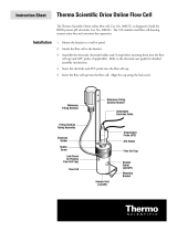
Electrode Installation into the Flow Cell,
Cat. No. 2001FC
The flow cell housing needs to be cleaned and installed into an
appropriate area with its mounting bracket. The reference filling
solution bracket and clip should be assembled on the flow cell
cap before installing the electrode. See the flow cell instruction
sheet for details.
Figure 3 – ROSS Electrode with Electrode Holder and O-ring
Side
Arm
Screw
Cap
Sensing
Element
Reference
Junction
Electrode
Holder
Holder
Screw
Electrode
Holder
Holder
Screw
O-Ring
FIG 3
O-Ring

6ROSS® Process pH Electrode User Guide
1. Take the electrode holder and slide the holder screw onto it
with the thread side down. The screw should be just below
the notch on the holder. See Figure 3.
2. Take the electrode holder and screw and slide it all the way
onto the electrode. The top of the holder should touch the
bottom of the electrode cap, and the sidearm should fit into
the notched area. See Figure 3.
3. Slide the large black O-ring onto the electrode up to the
bottom of the holder. See Figure 3.
4. Insert the holder with electrode, into the flow cell cap.
See Figure 4.
Figure 4 – Assembled Flow Cell Cap with Sensors
Reference
Filling Solution
Detachable
Electrode Cable
Flow Cell Cap
Reference Filling
Solution Bracket
Filling Solution
Tubing Assembly
Electrode
Holder
Holder
Screw
Sensing
Element
ATC Probe
ATC Holder
Temperature
Probe (ATC)
FIG 4

7ROSS® Process pH Electrode User Guide
5. Align the sidearm 180 degrees away from the bracket
holding the reference filling solution to insure correct
positioning of the reference junction.
6. Hold the electrode in position while screwing the holder
into the flow cell cap until finger tight. Do not overtighten.
7. Invert the filling solution bottle and insert it into the bottle
holder. Use the supplied pushpin to puncture three air
vents into the inverted bottom of the bottle. Venting the
bottle will help to avoid noisy and drifting output signals.
8. Mark the level of the solution in the bottle and note the
date. The solution level should be checked regularly and
replaced as required.
9. For inserting an optional ATC probe, take the ATC holder
and slide onto the ATC probe until it is under the ATC cap.
Take the smaller black O-ring and slide onto the ATC probe
until it fits snugly against the ATC holder. Place this ATC
assembly into the flow cell cap and turn the screw on the
holder until finger tight.
10. If no ATC probe is to be used, place the smaller black O-ring
into the ATC probe well on the flow cell cap. Take the ATC
holder and screw on until finger tight.
11. Take the flow cell cap assembly and gently place it straight
into the flow cell housing. The assembled cap needs to be
firmly placed straight into the cell. Do not tap the sensing
electrode against the flow cell housing.
12. Twist the cap so that the lock screw is aligned with the
notch on the cap and tighten the lock screw to position the
cap properly on the flow cell housing.
Flow Cell Cautions
When removing the cap from the flow cell, always unscrew
the lock screw first. Slowly pull the cap straight up from the
housing. Do not hit the sensing element against the housing.
When removing the electrode or ATC from the flow cell cap,
unscrew the holder screw or ATC holder first. Do not pull the
electrode or ATC out of the holder without first removing the
O-rings. Be careful not to lose the O-rings.
When placing the cap with assembled electrode into the flow
cell, place it in straight. Do not hit the sensing element against
the housing.

8ROSS® Process pH Electrode User Guide
Figure 5 – Assembled Flow Cell with Sensors
Flow Cell
Sample
Outlet
(3/8 NPT)
Mounting
Bracket
Sample Inlet
(1/8 NPT)
Lock Screw
(to Position
Flow Cell Cap)
Reference
Filling Solution
Detachable
Electrode Cable
Flow Cell Cap
Reference Filling
Solution Bracket
Filling Solution
Tubing Assembly
Electrode
Holder
Holder
Screw
ATC Holder
Temperature
Probe (ATC)
FIG 5

9ROSS® Process pH Electrode User Guide
Attaching the Electrode to a Monitor
Attach the 2001SC ROSS process pH electrode to the monitor
or amplifier using the interface cable, Cat. No. 2001EC.
1. Attach the screw cap end of the cable to the electrode.
2. Attach the stripped, unterminated ends to the monitor.
Refer to the monitor user guide for more detail. The
stripped, unterminated ends are easily identified and can be
inserted to any monitor’s terminal strip.
Figure 6 – Electrode Connector (Stripped Unterminated Ends)
Transparent Wire
(pH)
Black Wire
(Ref)
FIG 7
Assistance
After troubleshooting all components of your measurement
system, contact Technical Support. Within the United States call
1.800.225.1480 and outside the United States call 978.232.6000
or fax 978.232.6031. In Europe, the Middle East and Africa,
contact your local authorized dealer. For the most current
contact information, visit www.thermo.com/contactwater.
Warranty
For the most current warranty information,
visit www.thermo.com/water.

10 ROSS® Process pH Electrode User Guide
For Best Measurement Results
To maintain optimal electrode performance, use the following
guidelines.
• Check electrode slope by performing two buffer calibration.
Slope should be 92 to 102%.
• Always use fresh pH buffers when calibrating. Choose
buffers that are no more than three pH units apart. For
detailed calibration and temperature compensation
procedures, consult the monitor user guide.
• Use only ROSS reference filling solution, Cat. No. 2001FS.
Use of other filling solutions may result in electrode failure.
• Inspect the electrode for scratches, cracks, salts or other
deposits on the sensing element or reference junction.
Rinse off any precipitate by rinsing the electrode with
distilled water.
• To reduce errors due to polarization, do not rub or wipe the
electrode sensing element.
• Best results will be achieved if the electrode is used with
the Orion flow cell, Cat. No. 2001FC.
• The first time a new electrode is installed, allow the
electrode to equilibrate for 1 hour up to 24 hours.
• Change the reference filling solution tubing assembly once
every three to six months.
• Make sure that ROSS reference filling solution bottle is
properly vented.
• Periodically check that there is sufficient reference filling
solution and replace bottle as needed.
• Keep electrode and electrode holder areas clean.

11ROSS® Process pH Electrode User Guide
Ordering Information
Cat. No. Description
2001SC ROSS process combination pH electrode with
screw cap and sidearm
2001FC Flow cell for ROSS process pH electrode,
includes stainless steel housing with
mounting bracket, PVC holders and cap, and
solution mounting bracket
2001EC Detachable 1 meter cable for ROSS process
pH electrode, coaxial cable with screw cap
attachment for electrode and tinned, stripped,
unterminated ends for attachment to monitor
20015M Detachable 5 meter cable for ROSS process
pH electrode
2001XM Detachable 10 meter cable for ROSS process
pH electrode
2001CP 6 month consumables pack for ROSS process
pH electrode, includes 5 x 2 oz (60 mL) bottles
of ROSS filling solution and 1 pint (475 mL)
bottle each of pH 4.01, 7.00 and 10.01 buffers
2001FS ROSS reference filling solution for ROSS
process pH electrode, 5 x 2 oz (60 mL) bottles
910104 pH 4.01 buffer, 1 pint (475 mL) bottle
910107 pH 7.00 buffer, 1 pint (475 mL) bottle
910110 pH 10.01 buffer, 1 pint (475 mL) bottle
2001TP Process ATC temperature probe (30 kohm)
with 1 meter cable
2001XT Process ATC temperature probe (30 kohm)
with 10 meter cable
2001LN Process ATC temperature probe (8.5 kohm)
with 5 meter cable
2001TM Process ATC temperature probe (1 kohm) with
5 meter cable
2001EK ROSS process pH electrode kit, includes
ROSS electrode (2001SC), flow cell (2001FC),
ATC probe (2001XT) and cable (20015M)

12 ROSS® Process pH Electrode User Guide
Specifications
pH Range
0 to 14 pH
Temperature Range
0 to 100 °C
Drift
Less than 0.5 pH units for 30 days
Slope
92 to 102% (54.4 to 60.3 mV/dec)
Isopotential Point
pH 7
Junction
Ceramic frit
Internal Reference
ROSS
Size
Electrode Diameter: 12 mm
Electrode Length: 125 mm
Electrode Cap Diameter: 16 mm
Electrode Cap Length: 30 mm
Detachable Cable
Coaxial
Cable Length
1 meter
Filling Solution
ROSS reference filling solution
* Specifications are subject to change without notice

Thermo Fisher Scientific
Environmental Instruments
Water Analysis Instruments
166 Cummings Center
Beverly, MA 01915 USA
Tel: 978-232-6000
Toll Free: 800-225-1480
Dom. Fax: 978-232-6015
Int’l. Fax: 978-232-6031
www.thermo.com/water
255059-001 Rev.A
/