Page is loading ...


Software Version: 1.x
TA–193.204–ORE02 260201
AQUAfast, Cahn, ionplus, KNIpHE, ORION, PerpHecT, perpHecTion, Sens-
ing the future, SensorLink, Sure-Flow, Titrator PLUS and TURBO2 are reg-
istered trademarks of Thermo Orion.
1-888-pHAX-ION, All in One, AssuredAccuracy, AUTO-BAR, AUTO-CAL,
AUTO DISPENSER, AUTO-LOG, AUTO-STIR, AUTO-READ, Cable-Free,
CERTI-CAL, CISA, DataCOLLECT, digital LogR, DirectCal, DuraProbe,
Extra Easy/Extra Value, FAST QC, GLPcal, GLPcheck, GLPdoc, Ionalyzer,
KAP, KNIpHE, LogR, Minimum Stir Requirement, MSR, NISS, One-Touch,
One-Touch Calibration, One-Touch Measurement, Optimum Results, PEN-
Pal, pHISA, pHix, Phuture, Pure Water, QuicKcheK, rf link, ROSS, ROSS
Resolution, Sage, SAOB, Stat Face, The Enhanced Lab,ThermaSense,
Triode, TRIUMpH, Unbreakable pH, Universal Access and Wine Master are
trademarks of Thermo Orion.
Guaranteed Success and The Technical Edge are service marks of
Thermo Orion.
PerpHecT meters are protected by U.S. patent 4,321,544. Other patents
pending.
ROSS and PerpHecT ROSS are protected by U.S. patent 4,495,050. Other
patents pending.
ORION Series A meters and 900A printer are protected by U.S. patents
5,108,578, 5,198,093, D334,208, D346,753.
ORION 81, 82, 91, and 92 series glass electrodes are protected by U.S.
patents 4,661,236 and 4,687,500.
Sure-Flow electrodes are protected by European patent 278,979 and Cana-
dian patent 1,286,720. Other patents pending.
ionplus electrodes and Optimum Results solutions have patents pending.
E Copyright 1999, Thermo Orion. All rights reserved.
The specifications, descriptions, drawings, ordering information and part
numbers within this document are subject to change without notice.
This publication supersedes all previous publications on this subject.

Models 135A and 136S Portable Conductivity Meters
Information III
Safety Precautions
Be sure to read and follow these instructions !
The Model 136S Conductivity Meters may only be opened
to change the batteries outside hazardous areas. If repairs
are necessary, the meter must be sent in to the factory.
Never operate the remote interface or printer within haz-
ardous areas.
When using the meter in hazardous areas, watch for elec-
trostatic charges! For example, never wipe off the meter
with a dry cloth. Observe the relevant regulations concern-
ing ESD.
Whenever it is likely that the protection has been impaired, the meter shall
be made inoperative and secured against unintended operation.
The protection is likely to be impaired if, for example:
❏ the meter shows visible damage
❏ the meter fails to perform the intended measurements
❏ after prolonged storage at temperatures above 70 °C
❏ after severe transport stresses
Before recommissioning the meter, a professional routine test according to
EN 61 010-1 shall be performed. This test should be carried out at our fac-
tory.

cal
Note
Warning
Information IV
Information on this Instruction Manual
ITALICS are used for texts which appear in the display of
Thermo Orion Model 135A or 136S.
Bold print is used to represent keys, e.g. cal.
Display examples
or
keys whose functions are explained are frequently shown
in the left-hand column.
Notes provide important information which should always
be observed when using the meter.
Warning means that the instructions given must always be
followed for your own safety. Failure to follow these
instructions may result in injuries.

Models 135A and 136S Portable Conductivity Meters
Contents V
Contents
Safety Precautions III. . . . . . . . . . . . . . . . . . . . . . . . . . . . . . . . . . . . . . . . . . . . .
Information on this Instruction Manual IV. . . . . . . . . . . . . . . . . . . . . . . . . .
1 The Models 135A and 136S Conductivity Meters 1. . . . . . . . . . . . . . .
Package Contents 1. . . . . . . . . . . . . . . . . . . . . . . . . . . . . . . . . . . . . . .
Short Description of Meters 1. . . . . . . . . . . . . . . . . . . . . . . . . . . . . . .
2 Operation 3. . . . . . . . . . . . . . . . . . . . . . . . . . . . . . . . . . . . . . . . . . . . . . . . . .
Meter Design 3. . . . . . . . . . . . . . . . . . . . . . . . . . . . . . . . . . . . . . . . . . . .
Display 4. . . . . . . . . . . . . . . . . . . . . . . . . . . . . . . . . . . . . . . . . . . . . . . . .
Keypad 4. . . . . . . . . . . . . . . . . . . . . . . . . . . . . . . . . . . . . . . . . . . . . . . . .
Connection and Start-up 6. . . . . . . . . . . . . . . . . . . . . . . . . . . . . . . . . .
Configuration 8. . . . . . . . . . . . . . . . . . . . . . . . . . . . . . . . . . . . . . . . . . . .
Calibration 11. . . . . . . . . . . . . . . . . . . . . . . . . . . . . . . . . . . . . . . . . . . . . .
Measurement 15. . . . . . . . . . . . . . . . . . . . . . . . . . . . . . . . . . . . . . . . . . .
Data Log Memory 17. . . . . . . . . . . . . . . . . . . . . . . . . . . . . . . . . . . . . . . .
Data Log 18. . . . . . . . . . . . . . . . . . . . . . . . . . . . . . . . . . . . . . . . . . . . . . .
Clock Mode 20. . . . . . . . . . . . . . . . . . . . . . . . . . . . . . . . . . . . . . . . . . . . .
Serial Interface 21. . . . . . . . . . . . . . . . . . . . . . . . . . . . . . . . . . . . . . . . . .
Standard Setting for PRT300 Printer 22. . . . . . . . . . . . . . . . . . . . . . .
Configuring the PRT300 Printer 22. . . . . . . . . . . . . . . . . . . . . . . . . . . .
Printing Measured Values and GLPdoct Report 23. . . . . . . . . . . . .
3 Troubleshooting and Maintenance 24. . . . . . . . . . . . . . . . . . . . . . . . . . .
Error Messages 24. . . . . . . . . . . . . . . . . . . . . . . . . . . . . . . . . . . . . . . . .
Maintenance 27. . . . . . . . . . . . . . . . . . . . . . . . . . . . . . . . . . . . . . . . . . . .
Changing batteries 27. . . . . . . . . . . . . . . . . . . . . . . . . . . . . . . . . . . . . .
Cleaning the meter 28. . . . . . . . . . . . . . . . . . . . . . . . . . . . . . . . . . . . .

Contents VI
Appendix 29. . . . . . . . . . . . . . . . . . . . . . . . . . . . . . . . . . . . . . . . . . . . . . . . . . . . . .
Declarations of Conformity 29. . . . . . . . . . . . . . . . . . . . . . . . . . . . . . . .
Certificate of Conformity 31. . . . . . . . . . . . . . . . . . . . . . . . . . . . . . . . . .
Control Drawing 33. . . . . . . . . . . . . . . . . . . . . . . . . . . . . . . . . . . . . . . . .
Ordering Information 35. . . . . . . . . . . . . . . . . . . . . . . . . . . . . . . . . . . . .
Specifications 39. . . . . . . . . . . . . . . . . . . . . . . . . . . . . . . . . . . . . . . . . . .
Specifications for PRT300 Printer 40. . . . . . . . . . . . . . . . . . . . . . . . . .
Warranty 41. . . . . . . . . . . . . . . . . . . . . . . . . . . . . . . . . . . . . . . . . . . . . . .
Technical Terms 44. . . . . . . . . . . . . . . . . . . . . . . . . . . . . . . . . . . . . . . . . . . . . . . .
Index 46. . . . . . . . . . . . . . . . . . . . . . . . . . . . . . . . . . . . . . . . . . . . . . . . . . . . . . . . . .

Models 135A and 136S Portable Conductivity Meters
Models 135A and 136S 1
1 The Models 135A and 136S
Conductivity Meters
Package Contents
Please check the completeness of the shipment after un-
packing.
The package should include:
❏Thermo Orion Model 135A or 136S Conductivity Meter
(ready for operation)
❏Neck strap
❏This instruction manual
❏Quickstart instructions
❏Interface cable with adapter for printer and PC
❏PC software
Short Description of Meters
❏The Models 135A and 136S measure conductivity, sali-
nity, TDS and temperature in industry, the environment,
food processing and waste-water treatment.
❏Operation of the Model 136S is also permitted in Zone 1
hazardous areas.
❏The meters meet the European EMC regulations
(89-336-EEC) and the recommendations of NAMUR
NE 21.
❏The meters are IP 66 protected to EN 60 529.

Warning
Models 135A and 136S 2
❏Temperature compensation is automatic with a conducti-
vity probe with integral temperature sensor or a sepa-
rate ATC probe, or the temperature may be manually
entered.
❏Calibration can be carried out by directly entering the
cell constants, by calibrating with Thermo Orion Con-
ductivity Standards, or with any other buffer solutions.
❏The data log records up to 100 measured values with
the temperature, date and time. Recording takes place
either manually, interval or event-controlled.
❏To minimize battery consumption, the meter switches off
after either one or twelve hours when it is not operated.
❏Only three alkaline AA batteries are required for uninter-
rupted operation for approx. 1,000 hours.
❏PC software allows complete remote control of the me-
ter via PC. All measured values and parameters can be
read out and easily processed further (e.g. using Micro-
soft Excel).
❏Measured values and GLPdoct can also be sent di-
rectly to a printer via the serial interface.
Never use the remote interface to PC or printer in hazard-
ous areas!


power
meas
Note
cal
Operation 4
Display
Battery
empty Press
cal key Wait
Manual
temperature
detection
Temperature
detection
using NTC
Write
memory
Read
memory
Slope
(cell
constant)
Clock
Main
display
Secondary
display
Measure-
ment units
Error
message
Keypad
Pressing the power key switches the meter on or off.
After switching on, the meter automatically performs a
self-test and checks for the presence of a temperature
probe. Then it goes into the measuring mode.
Pressing the meas key returns the meter to the measur-
ing mode from any function. Pressing the meas key in the
measuring mode displays the following parameters:
Cond measuring mode: temperature compensation
tdS measuring mode: TDS factor
You can also power the meter up using the meas key.
However, only an abbreviated self-test is performed.
Pressing the cal key starts calibration.

Y B
clock
STO
RCL
print
RCL +print
cal +print
STO +clock
STO
+
clock
cal +power
Note
Models 135A and 136S Portable Conductivity Meters
Operation 5
With the Y and B keys you can select and change parame-
ters and select a mode.
Pressing the clock key switches the meter into the clock
mode. All measurement processes are cancelled and the
battery consumption is reduced to a minimum.
Pressing the STO key activates the data logger for writing
measured values.
Pressing the RCL key activates the data logger for reading
measured values.
Pressing the print key sends the currently measured
value to a printer or PC.
Pressing the RCL and print keys prints out the logged
data in memory.
Pressing the cal and print keys prints out the GLPdoct
report.
Pressing the STO and clock keys switches the meter
into the data logger mode.
Pressing the clock and STO keys activates the mode for
setting the date and time.
Pressing the cal and power keys when the meter is
switched off, activates the configuration menu.
When pressing two keys simultaneously, make sure that
the key shown at the left is pressed first.

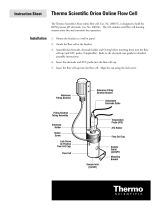
Connecting
sensor
Connection
assignment
Operation 6
Connection and Start-up
The following sensors from the line of accessories can be
connected to the meter.
013610 4-electrode epoxy/graphite sensor
with integrated temperature probe,
3 meter cable
K = 0.55 /cm
013660 4-electrode epoxy/graphite sensor
with integrated temperature probe,
20 meter cable
K = 0.55 /cm
Connection Socket. . . . . . . . . . . . . . . . . . . . . . . . . . .
Sensor 1. . . . . . . . . . . . . . . . . . . . . . . . . . . . . . . . . . . . .
Separate temperature probe 2, 3. . . . . . . . . . . . . . .
Interface 4. . . . . . . . . . . . . . . . . . . . . . . . . . . . . . . . . . .
1234
NTC
V–V+
I+
Shield
NTC
I–
V+
V–
I–
I+
If no temperature probe is used for measurement, the me-
ter operates with the manually set temperature and man
appears in the display.

Note
Note
Note
Note
power
Note
Note
Models 135A and 136S Portable Conductivity Meters
Operation 7
When using a sensor with temperature probe, an external
temperature probe may not be connected simultaneously.
If the meter is connected to a PC and is used to take mea-
surements in a grounded liquid, measuring errors may
result.
Prior to first use, the cell constant, temperature compensa-
tion and time and date must be checked and set, if re-
quired.
The calibration and configuration data and the contents of
the data log remain permanently stored both with the meter
switched off and with the batteries removed (battery re-
placement).
Pressing the power key switches the meter into measur-
ing mode.
When switched on, the meter determines the connected
temperature probe and conducts a self-test:
❏Simultaneous appearance of all display segments
❏Display of the model number
❏Display of the software version
For recognition of the temperature probe, the conductivity
sensor must be connected to the meter before power-up.
The meter can also be switched on with the meas key.
However, only an abbreviated test is performed. The meter
assumes that the last temperature probe determined is
used.

cal +power
meas
Function
Operation 8
Configuration
The following basic settings can be changed in the configu-
ration:
❏Function Cond (conductivity), SAL (salinity) or tdS (Total
Dissolved Solids)
❏Calibration by entering the cell constants (AutCal Off) or
calibration with Thermo Orion Conductivity Standards
(AutCal On)
❏Autoshutoff after
1 hour or 12 hours
❏Remote interface
Printer output On/Off, baud rate
❏Temperature display
°C or °F
❏Date and time format
24 hours and day, month, year or
12 hours (a.m./p.m.) and month, day, year
To activate the configuration hold down the cal key with
the meter switched off and then press the power key.
The menu items of the configuration menu are worked
through in sequence. Press the Y or Bkey to change the
setting of the respective menu item. The STO key saves
the parameters and switches to the next menu item.
Pressing the meas key exits the configuration menu at
any time. The value last displayed will not be saved unless
the STO key was pressed.
Select the measuring function Cond (conductivity), SAL
(salinity) or tdS (Total Dissolved Solids).

Automatic
or manual
calibration
Autoshutoff
Interface
Models 135A and 136S Portable Conductivity Meters
Operation 9
Select whether you wish to manually set the cell constant
or calibrate using Thermo Orion Conductivity Standards
and automatic drift check.
(Default setting: Direct entry of the cell constant [AutCAL
OFF])
Direct entry of the cell constants (AutCal OFF) from
0.010 cm–1 to 199.9 cm–1.
(Default setting 0.475 cm–1)
Automatic calibration (AutCAL On) with 0.1 molar KCl solu-
tion (Thermo Orion 12.9 mS Conductivity Standard,
Cat. no. 011006), 0.01 molar KCl (Thermo Orion 1413 mS
Conductivity Standard, Cat. no. 011007) or entry of the
temperature-compensated conductivity of another known
calibration solution.
To protect the batteries, the meter switches off automati-
cally when not operated for a longer time than specified.
You can select whether shut-off is to take place after one
hour or after twelve hours (default setting: 1 hour).
If the data logger is active and during remote interface
operation, the autoshutoff feature is disabled.
If the meter is controlled with a PC and interface conflicts
occur when the print key is pressed, the print function
should be deactivated (Print OFF).
(Default setting: Print On, 4,800 baud)
The transmission speed can be set to 600, 1,200, 2,400,
4,800 or 9,600 baud.
The transmission speed must correspond to that set in the
printer or PC.
The data format and protocol are permanently set to 7 bit,
one stop bit, even parity and XON/XOFF protocol
(NAMUR NE 28).


Calibration
solutions
Clean
sensors
Cell constant
4-electrode
sensors
2-electrode
sensors
Models 135A and 136S Portable Conductivity Meters
Operation 11
Calibration
With calibration the Models 135A and 136S are adjusted to
the cell constants of the sensor.
General information on calibration
Solutions for calibration of conductivity meters are un-
buffered systems. Care should be taken to use fresh
conductivity standards and to avoid contamination of the
conductivity standard by water droplets adhering to the
conductivity sensor.
Before calibration, make sure that the conductivity sensor
is clean. Residues should be rinsed off with distilled water.
Afterwards, the sensor should be wiped dry and rinsed with
the calibration solution to be used.
The cell constant is determined by the size and geometric
arrangement of the measuring electrodes. It is the charac-
teristic parameter of conductivity sensors. The cell cons-
tant changes very little over time.
With 4-electrode sensors the principle of separate current/
voltage electrodes results in virtually no measuring errors
even in the case of partial soiling of the measuring elec-
trodes. However, electrodes completely soiled with insulat-
ing coatings cause the measurement to fail.
With 2-electrode sensors for the measurement of low con-
ductivities, e.g. ultrapure water, calibration should be car-
ried out using Thermo Orion 100 mS Conductivity Standard
(Cat. no. 011008).

cal
Operation 12
Calibration by direct entry of the cell constants (AutCAL OFF)
Press the cal key to activate calibration. The cell constant
determined or set during the last calibration is displayed.
Pressing the meas key exits calibration again.
Set the cell constant of the sensor used with the Y and B
keys and confirm with the cal key. Then the meter
switches back into the measuring mode.

Note
cal
Models 135A and 136S Portable Conductivity Meters
Operation 13
Calibration with 0.1 or 0.01 molar KCl solution (AutCAL On)
(Thermo Orion 12.9 mS or 1413 mS Conductivity Standard)
Impurities must always be prevented from getting into the
calibration solutions.
Pressing the cal key activates calibration.
Calibration can be cancelled by pressing the meas key.
Then the cell constant of the last calibration is displayed
briefly.
Select the calibration solution used (CALSoL). A 0.1 and a
0.01 molar KCl solution are available to choose from. Con-
firm the corresponding solution with the cal key.
Immerse the clean and dry sensor in the calibration solu-
tion (also see “Clean sensors”, Pg. 11).
Press the cal key to start calibration. If calibration is not
desired, cancel the process with the meas key.
During calibration the lower line indicates the temperature.
The automatic drift check checks the stability of conductiv-
ity and temperature. The hour glass flashes.
When the measured values are stable, the temperature-
compensated table value of the KCl solution is displayed.
The measured conductivity value flashes.
Confirm with the cal key.
The determined cell constant is displayed for a few se-
conds. Then the meter switches back into the measuring
mode.

Note
cal
Operation 14
Calibration with any calibration solution (AutCAL ON)
Impurities must always be prevented from getting into the
calibration solutions.
Pressing the cal key activates calibration.
Calibration can be exited again with the meas key. Then
the cell constant of the last calibration is displayed briefly.
First confirm any of the 0.1 or 0.01 mol/l KCl solutions
(CALSoL) with the cal key.
Immerse the clean and dry sensor in the calibration solu-
tion (also see “Clean sensors” Pg. 11).
Press the cal key to start calibration. If calibration is not
desired, cancel the process with the meas key.
During calibration the lower line indicates the temperature.
The automatic drift check checks the stability of conductiv-
ity and temperature. The hour glass flashes.
When the measured values are stable, the temperature-
compensated table value of the KCl solution is displayed.
The measured conductivity value flashes.
See the table of your calibration solution for the conductiv-
ity value which belongs to the displayed measuring tem-
perature.
Set the temperature-compensated conductivity in the me-
ter with the Y and B keys, then confirm it with the cal
key.
The determined cell constant is displayed for a few se-
conds. Then the meter switches back into the measuring
mode.
/