Page is loading ...

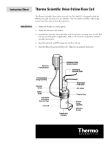
Analyze •Detect •Measure •Control™
Orion 95-02
Orion Carbon
Dioxide Electrode
INSTRUCTION MANUAL
CO2

AQUAfast, Cahn, EZ Flash, Ionalyzer, ionplus, KNIpHE, No Cal, ORION, perpHect,
PerpHecT, PerpHecTion, pHISA, pHix, pHuture, Pure Water, Sage, Sensing the
Future, SensorLink, ROSS Ultra, Sure-Flow, TEA Analyzer, Titrator PLUS, TURBO2
and Wine Master are registered trademarks of Thermo Electron Corporation.
1-888-pHAX-ION, A+, All in One, Aplus, AQUAsnap, AssuredAccuracy,
AUTO-BAR, AUTO-CAL, AUTO DISPENSER, Auto-ID, AUTO-LOG, AUTO-READ,
AUTO-STIR, Auto-Test, BOD AutoEZ, Cable-Free, CERTI-CAL, CISA, DataCOLLECT,
DataPLUS, digital LogR, DirectCal, DuraProbe, Environmental Product Authority,
Extra Easy/Extra Value, FAST QC, Flash Titration, Flash Titrator, GAP, GLPcal,
GLPcheck, GLPdoc, ISEasy, KAP, LabConnect, LogR, Low Maintenance Triode,
Minimum Stir Requirement, MSR, NISS, One-Touch, One-Touch Calibration, One-
Touch Measurement, Optimum Results, Pentrode, pHuture MMS, pHuture
Pentrode, pHuture Quatrode, pHuture Triode, Quatrode, QuiKcheK, rf link,
ROSS, ROSS Resolution, SAOB, Smart CheK, Stacked, Stat Face, The Enhanced
Lab, ThermaSense, Triode, TRIUMpH, Unbreakable pH, Universal Access are
trademarks of Thermo.
Guaranteed Success and The Technical Edge are service marks of Thermo.
PerpHecT meters are protected by U.S. patent 6,168,707.
PerpHecT ROSS are protected by U.S. patent 6,168,707.
ORION Series A meters and 900A printer are protected by U.S. patents
5,108,578, 5,198,093 and German patents D334,208 and D346,753.
Sure-Flow electrodes are protected by European Patent 278,979
and Canadian Patent 1,286,720.
ionplus electrodes and Optimum Results solutions are protected by
US Patent 5,830,338.
ROSS Ultra electrodes have patents pending.
ORION ORP Standard is protected by US Patent 6,350,367.
ORION Series A conductivity meters are protected by US Patent 5,872,454.
© Copyright 2003, Thermo Electron Corporation. All rights reserved. Question
everything, and Analyze.Detect.Measure.Control are trademarks of Thermo
Electron Corporation.
The specifications, descriptions, drawings, ordering information and part
numbers within this document are subject to change without notice.
This publication supersedes all previous publications on this subject.

1
CONTENTS
GENERAL INFORMATION 3
Introduction 3
Required Equipment 3
Required Solutions 4
USING THE ELECTRODE 5
Set up 5
Electrode Assembly and Preparation 5
Checking Electrode Operation (Slope) 6
Before Analysis 7
Units of Measurement 7
Sample Requirements 7
Sample Storage 8
Measuring Hints 8
Analytical Procedures 10
Analytical Techniques 10
Direct Calibration 10
Known Addition 13
Electrode Storage 17
TROUBLESHOOTING 18
Troubleshooting Checklist 18
Troubleshooting Guide 22
Assistance 24
ELECTRODE CHARACTERISTICS 25
Electrode Response 25
Reproducibility 25
Temperature Effects 25
Interferences 26
Effects of Dissolved Species 26
Theory of Operation 28
ACCESSORIES 31
WARRANTY INFORMATION 32
ORDERING INFORMATION 36
SPECIFICATIONS 37

2
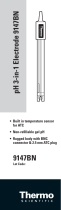
Tweezers
Carbon Dioxide Electrode
box of four with two O-rings
Membrane-Spacer Assemblies,
Figure 1
Contents Of Storage Box
Flip-top Spout
Internal Filling Solution,
50 mL bottle

3
GENERAL INFORMATION
Introduction
The Orion 95-02 Carbon Dioxide Electrode allows fast simple,
economical, and accurate measurements of carbon dioxide,
carbonate, and bicarbonate aqueous solutions. General analytical
procedures, required solutions, electrode characteristics, and
electrode theory are discussed in this manual. Operator
instructions for Orion Meters are outlined in the individual meter’s
instruction manual.
Our Technical Service Chemists can be consulted for assistance and
troubleshooting advice. Please refer to TROUBLESHOOTING for
information on contacting Orion.
Required Equipment
Meter
The easiest to use are direct concentration readout meters, such as
Orion EA 940, 920A, 720A, 710A or 290A. If unavailable, a pH/mV
meter with readability to 0.1mV, such as Orion 520A or 420A is
recommended.
Magnetic Stirrer
Recommended for laboratory measurements.
Graph Paper
4-Cycle semilogarithmic paper for preparing calibration curves (for
use with digital pH/mV laboratory meters).

4
Required Solutions
Distilled or Deionized Water - To prepare all
solutions and standards
Standard Solutions
Standard Solutions - 0.1 M Sodium Bicarbonate
Standard Solution
1000 ppm as CaCO3Standard Solution
1000 ppm as CO2Standard Solution - To
prepare, dilute 22.7 mL of 0.1 M standard,
Orion No. 950206, to 10 mL in a volumetric flask
Carbon Dioxide Buffer Solution - To adjust
solution pH to the operating range of the
electrode, 5 mL Carbon Dioxide Buffer must be
added to each 50 mL sample and
standard solution
Storage Solution - To store the electrode, 0.1 M
Sodium Chloride (NaCl)
Internal Filling Solution - To fill the electrode.
For inner body check:
pH 4.01 Buffer (with 0.1 M NaCl added) - for
checking inner body operation. Use Orion Buffer
(Orion No. 910104), or prepare 200 mL pH 4.00
buffer from Orion Buffer Powder (Orion No.
910004). Add 1.16 g reagent-grade NaCl to 100
mL of the buffer solution. Dissolve solid and
store the buffer for repeated use. Discard buffer
if turbidity develops
pH 7.00 Buffer (with 0.1 M NaCl added) - for
checking inner body operation. Use Orion Buffer
(Orion No. 910107), or prepare 200 mL pH 7.00
buffer from Orion Buffer Powder (Orion No.
910007). Add 1.16 g reagent-grade NaCl to 100
mL of the buffer solution. Dissolve solid and
store the buffer for repeated use. Discard buffer
if turbidity develops
Orion No.
950206
950207
Customer
prepared
950210
941706
950202
Customer
prepared
Customer
prepared

5
USING THE ELECTRODE
Set-Up
Electrode Assembly And Preparation
The electrode is shipped assembled, with a membrane in place for
packing. Disassemble the electrode as shown in step 1 of Figure 2,
and discard the membrane. Reassemble according to instructions in
Figure 2. After assembly the membrane should be slightly distended
by the inner body of the electrode. A membrane should last several
months, depending on usage. Membrane failure is characterized by a
shift in electrode potential, drift, and poor response.
See TROUBLESHOOTING.
top cap
vent hole
outer body
bottom cap
1. Remove top cap. Lift out inner body. Pour out old
internal filling solution. Remove bottom cap.
5. Fill outer body with internal
filling solution
6. Put inner body into outer body
Screw top cap on. Excess
will vent.
Figure 2 Electrode Assembly and Preparation
2. Remove O-ring and old
membrane assembly from cap.
3. Place membrane-spacer assembly in
the electrode with the white spacer ring
towards the inner sensing ring element
and the translucent membrane down
towards the sample solution.
O-ring
inner body
inner
sensing
element
reference
element
Fill to
here
red O-ring
membrane spacer
assembly
bottom cap
4. Place red O-ring in cap.
Screw body into bottom cap.

6
Checking Electrode Operation (Slope)
These are general instructions which can be used with most meters to
check electrode operation. See individual meter instruction manuals
for more specific information.
This procedure measures electrode slope. Slope is defined as the
change in millivolts observed with every tenfold change in
concentration. Obtaining the slope value provides the best means for
checking electrode operation.
1. Connect electrodes to the meter.
For an electrode with a U.S. Standard Connector: insert
the reference pin-tip connector and the sensing electrode
connector into appropriate jacks on the meter.
For an electrode with a BNC Connector: screw the connector
into the appropriate jack on the meter.
Non-Orion meters may require special adapters. Consult your
meter instruction manual.
Note that gas-sensing electrodes are placed in the electrode
holder so that they are at a 20° angle from the vertical.
This avoids trapping air bubbles at the tip of the electrode.
2. Place 45 mL distilled water and 5 mL carbon dioxide buffer into
a 100 mL beaker. Stir thoroughly. Set the function switch of the
meter to the mV mode.
3. Rinse electrode with distilled water and place in the solution
prepared in step 2 above.
4. Select either 0.1 M or 1000 ppm standard. Pipet 0.5 mL of the
standard into the beaker. Stir thoroughly. When a stable reading
is displayed, record the electrode potential in millivolts.
5. Pipet 5 mL of the same standard into the same beaker. Stir
thoroughly. When a stable reading is displayed, record the
electrode potential in millivolts.
6. The difference between the first and second potential reading is
defined as the slope of the electrode. The difference should be in
the range of 54-60 mV/decade when the solution temperature is
25° C. If the potential is not within this range, refer to
TROUBLESHOOTING.

7
Before Analysis
Units of Measurement
Carbon dioxide can be measured in units of moles per liter, parts per
million as carbon dioxide, parts per million as calcium carbonate, or
any other convenient concentration unit. See Table 1 for
conversion units.
Table 1
Concentration Unit Conversion Factors
Moles/Liter ppm as CO2ppm as CaCO3
10-4 4.4 10.0
10-3 44.0 100.0
10-2 440.0 1000.0
Sample Requirements
Samples must be aqueous. Samples and standards should be at the
same temperature. A 1°C difference in temperature will give rise to
about a 2% measurement error.
In all analytical procedures, carbon dioxide buffer solutions must be
added to samples and standards before measurement. After addition
of the buffer solution, all samples and standards should fall within the
pH 4.8 to 5.2 range so that all bicarbonate and carbonate is converted
to carbon dioxide and so that possible interferences are minimized.
Since the buffering capacity of the acid buffer is limited, highly basic,
highly acidic, or buffered samples must be adjusted to pH 4.8 - 5.2
before the carbon dioxide buffer is added.
The addition of buffer solution also adjusts the total level of dissolved
species in solution to 0.4 M. If the total level of dissolved species is
greater than 1 M after the addition of carbon dioxide buffer, the
sample should be diluted before measurement. See Effects of
Dissolved Species.

8
Sample Storage
If possible, samples should be measured at once, waiting only a
sufficient time for the sample to come to the temperature of the
electrode. In an open 150 mL beaker at 25° C, carbon dioxide
diffuses out of an acidic solution at a rate of about 3% per minute
with stirring and 0.5% without stirring. At higher temperatures the
rate of CO2loss increases. If solutions must be stored, make them
slightly alkaline (pH 8-9) by adding 10N NaOH* and storing them in a
tightly capped vessel to prevent pick-up of CO2from the air. Just
before measurement, acidify these stored samples with carbon
dioxide buffer.
*The amount of NaOH needed to adjust the pH will depend upon
the sample pH and buffering capacity. For unbuffered samples in
the slightly acidic range, 1 mL of 10N NaOH per 100 mL of
sample will be sufficient. NaOH should not be used to store
samples containing less than 100 ppm CO2since carbonate is
usually collected in a stoppered glass bottle. Fill the bottle
completely and cap tightly to prevent loss of CO2.
Measuring Hints
Minimize CO2loss from samples by:
-Measuring samples as soon as possible after collection.
-Storing samples according to Sample Storage.
-Minimizing the ratio of surface area to volume in the beaker.
-Keeping beakers containing standards and samples covered
between measurements according to Sample Storage.
-Adding carbon dioxide buffer just before measurement.
-Stir all standards and samples at a uniform rate during
measurement. Magnetic stirrers may generate sufficient heat to
change solution temperature. Place a piece of insulating
material such as cork, cardboard, or styrofoam between the
stirrer and beaker.
-Verify calibration every two hours by placing electrodes in the
first standard solution used for calibration. If the value has
changed, recalibrate.
-Always use fresh standards for calibration.

9
50
0
-50
100
10 100 1000
ppm as CO2
110100 1000
10 10 10
-4 -3 -2
~56 mV
electrode
potential
(mV)
ppm as CaCo3
molarity
Figure 3
Typical Response Of The Carbon Dixoide Electrode
10-fold change
-Always rinse electrodes with distilled water between
measurements (see Electrode Preparation). Shake after rinsing
to prevent solution carry over. Blot dry. Do not wipe or rub the
sensing membrane.
-Allow all standards and samples to come to room temperature
for precise measurement.
-After immersion in solution, check electrode for any air bubbles
on membrane surface and remove.

10
Analytical Procedures
Analytical Techniques
A variety of analytical techniques are available to the analyst.
The following is a description of these techniques.
Direct Calibration is a simple procedure for measuring a large
number of samples. Only one meter reading is required for each
sample. Calibration is performed in a series of standards. The
concentration of the samples is determined by comparison to the
standards. ISA is added to all solutions to ensure that samples and
standards have similar ionic strength.
Incremental Techniques provide a useful method for measuring
samples, since calibration is not required. As in direct calibration, any
convenient concentration unit can be used. The different incremental
techniques are described below. They can be used to measure the
total concentration of a specific ion in the presence of a large
(50-100 times) excess of complexing agents.
Known Addition is an alternate method useful for measuring
dilute samples, checking the results of direct calibration (when
no complexing agents are present), or measuring the total
concentration of an ion in the presence of an excess complexing
agent. The electrodes are immersed in the sample solution and
an aliquot of a standard solution containing the measured
species is added to the sample. From the change in potential
before and after the addition, the original sample
concentration is determined.
Direct Calibration
Set-up
1. Connect electrodes to the meter.
2. Prepare two standards which bracket the expected sample
range and differ in concentration by a factor of ten. Standards
can be prepared in any concentration unit to suit the particular
analysis requirement. All standards should be at the same
temperature as the samples. (For details on temperature effects
on electrode performance, refer to Temperature Effects.)

11
If using a meter with direct concentration readout capability
See individual meter instruction manuals for more specific
information.
1. Measure 50 mL of the more dilute standard into a 150 mL
beaker. Add 5 mL carbon dioxide buffer. Stir thoroughly.
2. Rinse electrodes with distilled water, blot dry and place into the
beaker. Wait for a stable reading, then adjust the meter to
display the value of the standard as described in the meter
instruction manual.
3. Measure 50 mL of the more concentrated standard into a
second 150 mL beaker. Add 5 mL carbon dioxide buffer.
Stir thoroughly.
4. Rinse electrodes with distilled water, blot dry and place into the
beaker with more concentrated standard. Wait for a stable read
ing, then adjust the meter to display the value of the second
standard, as described in the meter instruction manual.
5. Measure 50 mL of the sample into a 150 mL beaker. Add 5 mL
carbon dioxide buffer. Stir thoroughly. Rinse electrodes with
distilled water, blot dry and place into sample. The concentration
will be displayed on the meter.

12
If using a meter with millivolt readout only
1. Adjust the meter to measure mV.
2. Measure 50 mL of the more dilute standard into a 150 mL
beaker. Add 5 mL carbon dioxide buffer. Stir thoroughly.
3. Rinse electrodes with distilled water, blot dry and place into the
beaker. When a stable reading is displayed, record the mV value
and corresponding standard concentration.
4. Measure 50 mL of the more concentrated standard into a second
150 mL beaker. Add 5 mL carbon dioxide buffer. Stir thoroughly.
5. Rinse electrodes with distilled water, blot dry and place into the
second beaker. When a stable reading is displayed, record the
mV value and corresponding standard concentration.
6. Using semilogarithmic graph paper, prepare a calibration curve
by plotting the millivolt values on the linear axis and the standard
concentration values on the logarithmic axis.
7. Measure 50 mL of the sample into a 150 mL beaker. Add 5 mL
carbon dioxide buffer. Stir thoroughly.
8. Rinse electrodes with distilled water, blot dry and place into the
beaker. When a stable reading is displayed, record the mV value.
9. Using the calibration curve prepared in step 6, determine the
unknown concentration.

13
Known Addition
Known Addition is a convenient technique for measuring samples
because no calibration curve is needed. It can be used to verify the
results of a direct calibration or to measure the total concentration of
an ion in the presence of a large excess of a complexing agent. The
sample potential is measured before and after addition of a standard
solution. Accurate measurement requires that the following
conditions be met.
-Concentration should approximately double as a result of
the addition.
-Sample concentration should be known to within a
factor of three.
-In general, either no complexing agent or a large excess of the
complexing agent may be present.
-The ratio of the uncomplexed ion to complexed ion must not be
changed by addition of the standard.
-All samples and standards should be at the same temperature.
Set up
1. Connect electrodes to the meter.
2. Prepare a standard solution which, upon addition to the sample,
will cause the concentration of the carbon dioxide to double.
Refer to Table 2 as a guideline.
3. Determine the slope of the electrode by performing the
procedure under Checking Electrode Operation (Slope).
4. Rinse electrode between solutions with distilled water.
Table 2
Volume of Addition Concentration of Standard
1 mL 100 x sample concentration
5 mL 20 x sample concentration
10 mL* 10 x sample concentration
*Most convenient volume to use.

14
Known Addition Table for an added volume one-tenth the sample
volume. Slopes (in the column headings) are units of mV/decade
∆E Q1Concentration Ratio
Monovalent (57.2) (58.2) (59.2) (60.1)
5.0 0.2894 0.2933 0.2972 0.3011
5.2 0.2806 0.2844 0.2883 0.2921
5.4 0.2722 0.2760 0.2798 0.2835
5.6 0.2642 0.2680 0.2717 0.2754
5.8 0.2567 0.2604 0.2640 0.2677
6.0 0.2495 0.2531 0.2567 0.2603
6.2 0.2426 0.2462 0.2498 0.2533
6.4 0.2361 0.2396 0.2431 0.2466
6.6 0.2298 0.2333 0.2368 0.2402
6.8 0.2239 0.2273 0.2307 0.2341
7.0 0.2181 0.2215 0.2249 0.2282
7.2 0.2127 0.2160 0.2193 0.2226
7.4 0.2074 0.2107 0.2140 0.2172
7.6 0.2024 0.2056 0.2088 0.2120
7.8 0.1975 0.2007 0.2039 0.2071
8.0 0.1929 0.1961 0.1992 0.2023
8.2 0.1884 0.1915 0.1946 0.1977
8.4 0.1841 0.1872 0.1902 0.1933
8.6 0.1800 0.1830 0.1860 0.1890
8.8 0.1760 0.1790 0.1820 0.1849
9.0 0.1722 0.1751 0.1780 0.1809
9.2 0.1685 0.1714 0.1742 0.1771
9.4 0.1649 0.1677 0.1706 0.1734
9.6 0.1614 0.1642 0.1671 0.1698
9.8 0.1581 0.1609 0.1636 0.1664
10.0 0.1548 0.1576 0.1603 0.1631
10.2 0.1517 0.1544 0.1571 0.1598
10.4 0.1487 0.1514 0.1540 0.1567
10.6 0.1458 0.1484 0.1510 0.1537
10.8 0.1429 0.1455 0.1481 0.1507
11.0 0.1402 0.1427 0.1453 0.1479
11.2 0.1375 0.1400 0.1426 0.1451
11.4 0.1349 0.1374 0.1399 0.1424
11.6 0.1324 0.1349 0.1373 0.1398
11.8 0.1299 0.1324 0.1348 0.1373
12.0 0.1276 0.1300 0.1324 0.1348
12.2 0.1253 0.1277 0.1301 0.1324
12.4 0.1230 0.1254 0.1278 0.1301
12.6 0.1208 0.1232 0.1255 0.1278
12.8 0.1187 0.1210 0.1233 0.1256
13.0 0.1167 0.1189 0.1212 0.1235
13.2 0.1146 0.1169 0.1192 0.1214
13.4 0.1127 0.1149 0.1172 0.1194
13.6 0.1108 0.1130 0.1152 0.1174
13.8 0.1089 0.1111 0.1133 0.1155
14.0 0.1071 0.1093 0.1114 0.1136
14.2 0.1053 0.1075 0.1096 0.1118
14.4 0.1036 0.1057 0.1079 0.1100
14.6 0.1019 0.1040 0.1061 0.1082
14.8 0.1003 0.1024 0.1045 0.1065
15.0 0.0987 0.1008 0.1028 0.1048
15.5 0.0949 0.0969 0.0989 0.1009
16.0 0.0913 0.0932 0.0951 0.0971
16.5 0.0878 0.0897 0.0916 0.0935
17.0 0.0846 0.0865 0.0883 0.0901
17.5 0.0815 0.0833 0.0852 0.0870

15
∆E Q1Concentration Ratio
Monovalent (57.2) (58.2) (59.2) (60.1)
18.0 0.0786 0.0804 0.0822 0.0839
18.5 0.0759 0.0776 0.0793 0.0810
19.0 0.0733 0.0749 0.0766 0.0783
19.5 0.0708 0.0724 0.0740 0.0757
20.0 0.0684 0.0700 0.0716 0.0732
20.5 0.0661 0.0677 0.0693 0.0708
21.0 0.0640 0.0655 0.0670 0.0686
21.5 0.0619 0.0634 0.0649 0.0664
22.0 0.0599 0.0614 0.0629 0.0643
22.5 0.0580 0.0595 0.0609 0.0624
23.0 0.0562 0.0576 0.0590 0.0605
23.5 0.0545 0.0559 0.0573 0.0586
24.0 0.0528 0.0542 0.0555 0.0569
24.5 0.0512 0.0526 0.0539 0.0552
25.0 0.0497 0.0510 0.0523 0.0536
25.5 0.0482 0.0495 0.0508 0.0521
26.0 0.0468 0.0481 0.0493 0.0506
26.5 0.0455 0.0467 0.0479 0.0491
27.0 0.0442 0.0454 0.0466 0.0478
27.5 0.0429 0.0441 0.0453 0.0464
28.0 0.0417 0.0428 0.0440 0.0452
28.5 0.0405 0.0417 0.0428 0.0439
29.0 0.0394 0.0405 0.0416 0.0427
29.5 0.0383 0.0394 0.0405 0.0416
30.0 0.0373 0.0383 0.0394 0.0405
31.0 0.0353 0.0363 0.0373 0.0384
32.0 0.0334 0.0344 0.0354 0.0364
33.0 0.0317 0.0326 0.0336 0.0346
34.0 0.0300 0.0310 0.0319 0.0328
35.0 0.0285 0.0294 0.0303 0.0312
36.0 0.0271 0.0280 0.0288 0.0297
37.0 0.0257 0.0266 0.0274 0.0283
38.0 0.0245 0.0253 0.0261 0.0269
39.0 0.0233 0.0241 0.0249 0.0257
40.0 0.0222 0.0229 0.0237 0.0245
41.0 0.0211 0.0218 0.0226 0.0233
42.0 0.0201 0.0208 0.0215 0.0223
43.0 0.0192 0.0199 0.0205 0.0212
44.0 0.0183 0.0189 0.0196 0.0203
45.0 0.0174 0.0181 0.0187 0.0194
46.0 0.0166 0.0172 0.0179 0.0185
47.0 0.0159 0.0165 0.0171 0.0177
48.0 0.0151 0.0157 0.0163 0.0169
49.0 0.0145 0.0150 0.0156 0.0162
50.0 0.0138 0.0144 0.0149 0.0155
51.0 0.0132 0.0137 0.0143 0.0148
52.0 0.0126 0.0131 0.0136 0.0142
53.0 0.0120 0.0125 0.0131 0.0136
54.0 0.0115 0.0120 0.0125 0.0130
55.0 0.0110 0.0115 0.0120 0.0124
56.0 0.0105 0.0110 0.0115 0.0119
57.0 0.0101 0.0105 0.0110 0.0114
58.0 0.0096 0.0101 0.0105 0.0109
59.0 0.0092 0.0096 0.0101 0.0105
60.0 0.0088 0.0092 0.0096 0.0101

16
If using an instrument with direct known addition readout capability
See individual meter instruction manuals for more
specific information.
1. Set up meter to measure in the known addition mode.
2. Measure 50 mL of the sample into a beaker. Rinse electrodes
with distilled water, place in sample solution. Add 5 mL
carbon dioxide buffer. Stir thoroughly.
3. When a stable reading is displayed, calibrate the meter as
described in the meter instruction manual.
4. Pipet the appropriate amount of the standard solution into the
beaker. Stir thoroughly.
5. When a stable reading is displayed, record the
sample concentration.
Analysis using a meter with millivolt readout only
Use this procedure when no instructions for known addition are
available in the meter instruction manual.
1. Set the meter to relative millivolt mode.
2. Measure 50 mL of the sample into a 100 mL beaker.
Add 5 mL carbon dioxide buffer. Stir thoroughly.
3. Rinse electrodes with distilled water, blot dry and place into
beaker. When a stable reading is displayed, set the reading
to 000.0. If the reading cannot be set to 000.0, record
the mV value.
4. Pipet the appropriate amount of standard solution into the
beaker. Stir thoroughly.
5. When a stable reading is displayed, record the mV value.
If the meter could not be zeroed in step 3, subtract the first
reading from the second to find ∆E.

17
6. From Table 3, find the value, Q, that corresponds to the change
in potential, ∆E. To determine the original sample concentration,
multiply Q by the concentration of the added standard:
Csam = QCstd
where:
Cstd = standard concentration
Csam = sample concentration
Q = reading from known addition table
The table of Q values is calculated for a 10% volume change for
electrodes with slopes between 57.2 to 60.1 mV/decade. The
equation for the calculation of Q for different slopes and volume
changes is given below:
p
Q = (1+p)10 ∆E/S -1
where:
Q = reading from known addition table
∆E = E2 - E1
S = slope of the electrode
volume of standard
p = volume of sample
Electrode Storage
To store the electrode between samples, overnight or over a weekend,
immerse the electrode tip in a 0.1M NaCl storage solution. If the
electrode is not to be used for longer periods of time, completely
disassemble and rinse inner body, outer body, and cap with distilled
water. Dry and reassemble electrode without filling solution.

18
TROUBLESHOOTING
Troubleshooting checklist
Symptom Possible cause
Off Scale or Defective meter
Over-range reading
Defective inner body
Electrodes not plugged in properly
Internal filling solution not added
Air bubble on membrane
Electrodes not in solution
Noisy or unstable Insufficient internal filling solution
readings (erratic-
rapidly changing)
Defective meter
Bottom cap loose
Defective inner body
Carbon dioxide buffer not used
Meter stirrer improperly grounded
Drift (reading Internal filling solution leakage
slowly changing in
one direction) Incorrect internal filling solution
Total level of dissolved species above 1M
Electrode in sample too long; CO2loss
Membrane failure (wet,
perforation, discoloration)
Solutions not at constant temperature
Heat generated by magnetic stirrer
/