Page is loading ...

Hardened 1-
port 10/100BaseTX
to 100BaseFX Media Converter
User's Manual
(V1.1 Version)
065-1800ATB
065-1810ATB
065-1820ATB

Overview
The
Signamax
065
-
1800ATB/065
-
1810ATB/065
-
1820ATB
are
Hardened
1-port 10/100BaseTX to 100BaseFX Media Converters that provide
a cost-effective solution, and are specially designed for reliable and stable
operation in industrial environments.
Package Checklist
Signamax
’s
065
-
1800ATB/065
-
1810ATB/065
-
1820ATB
are
shipped with
the following items. If any of these items are missing or damaged,
please contact your customer service representative for assistance.
•
•
•
065
-
1800ATB/065
-
1810ATB/065
-
1820ATB
media converter
x 1
User's Manual (CD format) x1
Warranty card x1
Features
•
•
•
•
Converts 100
Base
TX to 100
Base
FX
IEEE 802.3/802.3u/802.3x,store and forward
Plug-and-play, easy installation
Full/Half duplex, MDI/MDI-X auto negotiation
•
•
•
IP40 protection,
a
luminum
a
lloy
case
Extensive LED indicators for network diagnostics
Environmentally hardened -40°F to 176°F (-40°C to 80°C)
operating temperature
- 2 -

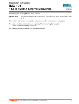
Panel Layout
1.
2.
Shielding Ground
Terminal block for power
input
3.
4.
5.
RUN LED
Power LED (PWR2)
Power LED (PWR1)
6.
7.
8.
Fiber LED (FX1)
RJ45 Ethernet Port
Fiber Port: SC/ST/SFP
connector
9.
DIN
rail kit
- 3 -
2
3
4
6
8
7
5
1
Front View
Top
View
Full
View
9

Mounting Dimensions
DIN Rail Mounting
The aluminum DIN rail attachment
plate should be fixed to the back
panel of the Converter when you
take it out of the box. If you need to
reattach the DIN rail attachment
plate to the Converter, make sure
the stiff metal spring is situated
towards the top.
Wiring Requirements
ATTENTION
Safety First!
Be sure to disconnect the power cord before installing and/or
wiring Signamax 065-1800ATB/065-1810ATB/065-1820ATB.
Calculate the maximum possible current in each power wire and
common wire. Observe all electrical codes dictating the
maximum current allowable for each wire size.
If the current
goes above the maximum rating, the wiring could
overheat, causing serious damage to your equipment.
•
Use separate paths to route wiring for power and devices. If power
wiring and device wiring paths must cross, make sure the wires are
perpendicular at the intersection point.
- 4 -

•
•
Do not run signal or communications wiring and power wiring in the
same wire conduit. To avoid interference, wires with different signal
characteristics should be routed separately.
You can use the type of signal transmitted through a wire to
determine which wires should be kept separate. The rule of thumb is
that wiring that shares similar electrical characteristics can be
bundled together.
•
•
Keep input wiring and output wiring separated.
We strongly advise that you label wiring to all devices in the system.
Grounding the Signamax 065-1800ATB/065-1810ATB/065-1820ATB
Grounding and wire routing help limit the effects
of noise due to electromagnetic interference
(EMI). Run the ground connection from the
ground screw to the grounding surface prior to
connecting devices.
ATTENTION
This product is intended to be mounted to a well
-
grounded
mounting surface such as a metal panel.
Wiring the Power Inputs
The
6
-
contact terminal block connector on the
Ind
ustrial Media Converter
’s
top panel is used for the Industrial Media Converter’s two DC inputs. Top
and front views of one of the terminal block connectors are shown here.
STEP 1:
Insert the negative/positive DC wires
into the V-/V+ terminals.
STEP 2:
To keep the DC wires from pulling loose,
use a small flat-blade screwdriver to tighten the
wire-clamp screws on the front of the terminal
block connector.
STEP 3:
Insert the plastic terminal block
connector prongs into the terminal block receptor
located on 065-1800ATB/065-1810ATB/065-1820ATB’s
top panel.
Redundant Power Inputs
Both power inputs can be connected simultaneously to live DC power
sources. If one power source fails, the other live source acts as a backup,
and automatically supplies all of the Industrial Media Converter’s
power needs.
- 5 -

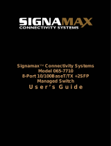
Communication Connections
RJ45 Ethernet Port Connection
When connected to a
10/100Mbps
Ethernet port, the pinouts and cable
wiring diagrams for both MDI (NIC-type) and MDI-X (HUB/switch-type)
ports for both straight-through and cross-over Ethernet cables are:
MDI-X Port Pinouts
8-pin RJ45
MDI Port Pinouts
Pin
1
2
Signal
Tx+
Tx-
Pin
1
2
Signal
Rx+
Rx-
The Signamax
065
-
1800ATB/065
-
1810ATB/065
-
1820ATB has one
Ethernet port located on the front panel for connecting to Ethernet-
enabled devices.
3
6
Rx+
Rx-
3
6
Tx+
Tx-
Straight
-
Through Cable Wiring
Cross
-
Over Cable Wiring
All you need to remember is to connect the Tx (transm
it) port of device I
to the Rx (receive) port of device II, and the Rx (receive) port of device I
to the Tx (transmit) port of device II. If you make your own cables, we
suggest labeling the two sides of the same line with the same letter
(A-to-A and B-to-B, as shown below, or A1-to-A2 and B1-to-B2).
The concept behind the SC
/ST
port and cable is straightforward.
Suppose you are connecting devices I and II. Contrary to electrical signals,
optical signals do not require a circuit in order to transmit data.
Consequently, one of the optical lines is used to transmit data from device
I to device II, and the other optical line is used transmit data from device
II to device I, for full-duplex transmission.
- 6 -
SC
/ST
Fiber Optic Port Connection

ATTENTION
This is a Class 1 Laser/LED product. To avoid causing serious
damage to your eyes, do not stare directly into the laser beam.
- 7 -

LED Indicators
The front panel of the Signamax 065
-
1800ATB/065
-
1810ATB/065
-
1820ATB contains several LED indicators. The function of each LED is
described in the table below.
Conection Diagram
Common Troubleshooting
Device is not matched. Please select the corresponding network
device according to the transfer rate
of the product (10Mbps or
100Mbps) when connected to other network devices (network
card, hub, switch).
Line loss is excessive during the fiber wiring. Excessive loss in
connector plug-in and fiber welding, and excessive intermediate
nodes may cause excessive loss rate or abnormal operation.
-
8
-

Technical Specifications
Applicable Standards: IEEE 802.3u
100BaseTX/FX
IEEE 802.3X Flow Control
Processing Type: Store and Forward
Half-duplex, Full-duplex
Forward Filter Rate: 148,800pps (100Mbps)
Cabling: 100BaseTX: Cat5 or
better
Maximum Distance: Cat5 UTP up to 100m
Connector: 1x RJ45
Optical Port: 100BaseFX, SC
connector
Environmental
Operating Temperature: -40°F to 176°F (-40°C to
80°C)
Storage Temperature: -40°F to 185°F (-40°C to
85°C)
Relative Humidity: 5% to 95% non-
condensing
Electrical and Mechanical
MTBF: > 300,000 hrs
Input Power: 24VDC (18~36VDC, 6-
Pin Terminal Block)
Power Consumption: 12W Max. 0.5A@24VDC
LED Indicators PWR: Power Status
RUN: Link/Activity, Speed
FX: Link/Activity
Dimensions (W x D x H): 4.41 x 5.43 x 1.65 inches
(112 x 138 x 42mm)
Weight: 1.06 lbs. (480 g)
Casing: Aluminum Case
Mounting Options: DIN-Rail mounting, Wall
mounting
-9 -

Regulatory Approvals
Safety: UL 60950-1
EMS:
EN61000-4-2 (ESD),Level 3,
EN61000-4-3 (RS),Level 3,
EN61000-4-4 (EFT),Level3,
EN61000-4-5 (Surge),Level 3,
EN61000-4-6 (CS),Level 3
Shock: IEC 60068-2-27
Free Fall: IEC 60068-2-32
Vibration: IEC 60068-2-6
EMI: FCC Part 15 Subpart B Class A,
EN 55022 Class A
Industry: IEC61000-6-2
Rail: EN50155, EN50121-4
Traffic: NEMA TS-2
- 10 -
/