Page is loading ...

RTA-RS232
Setup and Installation Guide
For RadioTouchTM RS232 Interface
A Comprehensive Step-by-Step Guide for Programming
and Operating the Lutron® RadioTouchTM RS232 Interface
Note: Please leave this manual with facility manager.
General
Lights
ON
OFF
RTA-RS232
Radio Frequency
Interface
Coopersburg, PA 18036
RadioTouch
TM
See the RTA-RS232 Setup Guide for interface
programming and operation instructions. For
additional system details consult the
RadioTouch
TM
Installers Guide, which is
included with each RadioTouch
TM
Controller.
RadioTouch is a trademark of Lutron Electronics Co., Inc.
This product may be covered by one or more of the following
U.S. patents: 5,248,919; 5,399,940; 5,736,965; 5,798,581;
5,838,226; 5,848,054; 5,905,442, 5,982,103
For additional assistance call the Lutron Technical
Support Center at
(800) 523-9466.
Left
Scroll
Mode
Address
PowerEnter
Power
9V
AC IN
Display
RS232 Connector
TX RX
Right
Scroll
OR
Optional Terminal
Block Connector
12
3
Common
Data In
Data Out
INTERFACE CONTROL
PELV(CLASS 2:USA)
Status
LED
P/N 500-9258 Rev A
Sivoia Cntrl 1
Sivoia Cntrl 2
RTA-RX-F-SC
Radio Frequency Controller
LISTED 243C
Ind. Cont. Eq.
Coopersburg, PA 18036
STATUS INDICATOR OPERATION
ON - Burn-in Mode
Slow Blink -Normal Operation Mode
Fast Blink - Program Mode
Very Fast Blink - Receiving RF Data
RadioTouch
12
345678910
11
12 13 14
15 16
Occ. Com
Signal
15V
24V
Circuit Com
Sw Closure 1
Sw Closure 2
Sw Closure 3
Sw Closure 4
Sw Closure 5
Closure Com
0-10 Purple
0-10 Gray
Receiver
Settings
Terminal connections
are Class 2.
TM
Occ. Sensor
0-10 V
Shade Sw itch Closures
12345
Powered
When Lit
Status
Indicator
Program
Button
Burn-in
Button
RECEIVER SWITCH SETTINGS
1. UP-Preset Lock DN.-Preset Adj.
2. UP-Occ. Sensor DN.-Emerg. Set.
3. UP-FDB Mode DN.-ECO Mode
4. UP-OFF DN.-Min. Light
5. UP-Auto ON DN.-Manual ON
See Installers Guide for System
Addressing and Programming Instructions
®
123
Shade
Settings
SHADE SWITCH SETTINGS
1. UP-A/C Shades DN.-Normal Oper.
PS Signal
© 2000-2002 Lutron Electronics Co., Inc.

Important Application Notes
The RadioTouchTM RS232 Interface is simply another transmitter in the RadioTouchTM System. The RS232
Interface has the ability to communicate with up to 10 unique zones of lights, Sivoia® shades, or contact closure
outputs in a single room. This device can not report the status of the lighting zones, Sivoia® shades, or contact
closure outputs back to the host RS232 device.
FCC Information
NOTE: This equipment has been tested and found to comply with the limits for a Class B digital device, pursuant to part 15 of the FCC rules. These limits are
designed to provide reasonable protection against harmful interference in a residential installation. This equipment generates, uses and can radiate radio
frequency energy and, if not installed and used in accordance with the instructions, may cause harmful interference to radio or television reception, which can
be determined by turning the equipment off and on. The user is encouraged to try to correct the interference by one or more of the following measures:
• Reorient or relocate the receiving antenna.
• Increase the separation between the equipment and receiver.
• Connect the equipment into an outlet on a circuit different from that to which the receiver is connected.
• Consult the dealer or an experienced radio/TV technician for help.
Caution: Changes or modifications not expressly approved by Lutron Electronics Co., Inc. could void the user's authority to operate this equipment.
Notes on this Manual
This manual is an addendum to the RadioTouchTM Installer’s Guide. The procedures to setup a RadioTouchTM
RS232 Interface is contained in this manual. For more information on programming the remainder of your
RadioTouchTM System, or for advanced features, refer to the RadioTouchTM Installers Guide (P/N 031-200).
This symbol is intended to alert the user to the presence of important installation and operating instructions.
Consumer Information
Danger
This RadioTouchTM system must not be used to control equipment, other than lighting, which is not visible from every
transmitter location. It also must not be used to control equipment which could create hazardous situations such as
entrapment if operated accidentally. Examples of equipment which must not be controlled by this RadioTouch
TM system
include (but are not limited to) motorized gates, garage doors, industrial doors, microwave ovens, heating pads, etc. It is the
installer's responsibility to ensure that the equipment, other than lighting, being controlled is visible from every transmitter
location and that only suitable equipment is connected to this RadioTouch
TM system.
RadioTouchTM Installers Guide for RTA-RS232

Table of Contents
RadioTouchTM Installers Guide for RTA-RS232 3
Section 1 - Installation
Overview of the RS232 Interface
Overview ........................................................................................................................................................... 4
Installing an RS232 Interface
Installation ........................................................................................................................................................ 5
Section 2 - Start-Up
Determine zone type and number .................................................................................................................. 8
Configuring zone types ................................................................................................................................... 9
Adding a zone on the RS232 Interface to a RadioTouch
TM Controller ........................................................ 11
Set data flow control method ......................................................................................................................... 14
Section 3 - Protocol
Notes on Protocol
............................................................................................................................................ 16
Command Summary
....................................................................................................................................... 20
Device Control Commands
PS – Go to a preset level ................................................................................................................................ 21
XC – Explicit Command .................................................................................................................................. 23
Table 1 – Explicit Zone Levels ........................................................................................................................ 23
BSTP – Begin Step .......................................................................................................................................... 24
ESTP – End Step .............................................................................................................................................. 24
PSA – Preset Adjust Mode .............................................................................................................................. 24
SPS – Set Preset .............................................................................................................................................. 25
PHC – Photosensor Calibration Mode ........................................................................................................... 25
PING .................................................................................................................................................................. 25
Configuration Commands
ENTER/EXIT Configuration Mode ................................................................................................................... 26
TYPE – Setting the Zone Type ........................................................................................................................ 26
RB – Turning Reply Back Mode ON or OFF .................................................................................................. 26
ACK – Turning Acknowledgments ON or OFF ..............................................................................................27
ADD/DELETE – Adding or Deleting the RTA-RS232 to/from RF Controllers.............................................. 27
RPT – Reporting Configuration Settings ....................................................................................................... 27
Monitoring Control
Prompt .............................................................................................................................................................. 28
CON – Configuration Reports ......................................................................................................................... 28
ERROR – Error Codes ..................................................................................................................................... 28
OK ..................................................................................................................................................................... 29
ACK ................................................................................................................................................................... 29
Section 4 - Advanced Programming
Deleting a zone on the RS232 Interface from a RadioTouchTM Controller .................................................. 30
Modifying Reply Back Settings ...................................................................................................................... 33
Modifying Acknowledgment Settings ............................................................................................................ 35
Section 5 - Operation
Setting up scenes that can be accessed and modified from a Tabletop or Wall Control for
single zone types ............................................................................................................................................. 37
Setting up Scenes that cannot be accessed from Tabletop or Wall Controls or that contain
multiple zone types ......................................................................................................................................... 39
Section 6 - Troubleshooting
Troubleshooting Guide
.................................................................................................................................. 40

RadioTouchTM Setup Guide for RTA-RS2324
Section 1 - Installation
Overview of the RS232 Interface
Overview
NOTE: The RS232 Interface will not operate
until it has been programmed.
• After 10 minutes with no button presses, the display
will turn OFF. To restore the display, press and
release any button on the RS232 Interface or send
an RS232 command.
TX RX
RTA-RS232
Radio Frequency
Interface
Coopersburg, PA 18036
RadioTouch
TM
See the RTA-RS232 Setup Guide for interface
programming and operation instructions. For
additional system details consult the
RadioTouch
TM
Installers Guide, which is
included with each RadioTouch
TM
Controller.
RadioTouch is a trademark of Lutron Electronics Co., Inc.
This product may be covered by one or more of the following
U.S. patents: 5,248,919; 5,399,940; 5,736,965; 5,798,581;
5,838,226; 5,848,054; 5,905,442, 5,982,103
For additional assistance call the Lutron Technical
Support Center at
(800) 523-9466.
Left
Scroll
Mode
Address
PowerEnter
Power
9V
AC IN
Display
RS232 Connector
TX RX
Right
Scroll
OR
Optional Terminal
Block Connector
12
3
Common
Data In
Data Out
INTERFACE CONTROL
PELV(CLASS 2:USA)
Status
LED
P/N 500-9258 Rev A
Display
Right Scroll
button scrolls
the right
Display
Power jack
Power LED
indicates
RTA-RS232
has power
Left Scroll
button scrolls
the left
Display
RS232
Connector
TX LED
flutters when
RTA-RS232
is
transmitting
any RS232
data
RX LED
flutters when
RTA-RS232
is receiving
any RS232
data
Address
button
Mode button
cycles through
modes of
operation
Enter button
selects
displayed
option
This manual contains information on how to setup and
install an RS232 Interface. It also contains information
regarding the RS232 command set and how to
interface the RTA-RS232 with equipment external to
the RadioTouchTM System.
The RTA-RS232 allows an external device, such as a
touch screen, to control RadioTouchTM lighting and
window shading loads.
The RadioTouchTM RS232 Interface is capable of
controlling 10 unique lighting, Sivoia® shading or
contact closure output zones in the RadioTouchTM
System.
Antenna for
Radio Frequency
communication

RadioTouchTM Setup Guide for RTA-RS232 5
Section 1 - Installation
Installing an RS232 Interface
Installation
Read all instructions completely before installation.
Step 1 Find a suitable location for the
RS232 Interface
Place the RS232 Interface in a convenient and
accessible location. Note: The RS232 Interface
must be located within 35 feet of all
RadioTouchTM Controllers in the room.
Step 2 Mount the RS232 Interface
Using two screws, mount the RS232 Interface
to a 4"x4" junction box or directly to a wall
(screws and wall anchors provided).
Mounting to
junction box
W
A
L
L
Mounting to
wall
Knockout Hole
W
A
L
L
4"x4" Junction Box
Use two screws for mounting.
Important Installation Notes
1. Install in accordance with all national and local
electrical codes.
2. Do not paint the RS232 Interface.
3. Operate in ambient temperatures between 0°C
(32°F) and 40°C (104°F).
4. Use only the AC adapter provided by Lutron with
your RS232 Interface unit. Using an AC adapter not
rated at the following specifications could damage
the control and possibly overheat the AC adapter.
• Input: AC 120V 60Hz
• Output: AC 9V/500mA Class 2
5. The range and performance of the RadioTouchTM
System is highly dependent on a variety of complex
factors such as:
• Distance between system components
• Construction of walls separating system
components
• Electrical equipment located near system
components
RTA-RS232
Radio Frequency
Interface
Coopersburg, PA 18036
RadioTouch
TM
See the RTA-RS232 Setup Guide for interface
programming and operation instructions. For
additional system details consult the
RadioTouchTM Installers Guide, which is
included with each RadioTouchTM Controller.
RadioTouch is a trademark of Lutron Electronics Co., Inc.
This product may be covered by one or more of the following
U.S. patents: 5,248,919; 5,399,940; 5,736,965; 5,798,581;
5,838,226; 5,848,054; 5,905,442, 5,982,103
For additional assistance call the Lutron Technical
Support Center at
(800) 523-9466.
Left
Scroll
Mode
Address
PowerEnter
Power
9V
AC IN
Display
RS232 Connector
TX RX
Right
Scroll
OR
Optional Terminal
Block Connector
12
3
Common
Data In
Data Out
INTERFACE CONTROL
PELV(CLASS 2:USA)
Status
LED
P/N 500-9258 Rev A
• Continued on next page.

RadioTouchTM Setup Guide for RTA-RS2326
Section 1 - Installation
Installing an RS232 Interface
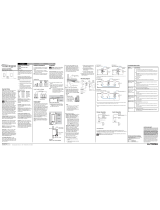
Step 4a Connect the RS232 cable
For 3 wire software flow control or no flow
control, connect the three (3) RS232 wires to
the connector as shown below.
RS232 wire must enter unit through a knockout
hole located on either side of the unit. Place the
provided grommet in the knockout hole before
wiring.
Power
TX RX
Common
Data In
Data Out
RS232 Terminal
Block
To External Device
To select the proper RS232 cable for your
application, see the RadioTouchTM RS232
Notes on Protocol (page 16).
Step 3 Attach the power supply
Remove terminal cover. Attach the power
supply cord to the RS232 Interface (jack
located in the bottom right corner). Power
supply cord must enter unit through a knockout
hole located on either side of the unit. Place the
provided grommet in the knockout hole before
wiring.
Remove terminal
cover.
Feed power supply
cord through
knockout hole.
DANGER -
• Do not connect line voltage power to the
RTA-RS232.
• Connecting line voltage power or improper
wiring can result in personal injury or damage
to the control or to other equipment.
Power
Power
Power Jack
• Continued on next page.
RTA-RS232
Radio Frequency
Interface
Coopersburg, PA 18036
RadioTouch
TM
See the RTA-RS232 Setup Guide for interface
programming and operation instructions. For
additional system details consult the
RadioTouchTM Installers Guide, which is
included with each RadioTouch
TM Controller.
RadioTouch is a trademark of Lutron Electronics Co., Inc.
This product may be covered by one or more of the following
U.S. patents: 5,248,919; 5,399,940; 5,736,965; 5,798,581;
5,838,226; 5,848,054; 5,905,442, 5,982,103
For additional assistance call the Lutron Technical
Support Center at
(800) 523-9466.
Left
Scroll
Mode
Address
PowerEnter
Power
9V
AC IN
Display
RS232 Connector
TX RX
Right
Scroll
OR
Optional Terminal
Block Connector
12
3
Common
Data In
Data Out
INTERFACE CONTROL
PELV(CLASS 2:USA)
Status
LED
P/N 500-9258 Rev A
RTA-RS232
Radio Frequency
Interface
Coopersburg, PA 18036
RadioTouch
TM
See the RTA-RS232 Setup Guide for interface
programming and operation instructions. For
additional system details consult the
RadioTouch
TM
Installers Guide, which is
included with each RadioTouch
TM
Controller.
RadioTouch is a trademark of Lutron Electronics Co., Inc.
This product may be covered by one or more of the following
U.S. patents: 5,248,919; 5,399,940; 5,736,965; 5,798,581;
5,838,226; 5,848,054; 5,905,442, 5,982,103
For additional assistance call the Lutron Technical
Support Center at
(800) 523-9466.
Left
Scroll
Mode
Address
PowerEnter
Power
9V
AC IN
Display
RS232 Connector
TX RX
Right
Scroll
OR
Optional Terminal
Block Connector
12
3
Common
Data In
Data Out
INTERFACE CONTROL
PELV(CLASS 2:USA)
Status
LED
P/N 500-9258 Rev A
Common
Data In
Data Out
Common – Common wire.
Data In – Data flowing from the host
device to the RTA-RS232
Interface.
Data Out – Data flowing from the
RTA-RS232 Interface to
the host device.
Note: A DB-9 male RS232 cable can also be
used if desired. Simply remove the DB-9 to
terminal block adapter and plug in the male
RS232 cable.
– OR –

RadioTouchTM Setup Guide for RTA-RS232 7
Section 1 - Installation
Installing an RS232 Interface
Step 5 Plug in the power supply
Plug the power supply into a 120VAC, 60Hz
wall receptacle.
Step 4b Connect the RS232 cable
For 7 wire hardware handshaking remove
the terminal block to DB-9 adapter and connect
a DB-9 male RS232 cable to the RS232
connector on the Interface.
Power
TX RX
To select the proper RS232 cable for your
application, see the RadioTouchTM RS232
Notes on Protocol (page 16).
RS232 Connector
To External Device
RTA-RS232
Radio Frequency
Interface
Coopersburg, PA 18036
RadioTouch
TM
See the RTA-RS232 Setup Guide for interface
programming and operation instructions. For
additional system details consult the
RadioTouch
TM
Installers Guide, which is
included with each RadioTouch
TM
Controller.
RadioTouch is a trademark of Lutron Electronics Co., Inc.
This product may be covered by one or more of the following
U.S. patents: 5,248,919; 5,399,940; 5,736,965; 5,798,581;
5,838,226; 5,848,054; 5,905,442, 5,982,103
For additional assistance call the Lutron Technical
Support Center at
(800) 523-9466.
Left
Scroll
Mode
Address
PowerEnter
Power
9V
AC IN
Display
RS232 Connector
TX RX
Right
Scroll
OR
Optional Terminal
Block Connector
12
3
Common
Data In
Data Out
INTERFACE CONTROL
PELV(CLASS 2:USA)
Status
LED
P/N 500-9258 Rev A

8
Section 2 - Start-Up
RadioTouchTM Setup Guide for RTA-RS232
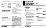
Programming the RS232 Interface
Step 1 Determine zone type and
number
Fill in the table below before beginning to
program your RadioTouchTM RS232 Interface.
The example shows the information to be
recorded in the table.
0
Zone
No.
Zone
Description
Zone
Type
LED Display
Readout
1
2
3
4
5
6
7
8
9
= Unassigned
= Lights
= Sivoia
TM
shades
= Contact closure
–
L
S
C
Room Location:
0
Zone
No.
Zone
Description
Zone
Type
LED Display
Readout
1
2
3
4
= Unassigned
= Lights
= Sivoia
TM
shades
= Contact closure
–
L
S
C
Room Location:
Example:
NOTE: Leave the completed table below with
the building or A/V maintenance group. This
information is important in system
troubleshooting and reprogramming.

9
Section 2 - Start-Up
RadioTouchTM Setup Guide for RTA-RS232
Programming the RS232 Interface
Step 2 Configuring zone types
Step A:Enter unit configuration mode by pressing and
holding the mode and address buttons for 5
seconds. The LED display will begin flashing
UC when the unit has entered unit
configuration mode.
Step B:Once UC is flashing, press the mode button
repeatedly until the display shows CC.
Once the display shows CC press the enter
button to begin configuring zone types.
See the RTA-RS232 Setup Guide for interface
programming and operation instructions. For
additional system details consult the
RadioTouch
TM
Installers Guide, which is
included with each RadioTouch
TM
Controller.
RadioTouch is a trademark of Lutron Electronics Co., Inc.
This product may be covered by one or more of the following
U.S. patents: 5,248,919; 5,399,940; 5,736,965; 5,798,581;
5,838,226; 5,848,054; 5,905,442, 5,982,103
For additional assistance call the Lutron Technical
Support Center at
(800) 523-9466.
OR
Optional Terminal
Block Connector
12
3
Common
Data In
Data Out
P/N 500-9258 Rev A
• Continued on next page.

10
Section 2 - Start-Up
RadioTouchTM Setup Guide for RTA-RS232
Step 2 Continued
Step C:Using the left scroll button, select the zone
number which you would like to configure.
See the RTA-RS232 Setup Guide for interface
programming and operation instructions. For
additional system details consult the
RadioTouch
TM
Installers Guide, which is
included with each RadioTouch
TM
Controller.
RadioTouch is a trademark of Lutron Electronics Co., Inc.
This product may be covered by one or more of the following
U.S. patents: 5,248,919; 5,399,940; 5,736,965; 5,798,581;
5,838,226; 5,848,054; 5,905,442, 5,982,103
For additional assistance call the Lutron Technical
Support Center at
(800) 523-9466.
OR
Optional Terminal
Block Connector
12
3
Common
Data In
Data Out
P/N 500-9258 Rev A
Once the appropriate zone number is
displayed on the left LED display, use the
right scroll button to select the correct zone
type. [Lights (L), Shades (S), Closures (C), and
Unassigned (-).]
Once the correct zone number and type are
displayed, press the enter button to confirm
that this is the setting you require. The 3 LEDs
will flash to signal the change has been made.
See the RTA-RS232 Setup Guide for interface
programming and operation instructions. For
additional system details consult the
RadioTouch
TM
Installers Guide, which is
included with each RadioTouch
TM
Controller.
RadioTouch is a trademark of Lutron Electronics Co., Inc.
This product may be covered by one or more of the following
U.S. patents: 5,248,919; 5,399,940; 5,736,965; 5,798,581;
5,838,226; 5,848,054; 5,905,442, 5,982,103
For additional assistance call the Lutron Technical
Support Center at
(800) 523-9466.
OR
Optional Terminal
Block Connector
12
3
Common
Data In
Data Out
P/N 500-9258 Rev A
Step D:To configure more zones, go back to Step C
and start again.
Step E: Press the mode button to perform another
setup step or press and hold the address and
mode buttons for approximately 5 seconds to
exit unit configuration mode.
See the RTA-RS232 Setup Guide for interface
programming and operation instructions. For
additional system details consult the
RadioTouch
TM
Installers Guide, which is
included with each RadioTouch
TM
Controller.
RadioTouch is a trademark of Lutron Electronics Co., Inc.
This product may be covered by one or more of the following
U.S. patents: 5,248,919; 5,399,940; 5,736,965; 5,798,581;
5,838,226; 5,848,054; 5,905,442, 5,982,103
For additional assistance call the Lutron Technical
Support Center at
(800) 523-9466.
OR
Optional Terminal
Block Connector
12
3
Common
Data In
Data Out
P/N 500-9258 Rev A
Programming the RS232 Interface

11
Section 2 - Start-Up
RadioTouchTM Setup Guide for RTA-RS232
Step A:Enter unit configuration mode by pressing and
holding the address and mode buttons for 5
seconds. The LED display will begin flashing
UC when the unit has entered unit
configuration mode.
Step B:Once UC is flashing, press the mode button
repeatedly until the display shows AS.
Once the display shows AS press the enter
button to begin addressing zones.
See the RTA-RS232 Setup Guide for interface
programming and operation instructions. For
additional system details consult the
RadioTouch
TM
Installers Guide, which is
included with each RadioTouch
TM
Controller.
RadioTouch is a trademark of Lutron Electronics Co., Inc.
This product may be covered by one or more of the following
U.S. patents: 5,248,919; 5,399,940; 5,736,965; 5,798,581;
5,838,226; 5,848,054; 5,905,442, 5,982,103
For additional assistance call the Lutron Technical
Support Center at
(800) 523-9466.
OR
Optional Terminal
Block Connector
12
3
Common
Data In
Data Out
P/N 500-9258 Rev A
Step 3 Adding a zone on the RS232
Interface to a RadioTouchTM
Controller
• Continued on next page.
Programming the RS232 Interface

12
Section 2 - Start-Up
RadioTouchTM Setup Guide for RTA-RS232
Step 3 Continued
Step C:Press the left scroll button repeatedly until
the zone number you wish to address is
displayed.
See the RTA-RS232 Setup Guide for interface
programming and operation instructions. For
additional system details consult the
RadioTouch
TM
Installers Guide, which is
included with each RadioTouch
TM
Controller.
RadioTouch is a trademark of Lutron Electronics Co., Inc.
This product may be covered by one or more of the following
U.S. patents: 5,248,919; 5,399,940; 5,736,965; 5,798,581;
5,838,226; 5,848,054; 5,905,442, 5,982,103
For additional assistance call the Lutron Technical
Support Center at
(800) 523-9466.
OR
Optional Terminal
Block Connector
12
3
Common
Data In
Data Out
P/N 500-9258 Rev A
Then press the address button and the
display will show P with the zone number to be
programmed and the address LED will turn on.
Step D:Go to the RadioTouchTM Controller you wish to
add to the RS232 Interface zone. Press and
release the programming button on the
Controller. After the button is pressed the
lights will cycle up and down for 3 seconds to
notify you that you are in programming mode,
and settle at 50% light output. If you are using
an RTA-RX-SW the lights will cycle OFF and
ON. The Status LED on the Controller will be
in
fast blink
mode. If no lights are connected to
this Controller, the status LED will be your only
feedback.
1234 5678
CLASS 2 LOW VOLTAGE WIRING
Burn-In
12
345678
Occ. Common
Signal
15V
24V
Circuit Com
0-10 Purple
0-10-Gray
Class 2 wiring connections shown above.
Occ. Sensor
0-10 V
12345
Power
Status Program
RadioTouchTM Controller
Programming the RS232 Interface

13
Section 2 - Start-Up
RadioTouchTM Setup Guide for RTA-RS232
Step H:To address additional zones on the RS232
Interface, press the address button and
return to Step C. To exit configuration mode,
press and hold the mode and address
buttons until the display starts to sequence
(approximately 5 seconds).
See the RTA-RS232 Setup Guide for interface
programming and operation instructions. For
additional system details consult the
RadioTouch
TM
Installers Guide, which is
included with each RadioTouch
TM
Controller.
RadioTouch is a trademark of Lutron Electronics Co., Inc.
This product may be covered by one or more of the following
U.S. patents: 5,248,919; 5,399,940; 5,736,965; 5,798,581;
5,838,226; 5,848,054; 5,905,442, 5,982,103
For additional assistance call the Lutron Technical
Support Center at
(800) 523-9466.
OR
Optional Terminal
Block Connector
12
3
Common
Data In
Data Out
P/N 500-9258 Rev A
Step F: On the Controller, press the program button
again to exit from program mode. The lights
will go to high end and the Status LED will
return to
slow blink
mode. If you are using an
RTA-RX-SW the lights will cycle OFF and ON.
Step E: While in programming mode press and hold
the left scroll* and enter buttons on the
RS232 Interface for 5 seconds. When the
Controller has added the RS232 zone, the
lights will flash or cycle OFF and ON. If no
lights are connected to this Controller, hold the
buttons until the 3 LEDs around the display
flash (approximately 5 seconds).
Step G:Repeat steps D – F for any other Controllers
that should be controlled by this zone of the
RS232 Interface.
1234 5678
CLASS 2 LOW VOLTAGE WIRING
Burn-In
12
345678
Occ. Common
Signal
15V
24V
Circuit Com
0-10 Purple
0-10-Gray
Class 2 wiring connections shown above.
Occ. Sensor
0-10 V
12345
Power
Status Program
RadioTouchTM Controller
See the RTA-RS232 Setup Guide for interface
programming and operation instructions. For
additional system details consult the
RadioTouch
TM
Installers Guide, which is
included with each RadioTouch
TM
Controller.
RadioTouch is a trademark of Lutron Electronics Co., Inc.
This product may be covered by one or more of the following
U.S. patents: 5,248,919; 5,399,940; 5,736,965; 5,798,581;
5,838,226; 5,848,054; 5,905,442, 5,982,103
For additional assistance call the Lutron Technical
Support Center at
(800) 523-9466.
OR
Optional Terminal
Block Connector
12
3
Common
Data In
Data Out
P/N 500-9258 Rev A
• Continued on next page.
Programming the RS232 Interface
* Note: To add a zone to an RTA-RS232 Interface
shipped before August 2002 (date code K31) press
and hold the right scroll and enter buttons on the
RS232 Interface for 5 seconds when performing Step
E.

14
Section 2 - Start-Up
RadioTouchTM Setup Guide for RTA-RS232
Step A:Enter unit configuration mode by pressing and
holding the mode and address buttons for 5
seconds. The LED display will begin flashing
UC when the unit has entered unit
configuration mode.
Step B:Once UC is flashing, press the mode button
repeatedly until the display shows HS.
Once the display shows HS press the enter
button and the current flow control setting will
be displayed on the right LED display.
See the RTA-RS232 Setup Guide for interface
programming and operation instructions. For
additional system details consult the
RadioTouch
TM
Installers Guide, which is
included with each RadioTouch
TM
Controller.
RadioTouch is a trademark of Lutron Electronics Co., Inc.
This product may be covered by one or more of the following
U.S. patents: 5,248,919; 5,399,940; 5,736,965; 5,798,581;
5,838,226; 5,848,054; 5,905,442, 5,982,103
For additional assistance call the Lutron Technical
Support Center at
(800) 523-9466.
OR
Optional Terminal
Block Connector
12
3
Common
Data In
Data Out
P/N 500-9258 Rev A
Step 4 Set data flow control method
No flow control is the default for the RS232 Interface. If
you are using no flow control, you have completed the
Start-Up of the RS232 Interface. If you are using full
seven wire hardware handshaking or three wire
software flow control, continue with Step 4.
Programming the RS232 Interface

15
Section 2 - Start-Up
RadioTouchTM Setup Guide for RTA-RS232
Step C:Press the right scroll button to select
between S (software flow control), H (hardware
handshaking), and – (no flow control).
See the RTA-RS232 Setup Guide for interface
programming and operation instructions. For
additional system details consult the
RadioTouch
TM
Installers Guide, which is
included with each RadioTouch
TM
Controller.
RadioTouch is a trademark of Lutron Electronics Co., Inc.
This product may be covered by one or more of the following
U.S. patents: 5,248,919; 5,399,940; 5,736,965; 5,798,581;
5,838,226; 5,848,054; 5,905,442, 5,982,103
For additional assistance call the Lutron Technical
Support Center at
(800) 523-9466.
OR
Optional Terminal
Block Connector
12
3
Common
Data In
Data Out
P/N 500-9258 Rev A
Once the correct letter is displayed, press the
enter button to confirm that this is the setting
you require. The 3 LEDs around the display
will flash to signal the change has been made.
Step D:Press the mode button to perform another
setup step. To exit configuration mode, press
and hold the mode and address buttons until
the display starts to sequence (approximately
5 seconds).
Programming the RS232 Interface
Note: Pressing the left scroll button will
display the current configuration for this mode.
See the RTA-RS232 Setup Guide for interface
programming and operation instructions. For
additional system details consult the
RadioTouch
TM
Installers Guide, which is
included with each RadioTouch
TM
Controller.
RadioTouch is a trademark of Lutron Electronics Co., Inc.
This product may be covered by one or more of the following
U.S. patents: 5,248,919; 5,399,940; 5,736,965; 5,798,581;
5,838,226; 5,848,054; 5,905,442, 5,982,103
For additional assistance call the Lutron Technical
Support Center at
(800) 523-9466.
OR
Optional Terminal
Block Connector
12
3
Common
Data In
Data Out
P/N 500-9258 Rev A

16
Section 3 - Protocol
RadioTouchTM Setup Guide for RTA-RS232
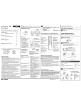
9
Female DB9 Pinout for
RS232 Interface
54321
876
Purpose
This document describes the commands available to control a RadioTouchTM system via the RadioTouchTM RS232
Interface, Model Number RTA-RS232.
Communication Settings
To configure your device to talk to the RadioTouchTM RTA-RS232 Interface, use the data conventions listed
below.
9600 BAUD
8 Data Bits
1 Stop Bit
No Parity
For definition purposes, the host is considered the Data Terminal Equipment (DTE) and the RTA-RS232 is
considered the Data Communications Equipment (DCE).
Typical Interface Wiring
The RTA-RS232 is designed to accept a standard 9 pin serial cable to interface to the host. The RTA-RS232 also
includes an adapter that allows terminal block connections to the RTA-RS232. This adapter is for use in Software
Flow Control only. The following table describes each connection scheme.
Notes on Protocol
Pin Name
DCD
RX
TX
DTR
GND
DSR
RTS
CTS
RI
Pin Description
Data Carrier Detect (not used)
Host Data In/RTA-RS232 Data Out
Host Data Out/RTA-RS232 Data In
Data Terminal Ready
Ground / Common
Data Set Ready
Request To Send
Clear To Send
Ring Indicator (not used)
DB-9 Serial
Cable Pin
Connection
1
2
3
4
5
6
7
8
9
RTA-RS232
Terminal Block
Connection
3
2
1
Common
Data In
Data Out
Terminal Block Connections
for RS232 Interface
123

17
Section 3 - Protocol
RadioTouchTM Setup Guide for RTA-RS232
Zones
A zone is an accessory, or group of accessories, such as lights or Sivoia® Motorized Shades, controlled
simultaneously as a single unit. The RadioTouch
TM RS232 Interface can control up to 10 zones, numbered 0
through 9. Each zone can be configured as lights, Sivoia
® Motorized Shades, or Contact Closures.
Functions
The following functions are available through the RTA-RS232.
Setting Lighting Zone Levels
Lighting zone level refers to the intensity of the light. The zone may be set to an explicit level, a preset level, or
raised/lowered. The explicit levels include a continuous range, or a specific level. See page 21 for a complete
description of each explicit level.
For a continuous range, a value of 0 indicates off; whereas, a value between 1 and 100 represents intensity, in
percent, between low end and high end.
There are a total of 16 presets available. Preset light intensities are stored in the RF Controller. When an RF
Controller receives a Preset command, it adjusts its light intensity to the value stored in the Preset.
When the RTA-RS232 receives a command to raise or lower the zone intensity, it commands the intended zone
to raise (lower) it’s intensity for 5 seconds, or until it receives the ESTP (End Step) command.
Light zones will not accept a level of ALLUP or ALLDOWN. Commands for these types of levels will result in an
error.
Controlling Sivoia® Motorized Shades
Sivoia® Motorized Shade level refers to the position of the shades. The zone may be sent to a preset level or
raised/lowered. Sivoia® Motorized Shades zones may only accept Presets 1-4, ALLUP, or ALLDOWN. The raise/
lower operation behaves the same as that of a Lights zone, however, the timeout period is 150 seconds, instead
of 5 seconds.
Controlling Contact Closures
Contact Closure zones only respond to preset levels. Any other type of level will result in an error. When a contact
closure zone receives a preset command, it will activate the switch closure associated with that preset for 250
milliseconds. If the preset number is greater than 5, it will ignore the data and send an error message if the unit is
in Reply Back Mode.
Setting Presets
The preset light level for a lighting zone may be set via the RTA-RS232. In order to do this, however, DIP Switch 1
on the RF Controller in the intended zone must be in the down position or the zone must have received the enter
Preset Adjust Mode from the RS232 Interface or one of the transmitters in the room. Once this is done, any or all
the presets for that zone may be set. Once the presets are set, the DIP Switch on the RF Controller must be
placed in the up position or the exit Preset Adjust Mode command must be sent.
System Configuration
General
When setting the RTA-RS232 configurations, the host must first enter Configuration Mode. After completing the
configurations, the host must then exit Configuration Mode. If the system is in Configuration Mode, the only
commands that the RTA-RS232 will execute are Configuration commands. All other commands will be ignored.
Conversely, if the RTA-RS232 is not in Configuration Mode, it will ignore Configuration Commands.
Zones
Zones may be configured as one and only one of the following: Lights, Sivoia® Motorized Shades, Contact
Closures, or Unassigned. There are a total of 10 zones available on the RadioTouchTM RS232 Interface,
numbered 0-9. These zones may be configured either by software control over the data link, or manually using the
programming buttons on the RTA-RS232 unit. The default zone configuration is Unassigned.
Notes on Protocol

18
Section 3 - Protocol
RadioTouchTM Setup Guide for RTA-RS232
Reply Back
The RTA-RS232 has the ability to reply to the host whether it processed the last command successfully or not.
This mode can be turned on or off. If Reply Back is turned on, and the RTA-RS232 successfully processes a
command, the RTA-RS232 will respond to the host with:
~OK<CR>
In addition, if the RTA-RS232 is in Configuration Mode and Reply Back Mode is on, the RTA-RS232 will echo
back the last command upon successful completion. For instance, if Zone 1 is to be configured as lights; the
following data is transferred
Host :CON,TYPE,1,L<CR>
RTA-RS232 ~CON,RPT,TYPE,1,L<CR>
If the command is not successfully processed by the RTA-RS232, it will respond to the host with:
~ERROR,
error number
<CR>
See Error Codes on page 26 for a list of error numbers and error descriptions. The default setting for Reply Back
Mode is ON.
Acknowledge
The RTA-RS232 has the ability to inform the host when it has completed RF transmission of an RS232 command.
This mode can be turned on or off. After completing RF transmission, the RTA-RS232 will respond to the host
with:
~ACK<CR>
The default setting for Acknowledge Mode is OFF.
ADD/DELETE RTA-RS232
Each utilized zone of the RTA-RS232 needs to be addressed to the RF Controller(s) it is intended to control. See
the RadioTouchTM Installer’s Guide, part number 031-200, for information on addressing.
Data Flow Control
The RTA-RS232 Interface can only accept one command at a time. When it is done processing this command, it
will inform the host it is ready to receive more data. The method by which it informs the host depends whether it is
using Hardware Handshaking, Software Flow Control or No Flow Control.
Hardware Handshaking
The RadioTouchTM RS232 interface supports full hardware handshaking. In this mode, the system utilizes TX, RX,
CTS, RTS, DTR, DSR, and Ground.
Software Flow Control
If hardware handshaking is not being used, care must be taken to ensure all messages are captured. Once the
Host issues a command, it cannot issue another one until the RTA-RS232 issues a prompt “!” (ASCII 33d).
No Flow Control
In No Flow Control Mode the RTA-RS232 will not provide any indication that it is able to receive more data from
the host. In order to prevent messages from being lost, the host must ensure that each message transmitted to
the RTA-RS232 is separated by at least 400ms. No Flow Control is the default setting.
Notes on Protocol

19
Section 3 - Protocol
RadioTouchTM Setup Guide for RTA-RS232
Command Set
General Command Structure
All commands are sent as ASCII characters. Numerical data fields are the ASCII representation of the decimal
value.
There should be no spaces between characters. Each command has a prefix, a limited number of fields, and an
end character. All commands from the Host device will have a prefix of a colon, :, and an end character of a
carriage return, <CR>. All responses from the RTA-RS232, except for the prompt, will have a prefix of a tilde, ~,
and end with a carriage return, <CR>. Each field is separated by a comma.
Command Format :Command,[Parameters],{Extended Parameters}<CR>
: Indicates start of command
, Field Separator
Command Command as shown
Parameters Zone number or other parameters relevant to the command
Extended Parameters Parameters that do not apply to all variations of a particular command
<CR> Carriage Return, ASCII character 13d – indicates end of command
If your equipment does not support the transmission of ASCII characters, you will need to convert the messages
from ASCII to whatever form your equipment supports, i.e. hexadecimal. For example, to command the
RadioTouch
TM RS-232 Interface to set zone one to preset one, the ASCII text command :PS,1,1<CR> is issued:
ASCII : P S , 1 , 1 <CR>
Hexadecimal 3A 50 53 2C 31 2C 31 0D
Notes on Protocol

20
Section 3 - Protocol
RadioTouchTM Setup Guide for RTA-RS232
Command Summary
RTA-RS232 Commands
Command Description
ENTER This command informs the RTA-RS232 to enter Configuration Mode
EXIT This command informs the RTA-RS232 to exit Configuration Mode
TYPE This command sets the zone type to Lights, Sivoia® Motorized Shades, Contact
Closures, or Unassigned
RB This informs the RTA-RS232 to turn Reply Back Mode ON or OFF
ACK This command turns Acknowledgment Mode ON or OFF
ADD This command adds the RTA-RS232 to an RF controller
DELETE This command deletes the RTA-RS232 from an RF controller
RPT This command allows the host to inquire about the configuration settings of the
RTA-RS232 unit
Page
26
26
26
26
27
27
27
27
Command Description
PS This command will set the indicated zone to a specific preset level
XC This command sets the intended zone to a specific level between the maximum and
minimum levels
BSTP This command informs the RTA-RS232 to RAISE or LOWER the level for the
indicated zone
ESTP This command informs the RTA-RS232 to cease raising or lowering the zone
SPS This command will program the indicated preset level to the current light level
PSA This command informs the indicated zone to enter/exit Preset Adjust Mode
PING This command is used to force a prompt from the RTA-RS232. It is useful upon
power up to kick start data flow
PHC This command informs the indicated zone to enter/exit Photosensor Calibration
Mode
Configuration Commands
Page
21
23
24
24
25
24
24
25
Command Description
! This response from the RTA-RS232 informs the Host that there is room left in its
buffer to accept another command
CON The configuration reports inform the host of the current configuration settings
ERROR With Reply Back Mode ON, the RTA-RS232 will provide error codes when an error
is detected
OK With Reply Back Mode ON, the RTA-RS232 responds with OK when a command is
successfully processed
ACK The RTA-RS232 issues this when it has completed RF transmission of its current
command
RTA-RS232 Responses
Page
28
28
28
29
29
/