Page is loading ...

1
016-0171-664 Rev. F 6/2019 E33023
Copyright 2019
CRX Operation
Guide

016-0171-686 Rev. A, E31924
We Solve Great Challenges.
DISCLAIMER
While every effort has been made to ensure the accuracy of this
document, Raven Industries assumes no responsibility for
omissions and errors. Nor is any liability assumed for damages
resulting from the use of information contained herein.
Raven Industries shall not be responsible or liable for incidental or
consequential damages or a loss of anticipated benefits or profits,
work stoppage or loss, or impairment of data arising out of the
use, or inability to use, this system or any of its components. Raven
Industries shall not be held responsible for any modifications or
repairs made outside our facilities, nor damages resulting from
inadequate maintenance of this system.
As with all wireless and satellite signals, several factors may affect
the availability and accuracy of wireless and satellite navigation
and correction services (e.g. GPS, GNSS, SBAS, etc.). Therefore,
Raven Industries cannot guarantee the accuracy, integrity,
continuity, or availability of these services and cannot guarantee
the ability to use Raven systems, or products used as components
of systems, which rely upon the reception of these signals or
availability of these services. Raven Industries accepts no
responsibility for the use of any of these signals or services for
other than the stated purpose.

1
CONTENTS
Contents . . . . . . . . . . . . . . . . . . . . . . . . . . . . . . . . . . . . . . . . . . . . . . . . . . . . . . 1
Manual Overview. . . . . . . . . . . . . . . . . . . . . . . . . . . . . . . . . . . . . . . . . . . . . . . . 3
Important Safety Information . . . . . . . . . . . . . . . . . . . . . . . . . . . . . . . . . . . . . . 3
CR7 and CR12 Overview . . . . . . . . . . . . . . . . . . . . . . . . . . . . . . . . . . . . . . . . . 3
Care and Maintenance . . . . . . . . . . . . . . . . . . . . . . . . . . . . . . . . . . . . . . . . . . 7
Installation . . . . . . . . . . . . . . . . . . . . . . . . . . . . . . . . . . . . . . . . . . . . . . . . . . . . . 8
Initial Set Up . . . . . . . . . . . . . . . . . . . . . . . . . . . . . . . . . . . . . . . . . . . . . . . . . . . 8
Quick Start Machine Configuration . . . . . . . . . . . . . . . . . . . . . . . . . . . . . . . . 11
Detailed Machine Configuration. . . . . . . . . . . . . . . . . . . . . . . . . . . . . . . . . . . 11
Home Screen Overview . . . . . . . . . . . . . . . . . . . . . . . . . . . . . . . . . . . . . . . . . 12
CRX Settings Menu. . . . . . . . . . . . . . . . . . . . . . . . . . . . . . . . . . . . . . . . . . . . . 15
Overview and Shortcuts. . . . . . . . . . . . . . . . . . . . . . . . . . . . . . . . . . . . . . . . . 15
Machine Configuration. . . . . . . . . . . . . . . . . . . . . . . . . . . . . . . . . . . . . . . . . . 18
Grower, Farm, Field (GFF) . . . . . . . . . . . . . . . . . . . . . . . . . . . . . . . . . . . . . . . 22
Create a New GFF. . . . . . . . . . . . . . . . . . . . . . . . . . . . . . . . . . . . . . . . . . . . . 22
Edit GFF . . . . . . . . . . . . . . . . . . . . . . . . . . . . . . . . . . . . . . . . . . . . . . . . . . . . 23
Delete GFF . . . . . . . . . . . . . . . . . . . . . . . . . . . . . . . . . . . . . . . . . . . . . . . . . . 23
Start a Job . . . . . . . . . . . . . . . . . . . . . . . . . . . . . . . . . . . . . . . . . . . . . . . . . . . . 24
Start or Resume a Job. . . . . . . . . . . . . . . . . . . . . . . . . . . . . . . . . . . . . . . . . . 24
Start a New Job in a New field. . . . . . . . . . . . . . . . . . . . . . . . . . . . . . . . . . . . 25
Operation Planning. . . . . . . . . . . . . . . . . . . . . . . . . . . . . . . . . . . . . . . . . . . . . 26
Pre-Planning . . . . . . . . . . . . . . . . . . . . . . . . . . . . . . . . . . . . . . . . . . . . . . . . . 27
Planning. . . . . . . . . . . . . . . . . . . . . . . . . . . . . . . . . . . . . . . . . . . . . . . . . . . . . 29
Run Screen Overview . . . . . . . . . . . . . . . . . . . . . . . . . . . . . . . . . . . . . . . . . . . 32
Run Screen Overview . . . . . . . . . . . . . . . . . . . . . . . . . . . . . . . . . . . . . . . . . . 32
Widgets . . . . . . . . . . . . . . . . . . . . . . . . . . . . . . . . . . . . . . . . . . . . . . . . . . . . . 34
WIDGET OPTIONS . . . . . . . . . . . . . . . . . . . . . . . . . . . . . . . . . . . . . . . . . . . . 36
Switchbox Operation . . . . . . . . . . . . . . . . . . . . . . . . . . . . . . . . . . . . . . . . . . . 36
Scout Objects . . . . . . . . . . . . . . . . . . . . . . . . . . . . . . . . . . . . . . . . . . . . . . . . . 37
Creating a Flag . . . . . . . . . . . . . . . . . . . . . . . . . . . . . . . . . . . . . . . . . . . . . . . 37
Create a Field Boundary, Do Not Apply Zone, or Application Zone . . . . . . . 38
Create Guidance Lines . . . . . . . . . . . . . . . . . . . . . . . . . . . . . . . . . . . . . . . . . . 40
Adjust Section Control . . . . . . . . . . . . . . . . . . . . . . . . . . . . . . . . . . . . . . . . . . 42
Adjust Rate Control Settings . . . . . . . . . . . . . . . . . . . . . . . . . . . . . . . . . . . . . 43
CRX Settings Menu. . . . . . . . . . . . . . . . . . . . . . . . . . . . . . . . . . . . . . . . . . . . . 43
Display . . . . . . . . . . . . . . . . . . . . . . . . . . . . . . . . . . . . . . . . . . . . . . . . . . . . . . 43
Localization . . . . . . . . . . . . . . . . . . . . . . . . . . . . . . . . . . . . . . . . . . . . . . . . . . 44
Serial Port . . . . . . . . . . . . . . . . . . . . . . . . . . . . . . . . . . . . . . . . . . . . . . . . . . . 44
GPS . . . . . . . . . . . . . . . . . . . . . . . . . . . . . . . . . . . . . . . . . . . . . . . . . . . . . . . . 45
Remote Support. . . . . . . . . . . . . . . . . . . . . . . . . . . . . . . . . . . . . . . . . . . . . . . 46
Master Switch Configuration . . . . . . . . . . . . . . . . . . . . . . . . . . . . . . . . . . . . . 47
ISOBus Settings . . . . . . . . . . . . . . . . . . . . . . . . . . . . . . . . . . . . . . . . . . . . . . 47
Lightbar . . . . . . . . . . . . . . . . . . . . . . . . . . . . . . . . . . . . . . . . . . . . . . . . . . . . . 48
Notifications . . . . . . . . . . . . . . . . . . . . . . . . . . . . . . . . . . . . . . . . . . . . . . . . . . 48

2
Wi-FI Configuration. . . . . . . . . . . . . . . . . . . . . . . . . . . . . . . . . . . . . . . . . . . . . 49
Manual Network Creation . . . . . . . . . . . . . . . . . . . . . . . . . . . . . . . . . . . . . . . 50
Creating a Personal Hotspot . . . . . . . . . . . . . . . . . . . . . . . . . . . . . . . . . . . . . 50
Screen Capture . . . . . . . . . . . . . . . . . . . . . . . . . . . . . . . . . . . . . . . . . . . . . . . . 50
Using Screen Capture Tool . . . . . . . . . . . . . . . . . . . . . . . . . . . . . . . . . . . . . . 50
Using the Power Button . . . . . . . . . . . . . . . . . . . . . . . . . . . . . . . . . . . . . . . . . 51
Exporting Screen shots . . . . . . . . . . . . . . . . . . . . . . . . . . . . . . . . . . . . . . . . . 51
Viewing Screen shots . . . . . . . . . . . . . . . . . . . . . . . . . . . . . . . . . . . . . . . . . . 51
File Manager . . . . . . . . . . . . . . . . . . . . . . . . . . . . . . . . . . . . . . . . . . . . . . . . . . 52
File Types . . . . . . . . . . . . . . . . . . . . . . . . . . . . . . . . . . . . . . . . . . . . . . . . . . . 52
Copy a File. . . . . . . . . . . . . . . . . . . . . . . . . . . . . . . . . . . . . . . . . . . . . . . . . . . 53
Delete a File. . . . . . . . . . . . . . . . . . . . . . . . . . . . . . . . . . . . . . . . . . . . . . . . . . 53
Import Maps, Guidance Lines, and Feature Unlocks. . . . . . . . . . . . . . . . . . . 54
Load A Prescription Map . . . . . . . . . . . . . . . . . . . . . . . . . . . . . . . . . . . . . . . . 56
Eject the USB . . . . . . . . . . . . . . . . . . . . . . . . . . . . . . . . . . . . . . . . . . . . . . . . 58
Software and Hardware Updates. . . . . . . . . . . . . . . . . . . . . . . . . . . . . . . . . . 59
Software. . . . . . . . . . . . . . . . . . . . . . . . . . . . . . . . . . . . . . . . . . . . . . . . . . . . . 59
Downloading a CRX Update to USB . . . . . . . . . . . . . . . . . . . . . . . . . . . . . . . 60
Install CRX Updates via USB . . . . . . . . . . . . . . . . . . . . . . . . . . . . . . . . . . . . 60
ISO Node and GPS Updates . . . . . . . . . . . . . . . . . . . . . . . . . . . . . . . . . . . . . 61
SmarTrax System Information . . . . . . . . . . . . . . . . . . . . . . . . . . . . . . . . . . . . 62
Implement Steering System Information . . . . . . . . . . . . . . . . . . . . . . . . . . . . 62
Feature Unlocks . . . . . . . . . . . . . . . . . . . . . . . . . . . . . . . . . . . . . . . . . . . . . . . 62
Temporary Unlock . . . . . . . . . . . . . . . . . . . . . . . . . . . . . . . . . . . . . . . . . . . . . 63
Permanent Unlock . . . . . . . . . . . . . . . . . . . . . . . . . . . . . . . . . . . . . . . . . . . . . 64
System Shutdown. . . . . . . . . . . . . . . . . . . . . . . . . . . . . . . . . . . . . . . . . . . . . . 65
USB Import and Export File Types . . . . . . . . . . . . . . . . . . . . . . . . . . . . . . . . 66

3
MANUAL OVERVIEW
This manual is designed for use with CRX software version 2.4. Updates for Raven
manuals are available at the Applied Technology Division web site:
http://portal.ravenprecision.com/
Sign up for e-mail alerts to receive notifications when Raven products updates are
available on the Raven website.
IMPORTANT SAFETY INFORMATION
This is a safety-alert symbol. When you see this symbol on the
field computer, be alert because there is the potential for
personal injury.
Follow the recommended precautions and safe operating
practices.
CR7 AND CR12 OVERVIEW
Both the CR7 and CR12 field computers feature a dust-proof design (IP65); bright,
easy-to-use touchscreen interface; and ISO Universal Terminal (UT) and Task
Controller (TC) capabilities making these field computers a flexible plug-and-play
option for building an affordable system.
Both the CR7 and CR12 utilize the CRX operating software platform featuring easy
job set-up; customizable in-job layouts; and an intuitive tablet-style interface. These
field computers are also compatible with many Raven systems including:
• SmarTrax™ or SmarTrax MD™ automated steering control.
• Slingshot Online Services.
• Raven ISO Products such as Hawkeye
®
and Raven Rate Control Module (RCM).
• Raven ISO AutoBoom™ boom height management.
•Raven AccuBoom™.
• Raven SCS 400, 600, 4400, and 4600 series consoles.
NOTE: Contact a local Raven dealer for information on additional features and
options available for use with the CR7 and CR12 field computers

4
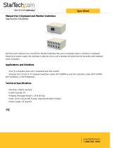
The CR7™ is a 7” lightweight field computer with a simplified widget concept.
FIGURE 1. CR7 Field Computer
Touch
Screen
Integrated
Light Bar
Ethernet
Port
1” RAM
Mount
I/O Cable
Connection
Power
Button
USB Port
Power and
GPS
Connection

5
The CR12 is a larger version of the CR7 with a 12.1” capacitive touch screen, and an
intuitive, tablet-style interface. Both the CR7 and CR12 consoles feature:
•Dustproof design
• Anti-reflective though screen for optimal visibility
• Clear and easy to use
•Integrated Wi-Fi module for easy remote support
FIGURE 2. CR12 Field Computer
Touch
Screen
Ethernet
Port
2” RAM
Mount
Main Interface
Connector
Power
Button
USB Port
(x2)
Power
Connection
Video Output/
External Display
AUX CANbus
Video Input
(Not Used)

6
SPECIFICATIONS
CR7 CR12
Connections
• 2 ISOBUS Channels
• 3 Serial Channels
• 1 USB 2.0 Port
• 1 Gigabit Ethernet Port
• 1 Wi-Fi 802.11 b/g/n
• Bluetooth 2.1 with EDR and
BLE 4.0
• 1 Radar Speed Output
• 2 Digital Sense Inputs
• 2 USB 2.0 ports
• 4 ISOBUS 2.0 Compatible
Ports
• 5 RS232 Series Data Ports
(GPS Out, GPS In, Console,
Auxiliary, RTK)
Display
• 7” Widescreen
• Capacitive Touch
• 480 x 800 Resolution
• Screen Brightness 850 NITS
• Integrated Lightbar
• 12” Widescreen
• Capacitive Touch
• 1024 x 768 Resolution
• Screen Brightness 850 NITS
Computing
• 8 GB Storage
•1 GB RAM
• 852 MHz Quad Core
Processor
• 30 GB Internal Storage
•1 GB RAM
•Quad Core Cortex A9
Processor
Power
• 7 to 16 VDC Input
• 850 mA Typical
• Supply Power Fuse: 5 Amp
MINI
®
Fuse
• Keyed Power Start-Up and
Shut-Down
• 4 to 35 VDC Input
Mechanical
• 7.5” x 5.6” x 3.0”
(19 cm x 14.25 cm x 7.62 cm)
• Weight: 1.4 lbs (0.64 kg)
• 1” RAM Ball Mount
• 9.63” x 12.02” x 1.79”
(24.46 cm x 30.53 cm x 4.55
cm)
• Weight: 4.7 lbs (2.13 kg)
•2” RAM Ball Mount
Environmental
• Operating Temperature
Range: -20°C to 70°C
• Storage Temperature Range:
-40°C to 70°C
• IP65 Moisture Protection
• Operating Altitude: 2000m
Maximum
• Operating Temperature
Range: -20°C to 70°C
• Storage Temperature Range:
-40°C to 85°C
• IP65 Moisture Protection

7
CARE AND MAINTENANCE
• Harsh chemicals may damage the touch screen. Clean the touch screen and
exterior as needed with a soft cloth dampened with glass cleaner. Apply the
cleaner to the cloth and then wipe the screen gently.
• Removing power from the field computer without shutting down may result in
damage to the unit which will require the field computer to be returned for
service.
• To avoid scratching the touch screen, do not use any type of sharp instrument.
• Store the field computer in a dry environment when not in use.
• Damage to the field computer may occur if the USB ports are used to charge
mobile devices such as cellular phones, tablets, or mp3 devices. USB ports should
only be used for performing file transfer and maintenance.
• Route cables to prevent tripping hazards and to keep wires from pinching or
breaking.
• When temperatures are expected to be 10° F (-12° C) or lower, remove the field
computer from the vehicle and store it in a climate controlled environment.
• Even when powered down, the field computer will draw a small amount of power
from the vehicle battery. If the machine will not be in operation for an extended
period of time (e.g. more than a couple weeks), disconnect the power cable from
the back of the field computer.
Certifications
•CE
•E-Mark
•CE
At Raven Industries, we strive to make your experience with our products
as rewarding as possible. One way to improve this experience is to provide
us with feedback on this manual. Your feedback will help shape the future
of our product documentation and the overall service we provide. We
appreciate the opportunity to see ourselves as our customers see us and
are eager to gather ideas on how we have been helping or how we can do
better. To serve you best, please send an email with the following
information to
-CRX™ Operation Guide
-Manual No. 016-0171-664 Rev. F
-Any comments or feedback (include chapter or page numbers if
applicable).
-Let us know how long have you been using this or other Raven products.
We will not share your email or any information you provide with anyone
else. Your feedback is valued and extremely important to us.

8
INSTALLATION
1. Mount the antenna on the centerline of the tallest point of the vehicle (usually on
the top of the vehicle cabin) using the magnetic mount. Make sure that the
antenna has a clear, 360° view of the sky. If the mounting location is non-
magnetic, use a mounting plate to mount the antenna.
2. Route the Power/GPS cable to the back of the field computer and connect it to
the Power/GPS port.
3. Use the provided RAM mount arm to install the field computer inside the cab.
4. For additional cabling and connection assistance, refer to the CR7 and CR12
Installation Guide. Additional system diagrams are available on the Raven
website.
http://portal.ravenprecision.com/
INITIAL SET UP
When starting the system for the first time, a setup wizard will walk you through a
setup process and, if desired, allow you to quickly begin creating guidance lines. This
section covers the first time startup.
IMPORTANT: Check all measurements before entering values into the field computer and
enter all measurements as accurately as possible. Check that values entered
on the field computer are consistent with measurements.
IMPORTANT: The CR12 startup wizard will ask for the cable harness type used with the field
computer. The default option is 115-8000-064 and should only be used if the
part number of the cable harness connected to the CRX field computer
matches. If using a different cable, select ”Other” from the drop-down. If
needed, the cable selection can be edited later in the GPS Information tab.

9
After powering up the system for the first time:
1. Select the desired language from the drop-down on the First Run Setup: Select
Language screen.
FIGURE 3. Select Language
NOTE: Screen layout and button/widget location may vary slightly from the
images shown in this manual.
2. Press Next . The First Run Setup: Select Time Zone screen will be displayed.
NOTE: At any time press Previous to return to the previous screen.
3. Select the desired time zone from the drop-down.
NOTE: Time zones are based on an offset from Coordinated Universal Time
(UTC). Ex. Los Angeles is UTC-08:00, New York is UTC-05:00, Berlin is
UTC+01:00, and Moscow is UTC+03:00. It may be necessary to add an
extra hour for daylight savings time for some regions.
4. Press Next . The First Run Setup: Select Units screen will be displayed.
5. Select the desired units (US Standard, Metric, or Turf) for each of the
measurement types (Distance, Speed, Area, Weight, Volume, Pressure, and
Temp erat ure ).

10
FIGURE 4. Select Units
6. Press Next . Either the First Run Setup: Simplified User Interface or the First
Run Setup:Grower/Farm screen will display. Skip to step 9 when configuring a
CR12.
7. CR7 offers a Simplified User Interface option which provides a basic set of
guidance focused features and options.
Do not enable this feature if the field computer will be used to control product
application or planting operations, if detailed application maps and reports will
be needed for multiple operations, if it will be connected to an ISO or CANbus
system, or detailed file maintenance is necessary for field operation reporting.
8. Press Next . The First Run Setup: Grower/Farm screen will display.
9. Enter the desired grower name in the Name the Default Grower field.
10. Press Next . The First Run Setup: Configure Machine Configuration screen will
be displayed.
NOTE: A Machine Configuration allows the user to select the type of
equipment used for various field operations (e.g. tractor and
implement, self-propelled sprayer, etc.) and quickly switch between
configurations when using the CRX system with various machines or
types of towed implements.
11. Select the Quick Start option to set up a basic machine configuration
or select the Create Detailed Machine Configuration option to set up
a more detailed machine configuration such as a tractor with a towed implement.
NOTE: Selecting the Quick Start provides simple set up to complete the initial
configuration and begin using the CRX system. Both configuration
options may be edited later as needed.

11
QUICK START MACHINE CONFIGURATION
NOTE: The Quick Start option only allows the operator to create basic
guidance lines. For additional functionality, select the Create Detailed
Machine Configuration option during the initial set up.
1. Select Quick Start . The Machine Configuration: Quick Start window
will be displayed.
2. Enter the desired Guidance Width in feet (meters).
NOTE: The Guidance Width is the width of the implement and that will be
“painted” to display previous area covered during a field operation. This
measurement is used for creating swath widths for guidance lines and is
crucial for most field applications.
3. Press Accept . The End User License Agreement prompt will be displayed.
4. Review the information in the End User License Agreement and select OK. The
Warning prompt will be displayed.
5. Read and acknowledge the information on the Warning window. The Home
screen (see Figure 5 on page 12) will be displayed and the CRX system is ready for
in-field operations.
NOTE: Press the Settings button at any time it is visible to return to the
Settings screen.
DETAILED MACHINE CONFIGURATION
A detailed machine configuration allows the user to enter detailed machine and
implement measurements for optimized guidance for specific equipment types (e.g.
self-propelled sprayer versus towed planter behind an articulated tractor) and
additional guidance features.
Refer to the Machine Configuration section on page 18 for additional information
regarding setting up detailed machine configurations.

12
HOME SCREEN OVERVIEW
The Home screen (see Figure 5 on page 12) provides a basic location display, access
to system and machine settings, and options for starting New Jobs.
FIGURE 5. Home Screen
NOTE: Go to portal.ravenslingshot.com to locate and download Street Maps
for use with CRX.
•Review Initial Set Up section on page 8 for additional assistance with system setup.
•Refer to Start a Job section on page 24 for assistance with starting a job.
•See Run Screen Overview section on page 32 for additional information on using
tools and features during an in-field operation.
STATUS BAR
The status bar provides a quick reference for status of the CRX system and
connected devices. Note that some status icons use different icon colors to indicate a
different status.
TABLE 1. Status Bar Icons
Icon Name Description
Bluetooth
Connected
Indicates that there is a Bluetooth device
connected to the CRX.
GPS No Data
GPS is not detected. For assistance with GPS
issues, refer to the GPS section on page 45.
Status Bar
Left
Side
Bar
Right
Side
Bar
Footer Bar

13
GPS Bad
No GPS. For assistance with GPS issues, refer
to the GPS section on page 45.
GPS Warning
Poor GPS signal. To address GPS issues, refer
to the GPS section on page 45.
GPS Ideal GPS is active and receiving a good signal.
Slingshot Disabled
Slingshot is not available. Refer to the
Slingshot operation manual for additional
information on Slingshot functionality.
Slingshot
Connected
Slingshot is connected. Refer to the Slingshot
operation manual for additional information
on Slingshot functionality.
Slingshot Transfer
Slingshot is currently transferring data. Refer
to the Slingshot operation manual for
additional information on Slingshot
functionality.
Signal Strength
Strength of wireless signal. Refer to the
Slingshot operation manual for additional
information on Slingshot functionality.
Remote Support
Disabled
Remote support session is not active. Refer to
the “Remote Support” on page 46 for
additional information on remote support.
Remote Support
Active
Remote support session active.
SmarTrax Disabled
SmarTrax is turned off. If desired, press one of
the SmarTrax resume switches on the machine
to turn SmarTrax back on. Refer to the
SmarTrax operation manual for additional
information on SmarTrax operation.
SmarTrax Not
Ready
SmarTrax is not ready to be engaged. Refer to
the SmarTrax operation manual for additional
information on SmarTrax operation.
SmarTrax Ready
SmarTrax is ready to operate. Refer to the
SmarTrax operation manual for additional
information on SmarTrax operation.
SmarTrax Node
Download
SmarTrax node update is being installed. Refer
to the SmarTrax operation manual for
additional information on SmarTrax operation.

14
FOOTER TOOLS
The buttons at the bottom of the screen provide easy access to settings and features
such as the UT, any active alarms or notifications, and also different views for use
during an in-field operation. Review the following descriptions of the function of the
icons displayed in the footer.
TABLE 2. CRX Footer Tools
Software Update
A CRX software update is available. Refer to
“Software and Hardware Updates” on page 59
for additional information on performing a
CRX software update.
USB Scanning
Indicates that CRX is scanning the connected
USB drive. Refer to “Software and Hardware
Updates” on page 59 for additional
information on updates.
USB Transfer
CRX is transferring files from the connected
USB drive.
Outdoor Sensor Outdoor Sensor is communicating.
Icon Name Description
Toggle View
Toggle between the 3D and aerial view during
in-field operations.
Alarms
Display information about active alerts or
review notification history.
Confirm
Select confirm to either accept the change or
exit the job.
Cancel
Select Cancel to stop performing the current
selection.
Screen Capture
Press this to capture a screen shot of the
current screen.
Create Job in a
New Field
Select this icon to start a new job in a new
field.
Settings Menu Open the Settings Menu.
UT
Select UT to open and control components on
the ISOBUS.

15
CRX SETTINGS MENU
OVERVIEW AND SHORTCUTS
FIGURE 6. Settings Menu
The following settings and options are available via the various menu screens.
NOTE: Menu options may appear over multiple screens. Swipe to the left or
right to view additional menus.
TABLE 3. Settings Screens
Icon Information
Add menu options to the Shortcut Bar for quick access to
frequently used settings and features.
Base Stations allows for the creation and configuration of local base
stations.
The display can be set to Day or Night Mode and the Screen and
Lightbar Brightness can be adjusted in the Display screen.
Allows users to import/export files as well as view and delete files.
Customizable
Shortcut Bar

16
Create, Rename, or Delete Growers, Farms, or Fields.
Review GPS information, diagnostics, and adjust settings.
Provides settings for Path Deviation Sensitivity, Center settings, and
Reverse LED Indication.
Provides setting options for Language, Time Zone, and Units of
Measure.
Networking allows for the creation and configuration of Wi-Fi and
other network connections.
Allows the user to add a new machine or to update the existing
machine configuration.
Provides options that can be used as the input for master switch
status of connected nodes. If no other options are selected, select
the On-Screen option to record coverage.
Select this page to adjust prescription map Look Ahead settings for
Variable Rate Applications (VRA).
Select this page if working with technical support and they request
access to the CRX via Slingshot. Click Enable Remote Support to
allow them access to the CRX.
Provides control for individual settings including the On Override,
Turn Off Percentage, and Look Ahead settings for section control.
Configures the units for use with product control of the console.
Typically these match the units configured within the SCS console.
Icon Information

17
ADD SHORTCUTS
To add a widget to the Shortcut Bar:
1. Touch Add Shortcut in the Customizable Shortcut Bar.
2. Select the desired setting menu.
Provides information on the serial connection speed and the type
of serial device.
Slingshot is a subscription based service that allows the user to
transfer files remotely. Slingshot also allows the service desk to
perform remote service on the system.
Allows the user to adjust On Line (OL) Sensitivity and the Line
Acquire speed, configure all SmarTrax settings and run SmarTrax
calibration.
If there is a software update available, it can be installed on this
page using either Slingshot Link or a USB drive. GPS and CRX
unlock status and System information can also be found on this
page.
Provides information on UT instances, identify UT’s or clear UT
object pools.
Select volume to adjust notification volume levels.
The weather sensor provides support for add on components that
measure temperature, humidity, etc. The information from the
weather station can be recorded along with other job information.
Icon Information

18
REMOVE OR CHANGE SHORTCUTS
To remove or change an icon in the Customizable Shortcut Bar:
1. Touch and hold the desired menu option for 2 seconds. An “X” will be displayed
in the top, left corner of the selected menu item.
2. Touch the X to remove the menu item or select a different menu item from the
Settings Menu options.
MACHINE CONFIGURATION
IMPORTANT: Entering all measurements as accurately as possible will ensure the best
coverage and guidance results during in-field operations. Verify all
measurements before entering them into CRX and check values entered for
each setting or option.
Perform machine configuration when installing the CRX system on a new machine.
To configure a machine:
1. On the settings screen, press the Machine button. The machine
Configuration window will open.
2. Press the Add Machine button . The Select Machine window will open.
3. Press Create New Machine.
4. Select the machine type. Available options are:
• Traditional
• Self Propelled
•Articulated
•Tracked
NOTE: During machine configuration, if creating a self-propelled machine with
an ISO boom connected to the CANBUS, select the ISO Boom instead of
creating a new boom.
NOTE: During machine configuration, if selecting a SCS, select the desired SCS
instead of creating a new boom.
5. Enter the machine name in the <enter name> field.
6. Press Next . The Antenna Height Above Ground window will open.
7. Enter the Height from the ground to the center of the antenna.
/