Page is loading ...

User Guide
DESKTOP PHONE SYSTEM
TS-user manual 7th ED v3 Release.qxd 8/27/02 4:56 PM Page i

Copyright Information
Centrepoint Technologies Inc, Copyright 2002. All Rights Reserved.
Reproduction, adaptation or translation without prior written permission is
prohibited, except as allowed under the copyright laws.
Information in this user guide is subject to change without notice and does not
represent any commitment on the part of Centrepoint Technologies Inc.. No part of
this user guide may be reproduced or transmitted in any form or by any means,
electronic or mechanical, including photocopying, recording, or information storage
and retrieval systems, or translated to another language, for any purpose other than
the licensee’s personal use and, as specifically allowed in the licensing agreement,
without the express written permission of Centrepoint Technologies Inc..
Seventh Edition, August 2002.
Printed in Canada
TS-user manual 7th ED v3 Release.qxd 8/27/02 4:56 PM Page ii

Table of Contents
1.0 Installing TalkSwitch
1.1 What's included with TalkSwitch ................................1
1.2 Front Panel Descriptions ...................................2
1.3 Back Panel Descriptions ...................................3
1.3.1 The TalkSwitch 24 .................................3
1.3.2 The TalkSwitch 48 .................................4
1.4 Plugging into the Back Panel ..................................6
1.4.1 Attaching telephone lines to TalkSwitch line jacks ...........6
1.4.2 Attaching phones and other analog devices
to TalkSwitch extension jacks ......................6
1.4.3 Connecting Devices to the Music and PA Jacks .............7
1.4.4 Connecting TalkSwitch to a PC ........................8
1.4.4.1 Serial connection ........................8
1.4.4.2 USB connection .........................9
1.4.4.3 LAN connection ........................10
1.4.4.4 Remote configuration using a modem .........10
1.4.4.5 Local configuration using a modem ...........12
1.5 Using 2 or more TalkSwitch units on a LAN ........................12
1.5.1 Connecting 2 or more TalkSwitch units to a LAN ...........12
1.5.2 Setting the Unit ID for the first time .....................15
1.5.3 Changing the Unit ID ..............................15
1.5.4 Unit IDs and how they affect the system extension numbers ....15
1.5.5 Keeping track of the lines and extensions ................16
1.5.6 Optimizing the system for networked use ................16
2.0 Configuring TalkSwitch
2.1 Installing the TalkSwitch Configuration Software ....................19
2.2 Control Center ..................................20
2.3 Configuration ..................................21
2.3.1 System Information ...............................26
2.3.1.1 Telephone Lines ........................26
2.3.1.2 Line Hunt Groups .......................28
2.3.1.3 Fax Information ........................29
2.3.1.4 Local Extensions ........................30
2.3.1.5 Remote Extensions ......................32
2.3.1.6 Extension Ring Groups ...................34
2.3.1.7 Music-on-hold .........................36
TS-user manual 7th ED v3 Release.qxd 8/27/02 4:56 PM Page iii

2.3.2 Voicemail ..................................37
2.3.2.1 Local Extension Voicemail .................37
2.3.2.2 Remote Extension Voicemail ................38
2.3.2.3 General Voicemail .......................40
2.3.2.4 Global Settings ........................41
2.3.3 Call Handling ..................................43
2.3.3.1 Modes ..............................43
2.3.3.2 Auto Attendant .........................44
2.3.3.3 Telephone Lines ........................49
2.3.3.4 Local Extensions - Call Cascade .............51
2.3.3.5 Remote Extensions - Call Cascade ...........54
2.3.3.6 Extension Ring Groups - Call Cascade .........56
2.3.4 Call Back / Call Bridge ............................57
2.3.4.1 Auto Call Back .........................59
2.3.4.2 Prompted Call Back .....................61
2.3.4.3CallBridge ...........................64
2.3.5 Options ..................................65
2.3.5.1 Administrator Password ...................65
2.3.5.2 Audio Controls .........................66
2.3.5.3 Manual Transfer ........................67
2.3.5.4 Miscellaneous .........................68
2.3.5.5 Troubleshooting ........................71
3.0 Using TalkSwitch
3.1 In the Office - Receiving calls with or without the Auto Attendant ........75
3.1.1 Receiving calls using the Auto Attendant ................75
3.1.2 Receiving calls without the Auto Attendant ...............76
3.2 In the Office - Making and Receiving Calls .......................76
3.2.1 Making calls from a Local Extension ...................76
3.2.2 Receiving calls at a Local Extension ....................76
3.2.3 Placing calls on Hold at a Local Extension ...............77
3.2.4 Transferring calls ................................77
3.2.5 Call Park - Parking and retrieving callers ................78
3.2.6 Call Queue - Queuing and retrieving callers .............79
3.2.7 Conference calling with TalkSwitch ....................80
3.2.8 Using Phones connected in parallel to TalkSwitch ..........81
3.2.9 External modem telephone line access ..................82
3.3 Out of the Office - Receiving Calls through Call Forwarding ...........83
3.3.1 The three ways to forward calls .......................83
3.3.2 Screening options for forwarded calls ..................84
TS-user manual 7th ED v3 Release.qxd 8/27/02 4:56 PM Page iv

3.4 Using the TalkSwitch Voicemail System ..........................85
3.4.1 Activating Voice mailboxes ..........................85
3.4.2 Accessing a Voice mailbox ..........................86
3.5 Music-on-Hold ..................................87
3.6 Mode Switching Options ..................................89
3.7 Out of the Office - Making Calls with Call Back and Call Bridge ........89
3.7.1 Using Call Bridge ................................89
3.7.2 Using Call Back .................................91
3.8 Upgrading the TalkSwitch Firmware ............................92
Appendices
Appendix A - Help & Troubleshooting ..............................99
Appendix B - Using TalkSwitch with Telephone Company Calling Services ....109
Appendix C - Quick Commands and DTMF Functions .................113
Appendix D - Safety Precautions and Regulatory Information .............117
AppendixE-TalkSwitch One Year Warranty .........................121
AppendixF-Return Policy .................................125
Appendix G - Specifications ................................127
AppendixH-TalkSwitch and Power Interruptions .....................129
Glossary .......................................................131
Index .......................................................139
TS-user manual 7th ED v3 Release.qxd 8/27/02 4:56 PM Page v

1.1 What's included with TalkSwitch
The TalkSwitch products come shipped with the following items.
1. The TalkSwitch Unit
2. AC Power Adapter (Warning: never use any other Power Adapter other than
the one provided with the TalkSwitch.)
3. 9 pin Serial Cable
4. 6' RJ-11 Telephone Cable - (2)
5. Software CD (This contains the configuration software and manual)
6. Quick Reference Cards - (Local Extension Use)
7. TalkSwitch Memory Card (optional purchase for TalkSwitch 48 models)
If any of these items are missing, please contact your reseller.
The TalkSwitch Line jacks are sensitive to high voltage spikes from lightning. If you live
in an area where electrical storms occur regularly, we recommend that you protect
TalkSwitch by plugging the telephone cords coming from the TalkSwitch line jacks to a
surge protection device connected to the incoming telephone lines.
When you first receive TalkSwitch and live in an area with cold temperatures, do not
plug TalkSwitch into a power outlet until the system has warmed to room temperature.
Otherwise condensation could build up on the electronics and cause damage when
powered up.
1
11.0 Installing TalkSwitch
Installing
TalkSwitch
TS-user manual 7th ED v3 Release.qxd 8/27/02 4:56 PM Page 1

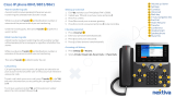
1.2 Front Panel Descriptions
TalkSwitch's front panel consists of a power button ("Power") and 5 LED lights that
do more than let you know TalkSwitch is plugged in and turned on.
What do the LED lights tell you?
LED light: State Description
Line 1 On Solid Line 1 is currently in use.
Pulsing Slowly The Line 1 caller is on hold.
Flickering Line 1 is ringing.
Quick Pulse Line 1 is engaged by another device on the line.
Line 2 On Solid Line 2 is currently in use.
Pulsing Slowly The Line 2 caller is on hold.
Flickering Line 2 is ringing.
Quick Pulse Line 2 is engaged by another device on the line.
Power / Data On Solid TalkSwitch is powered on.
Flickering The PC connected (via Serial or USB) to
TalkSwitch is either sending or retrieving
information from TalkSwitch.
Pulsing Slowly Global Message Waiting Indicator (optional).
Line 3
*
On Solid Line 3 is currently in use.
Pulsing Slowly The Line 3 caller is on hold.
Flickering Line 3 is ringing.
Quick Pulse Line 3 is engaged by another device on the line.
Line 4
*
On Solid Line 4 is currently in use.
Pulsing Slowly The Line 4 caller is on hold.
Flickering Line 4 is ringing.
Quick Pulse Line 4 is engaged by another device on the line.
*
Line 3 and 4 lights apply to TalkSwitch 48 models
2 TalkSwitch User Manual
TS-user manual 7th ED v3 Release.qxd 8/27/02 4:56 PM Page 2

1.3 Back Panel Descriptions
Before connecting all your phones and lines to TalkSwitch, you may want to
proceed with configuring the unit first. (See section 2.1) This will minimize the
disruption time for your telephone lines while setting up the system.
1.3.1 The TalkSwitch 24
Jacks/Ports What to plug in
MUSIC Plug in a radio, CD player, PC soundcard or any other
device that emits an audio signal if you wish to use
TalkSwitch's Music-on-Hold feature. This is a 1/8" (3.5
mm) phono jack. Mono cables are recommended.
PA Connect to a P.A. system if you wish to use the external
paging feature. This is a 1/8" (3.5 mm) phono jack.
Mono cables are recommended.
E1, E2, E3, E4 Plug in any analog device that uses a standard (RJ-11)
telephone jack, such as: telephones, answering
machines, fax machines, internal or external PC
modems. Once these devices are plugged in TalkSwitch
will recognize them as Ext. 111, Ext. 112, Ext. 113, or
Ext. 114. Consider connecting the receptionist’s phone to
Extension 114 as this will allow for calls to be received or
made through Line 1 of TalkSwitch.
L1/L2, L2 This is where you plug in your telephone lines (RJ-11).
If you have 2 lines out of 1 phone jack, you can plug into
the L1/L2 jack. Use a surge protector if you live in an
area prone to lightning strikes.
USB Use the USB port if your PC supports USB connectivity. If
you use the USB port, you cannot use the serial port
simultaneously. Windows 2000/XP currently not
supported for USB connectivity.
31.0 Installing TalkSwitch
TS-user manual 7th ED v3 Release.qxd 8/27/02 4:56 PM Page 3

SERIAL Attach the supplied serial cable (RS232) that connects
TalkSwitch to your PC. If you use the serial port you
cannot use the USB port simultaneously.
POWER Plug the supplied AC Power Adapter in here. Rating:
16VAC 1.1 A output. Do not use any other power adapter
as this may cause damage.
By default, TalkSwitch is set to Serial connection. To activate USB connection, dial
91 from an extension then reset TalkSwitch. To return to Serial connection, dial
90 and reset TalkSwitch.
The ‘PF’ box in between E4 and L1/L2 represents power failure support. In the event
of a power failure or loss of power to TalkSwitch, Extension 114 will be able to receive
calls and make calls on Line 1.
1.3.2 The TalkSwitch 48
JJ
JJ
aa
aa
cc
cc
kk
kk
ss
ss
//
//
PP
PP
oo
oo
rr
rr
tt
tt
ss
ss
WW
WW
hh
hh
aa
aa
tt
tt
tt
tt
oo
oo
pp
pp
ll
ll
uu
uu
gg
gg
ii
ii
nn
nn
MUSIC Plug in a radio, CD player, PC soundcard or any other
device that emits an audio signal if you wish to use
TalkSwitch's Music-on-Hold feature. This is a 1/8" (3.5
mm) phono jack. Mono cables are recommended. If you
have multiple TalkSwitch units on a LAN, you will need
to provide a music source to each TalkSwitch.
PA Connect to a P.A. system if you wish to use the external
paging feature. This is a 1/8" (3.5 mm) phono jack.
Mono cables are recommended. If you have multiple
TalkSwitch units on a LAN, you will need to provide a
connection from each TalkSwitch to the PA Amplifier.
4 TalkSwitch User Manual
LAN
MEMORY SLOT
USB SERIAL POWER
MUSIC
L1
/
L
2
L2
PA
E1
E2
E3
E4
PF
L3/L4
L4
E5
E6
E7 E8
TS-user manual 7th ED v3 Release.qxd 8/27/02 4:56 PM Page 4

LAN PORT You can connect to an Ethernet hub using a Category 5
cable with RJ-45 connectors. This will support
configuration across the LAN. If you have 2 or more
TalkSwitch 48 units, you can ‘network’ them and they
will function as a single system. There are 3 LEDs next
to the LAN port. The top LED is on when a link has been
established with any TalkSwitch or PC running
TalkSwitch software. The 2nd LED is on when data is
being received and the 3rd LED is on when data is being
transmitted.
E1 - E8 Plug in any analog device that uses a standard (RJ-11)
telephone jack, such as: telephones, fax machines,
internal or external PC modems, etc. TalkSwitch identi-
fies the extensions as 1x1 to 1x8. (x represents the unit
ID number assigned to that TalkSwitch unit). By default
all TalkSwitch units are shipped with a unit ID = 1. This
means the extensions are 111 to 118. If it had unit ID 2
then they would be 121 to 128. For details on setting up
2 or more units on a LAN to operate as ‘networked’
units, please see section 1.5.
L1/L2, L2, L3/L4, L4 This is where you plug in your telephone lines (RJ-11).
If you have 2 lines out of 1 phone jack, you can plug into
the 1/2 and 3/4 jacks. Use a surge protector if you live
in an area prone to lightning strikes.
USB Use the USB port if your PC supports USB connectivity. If
you use the USB port, you cannot use the serial port
simultaneously. Windows 2000/XP currently not
supported for USB connectivity.
SERIAL Attach the supplied serial cable (RS232) to connect
TalkSwitch to your PC.
MEMORY SLOT Memory expansion slot. Used to expand internal
memory for voicemail and Auto Attendant messages.
TalkSwitch Memory cards can be purchased from your
local TalkSwitch reseller. Simply place the memory card
in the slot and TalkSwitch will automatically detect and
start using the extra memory within 20 seconds.
POWER Plug the supplied AC Power Adapter in here. Rating:
16VAC 1.1 A output. Do not use any other power adapter
as this may cause damage.
51.0 Installing TalkSwitch
TS-user manual 7th ED v3 Release.qxd 8/27/02 4:56 PM Page 5

By default, TalkSwitch is set to Serial connection. To activate USB connection, dial
91 from an extension then reset TalkSwitch. To return to Serial connection, dial
90 and reset TalkSwitch. No commands are required to use the LAN connection.
The ‘PF’ box in between E4 and L1/L2 represents power failure support. In the event of
a power failure or loss of power to TalkSwitch, Extension 114 will be able to receive calls
and make calls on Line 1.
1.4 Plugging into the Back Panel
1.4.1 Attaching telephone lines to TalkSwitch line jacks
You can connect your telephone lines from the wall jack(s) to the TalkSwitch Line
jacks with the phone cables provided. Take note of which telephone line is connected
to which Tel Line number - this information will be used in the configuration section.
In order to minimize disruption to your business, you may want to configure
TalkSwitch first before connecting it to your lines and phones.
TalkSwitch works with many telephone company services such as 3-Way Calling and
Distinctive Ring. For more information on phone company services, see Appendix B.
1.4.2 Attaching phones and other devices to TalkSwitch extension
jacks
You can connect any analog device (regular telephone, cordless phone, fax machine,
answering machine, modem) to TalkSwitch's extension jacks. Multiple devices can be
connected to each extension jack by 'chaining' them together or using a line splitter.
To Attach a Single Line Corded or Cordless Telephone, Fax Machine or Answering
Machine:
Connect your single line analog telephone or fax machine to one of TalkSwitch's
extension jacks (E1 to E4 for the TalkSwitch 24 and E1 to E8 for the TalkSwitch
48) just as you would if you were plugging them into a standard telephone wall
jack.
To Attach a Two-line Telephone:
Option # 1 (Use it as one TalkSwitch extension.)
Disregard the telephone's Line 2 jack (plug-in). Connect the telephone's Line 1
plug-in to any one of TalkSwitch's extension jacks. You will still be able to access
both telephone lines in the same manner as if you were using a single line
telephone attached to TalkSwitch.
6 TalkSwitch User Manual
TS-user manual 7th ED v3 Release.qxd 8/27/02 4:56 PM Page 6

Option # 2 (Use it as two TalkSwitch extensions.)
You could use your two-line telephone as two separate TalkSwitch extensions.
Connect the telephone's Line 1 and Line 2 plug-ins to two separate extension
jacks.
Most two-line phones have separate plug-ins for two incoming telephone lines (Line 1
and Line 2). If your two-line telephone does not have separate plug-ins, you can use
a "Line 1/Line 2" line splitter to separate the two lines. Download the Quick Guide at
www.talkswitch.com for more detailed examples on connecting multi-line phones.
To Attach an Internal or External Modem:
Simply plug the modem's telephone cable into one of TalkSwitch's extension
jacks. Your modem is now a TalkSwitch extension and will be able to access all
lines and take advantage of TalkSwitch's call routing features.
If you would like to use a telephone on the same extension as your modem,
simply plug the telephone's cable into the modem's telephone jack. (Most
modems have a telephone jack, located beside the 'Line In' jack.)
You do not have to attach a PC to TalkSwitch (via the Serial or USB ports) for
your modem to be functional.
If you don’t want to change your dial up settings for the modem, you will need
to enable Direct Line Access for the extension associated to the modem. See
section 2.3.1.4 for more details on configuring Direct Line Access.
1.4.3 Connecting Devices to the Music and PA Jacks
The Music jack is designed to support any audio source (CD player, radio, tape player,
sound card etc.) for playing music or messages to callers while on hold. Simply
connect the audio source via its headphone output to the Music jack. The Music jack
requires a 1/8” (3.5mm) phono connector. If you have more than one TalkSwitch
connected to a LAN, you will need to provide audio to all the Music jacks on each
TalkSwitch.
The PA jack can be connected to a PA System for external paging or to an
amplification system to screen voicemail or to use as a line simulator. The PA jack
requires a 1/8” (3.5mm) phono connector. If you have more than one TalkSwitch
connected to a LAN, you will need to provide a connection from each TalkSwitch to
the PA system.
71.0 Installing TalkSwitch
Networked
TS-user manual 7th ED v3 Release.qxd 8/27/02 4:56 PM Page 7

1.4.4 Connecting TalkSwitch to a PC
There are four ways to connect TalkSwitch directly to your PC for configuration -
Serial, USB (Windows XP, 2000 excluded), Ethernet (LAN port), and remotely using
a dial up modem.
Serial: Use the provided serial cable (RS232) to connect TalkSwitch to an
open COM port on your PC.
USB: Use a USB cable to connect TalkSwitch to an available USB port on
your PC or USB hub.
Ethernet: With the TalkSwitch 48 models, TalkSwitch can be configured using
a PC connected to the same LAN as your TalkSwitch units. TalkSwitch
cannot be configured from the Internet.
Modem: Using a PC with a dial up modem and running the TalkSwitch con-
figuration software, you can choose to call TalkSwitch from anywhere
in the world then connect and configure the system.
1.4.4.1 Connecting TalkSwitch to a PC using a Serial cable
If you have an available Serial port, then connect TalkSwitch to your PC using the
Serial cable provided with TalkSwitch. By default, TalkSwitch is shipped with the
Serial port enabled and the USB port disabled so you do not have to do anything to
get it working using the Serial port.
If you were previously using USB and are switching back to Serial connection, then
you will need to switch TalkSwitch back to Serial mode. Pick up a phone connected
to one of TalkSwitch’s local extensions and dial to enter command mode. If you
have an administrator password enabled, enter the password. Dial 90 then to
enable the Serial connection. Next, turn TalkSwitch off then back on again to
activate the Serial connection..
8 TalkSwitch User Manual
TS-user manual 7th ED v3 Release.qxd 8/27/02 4:56 PM Page 8

When you run the TalkSwitch software, you will need to select ‘PC Connection’ to
select Serial as the connection then select the COM port associated to this physical
Serial port on your PC.
Make sure you do not have any other communications programs running at the
same time you want to use the TalkSwitch configuration software. These may include
Palm Pilot, Hot Sync, TalkWorks, Digital Camera software. These programs tend to
‘hold’ onto COM ports and not make them available for any other programs.
If you are having problems communicating with TalkSwitch, please check the
Troubleshooting section of the manual.
1.4.4.2 Connecting TalkSwitch to a PC using a USB cable
If you have an available USB port and cable and are not running Windows 2000 or
XP on your PC, then connect TalkSwitch to the PC using the USB cable*. Next, pick
up a phone connected to one of TalkSwitch’s local extensions and dial to enter
command mode. If you have an administrator password enabled, enter the password.
Dial 91then to activate the USB connection. Next, turn TalkSwitch off then back
on again to activate the USB drivers.
Make sure you do not have any other communications programs running at the
same time you want to use the TalkSwitch configuration software. These may include
Palm Pilot, Hot Sync, TalkWorks, Digital Camera software. These programs tend to
‘hold’ onto COM ports and not make them available for any other programs.
* USB cable not provided.
91.0 Installing TalkSwitch
TS-user manual 7th ED v3 Release.qxd 8/27/02 4:56 PM Page 9

1.4.4.3 Connecting TalkSwitch to a LAN
If you want to connect multiple TalkSwitch units to a LAN, please see section 1.5
To connect TalkSwitch to a LAN for configuration purposes, simply use a standard
Category 5 cable with RJ45 connectors on either end. Once TalkSwitch is connected
to the hub, the top LED will light only when a computer running the TalkSwitch
software establishes a connection with TalkSwitch. This LED lets you know
TalkSwitch and your PC are able to communicate.
When you run the TalkSwitch software, you will need to select ‘PC Connection’ to
select LAN as the connection then select the LAN adapter on your PC. You do not have
to enter any commands from a local extension on TalkSwitch to enable LAN
connectivity. Make sure you are using TalkSwitch Firmware 1.37 or higher to
configure across the LAN.
If you are running Windows XP, please make sure you are not using Windows 98
compatibility mode. Anytime TalkSwitch is being configured, it is ‘locked’ so that no
other computer or person using a phone can make configuration changes at the
same time. If you leave the software open for longer than 1 hour, TalkSwitch will
automatically unlock itself to allow configuration changes.
1.4.4.4 Connecting to TalkSwitch from a remote location using a modem
TalkSwitch can be configured remotely using any PC with a modem and TalkSwitch
software installed. Version 1.37 or higher of the software and version 2.37 or higher
of the firmware support modem connectivity.
To configure remotely using a modem, you should first ensure that you have at least
version 2.37 of the firmware loaded on TalkSwitch. Next, using the software that
matches the firmware (ie. if the firmware version on TalkSwitch is 2.37, then the
software version should be 1.37) click on ‘PC connection’ after running the software.
Select ‘Remotely using a modem’ for the connection then the associated COM port
for that modem.
10 TalkSwitch User Manual
TS-user manual 7th ED v3 Release.qxd 8/27/02 4:56 PM Page 10

Next, click connect and another screen will appear where you will need to enter the
phone number for one of the lines connected to TalkSwitch. In order for the modem
to establish a connection, an Auto Attendant needs to answer on the line you are
dialing in on. If you do not have an Auto Attendant set to answer on any of the lines,
TalkSwitch will answer with a generic greeting after 15 rings so that you can still get
into the system to access voicemail or make configuration changes.
Once you have entered the phone number, click ‘Connect’. The TalkSwitch software
will now try to communicate with your modem to establish a connection. The
following screen should appear after it has successfully dialed the phone number to
TalkSwitch.
111.0 Installing TalkSwitch
TS-user manual 7th ED v3 Release.qxd 8/27/02 4:56 PM Page 11

1.4.4.5 Connecting to TalkSwitch from a local extension using a modem
TalkSwitch can be configured locally using any PC with a modem connected to
TalkSwitch and has the TalkSwitch software installed. Version 1.37 or higher of the
software and version 2.37 or higher of the firmware support modem connectivity.
Run the TalkSwitch software then click on ‘PC connection’. Select ‘Remotely using a
modem’ for the connection then the associated COM port for that modem.
No phone number is required since the modem is connected to TalkSwitch when the
modem goes ‘off-hook’. The connection should be established very quickly.
1.5 Using 2 or more TalkSwitch units on a LAN
If you have only one TalkSwitch unit, ignore this section and proceed to Section 2.
1.5.1 Connecting 2 or more TalkSwitch units to a LAN
OO
OO
pp
pp
tt
tt
ii
ii
oo
oo
nn
nn
11
11
--
--
CC
CC
oo
oo
nn
nn
nn
nn
ee
ee
cc
cc
tt
tt
tt
tt
oo
oo
ss
ss
ww
ww
ii
ii
tt
tt
cc
cc
hh
hh
oo
oo
rr
rr
ss
ss
ww
ww
ii
ii
tt
tt
cc
cc
hh
hh
ee
ee
dd
dd
hh
hh
uu
uu
bb
bb
ii
ii
nn
nn
cc
cc
oo
oo
ee
ee
xx
xx
ii
ii
ss
ss
tt
tt
ee
ee
nn
nn
cc
cc
ee
ee
ww
ww
ii
ii
tt
tt
hh
hh
yy
yy
oo
oo
uu
uu
rr
rr
PP
PP
CC
CC
ss
ss
..
..
We recommend integrating your phone system into your existing LAN with a switched
hub. A switch or switched hub provides direct communication between TalkSwitch
units, thus keeping the TalkSwitch voice over LAN data isolated from other data on
the network.
Connect up to four TalkSwitch units (2 are shown on the following page) to the LAN
switch or switched hub.
12 TalkSwitch User Manual
Networked
TS-user manual 7th ED v3 Release.qxd 8/27/02 4:56 PM Page 12

Make sure a computer is connected to the phone system either via the LAN or directly
from the computer to the TalkSwitch through the USB or Serial port.
OO
OO
pp
pp
tt
tt
ii
ii
oo
oo
nn
nn
22
22
--
--
CC
CC
oo
oo
nn
nn
nn
nn
ee
ee
cc
cc
tt
tt
tt
tt
oo
oo
rr
rr
ee
ee
gg
gg
uu
uu
ll
ll
aa
aa
rr
rr
hh
hh
uu
uu
bb
bb
dd
dd
ee
ee
dd
dd
ii
ii
cc
cc
aa
aa
tt
tt
ee
ee
dd
dd
tt
tt
oo
oo
TT
TT
aa
aa
ll
ll
kk
kk
SS
SS
ww
ww
ii
ii
tt
tt
cc
cc
hh
hh
uu
uu
nn
nn
ii
ii
tt
tt
ss
ss
If you don't have a switch we suggest you use a small hub on a dedicated LAN to
network the TalkSwitch units. You can connect a computer to this hub for
TalkSwitch configuration purposes, as this hub should not be shared with heavy LAN
traffic.
Connect up to four TalkSwitch units (2 are shown here) to the LAN hub.
Make sure a computer is connected to the phone system either via the LAN or directly
from the computer to the TalkSwitch through the USB or Serial port.
131.0 Installing TalkSwitch
TalkSwitch(unitID1)
TalkSwitch (unit ID 2)
Switch or
Switched Hub
TalkSwitch (unit ID 1)
TalkSwitch (unit ID 2)
Hub
TS-user manual 7th ED v3 Release.qxd 8/27/02 4:56 PM Page 13

OO
OO
pp
pp
tt
tt
ii
ii
oo
oo
nn
nn
33
33
--
--
CC
CC
oo
oo
nn
nn
nn
nn
ee
ee
cc
cc
tt
tt
22
22
uu
uu
nn
nn
ii
ii
tt
tt
ss
ss
tt
tt
oo
oo
gg
gg
ee
ee
tt
tt
hh
hh
ee
ee
rr
rr
vv
vv
ii
ii
aa
aa
aa
aa
nn
nn
EE
EE
tt
tt
hh
hh
ee
ee
rr
rr
nn
nn
ee
ee
tt
tt
cc
cc
rr
rr
oo
oo
ss
ss
ss
ss
--
--
oo
oo
vv
vv
ee
ee
rr
rr
cc
cc
aa
aa
bb
bb
ll
ll
ee
ee
..
..
If you plan to network only two TalkSwitch units, it is possible to network them via a
LAN crossover cable.
Connect the two TalkSwitch units with a crossover cable. Make sure you are using a
crossover cable and not a regular LAN cable - see diagram below for details on how
to verify a crossover cable.
Make sure a computer is connected to the phone system either via the USB or Serial
port.
14 TalkSwitch User Manual
Green
1
2
3
4
5
6
7
8
Blue
Brown
Orange
Orange
1
2
3
4
5
6
7
8
Blue
Brown
Green
Orange
1
2
3
4
5
6
7
8
Blue
Brown
Green
Orange
1
2
3
4
5
6
7
8
Blue
Brown
Green
Straight through cable:
Notice how both ends are identical
Crossover cable:
The ends are different. Pins1&3are
reversed, and pins2&6arereversed.
TalkSwitch (unit ID 1)
TalkSwitch (unit ID 2)
Crossover Cable
TS-user manual 7th ED v3 Release.qxd 8/27/02 4:56 PM Page 14

1.5.2 Setting the Unit ID for the first time
When units are shipped from the manufacturer, they are all programmed with Unit
ID 1. If two or more units are placed on the same LAN and 2 or more have the same
Unit ID number, then there will be a conflict. TalkSwitch identifies this conflict by
flashing all the Line lights on the front panel of the units that have the conflict.
To resolve the conflict, you need to assign a different Unit ID to one or more of the
units. Pick up a telephone handset connected to one of the extension jacks on the
TalkSwitch unit that you want to assign a different Unit ID. You will immediately
hear a system prompt indicating that there is a conflict and a new Unit ID needs to
be chosen. Select an available Unit ID between 2 and 4 (odds are that you are keeping
the Unit ID of the 1st unit set to 1).
Next, the system should indicate that the update was successful and the front panel
lights should stop flashing after several seconds. When none of the front panel ‘Line’
lights are flashing, then all units are ready for network use.
No IP configuring is required since TalkSwitch units do not use the TCP/IP protocol.
TalkSwitch units cannot communicate with any other units beyond the LAN. If you need
to configure remotely, you can use the remote modem option to connect from a remote
location.
1.5.3 Changing the Unit ID
If you need to change the Unit ID of any TalkSwitch system, you can first press
from a Local Extension to enter command mode, enter a password if necessary, then
dial 0 0
.
The system will respond with the Unit ID of that particular TalkSwitch.
To change the Unit ID, use any of the following commands once in command mode:
Unit ID DTMF Command
101
202
303
404
1.5.4 Unit IDs and how they affect system extension numbers
When more than one TalkSwitch is connected to a LAN and they operate in networked
mode, several of the extensions and voicemail have different numbers based on the
Unit ID assigned to the TalkSwitch unit they belong to.
151.0 Installing TalkSwitch
TS-user manual 7th ED v3 Release.qxd 8/27/02 4:56 PM Page 15
/