Page is loading ...

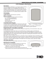
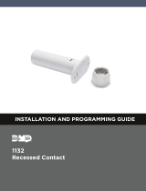
1166 WIRELESS SMOKE RING
Installation Guide
Figure 1: 1166 Wireless
Smoke Ring
DESCRIPTION
Choose one of the smoke alarms in the interconnected system
onto which you will add the 1166.
Since the 1166 does not have a visible Survey LED, use a wireless
device with a Survey LED to confirm that the 1166 will be within
communication range of a DMP wireless receiver or panel. DMP
recommends using an 1106 Wireless Universal Transmitter that has
been programmed into the panel.
Check the Location Using a Survey LED
1. Open the wireless device and hold it over the smoke alarm
onto which the 1166 will be added.
2. Press the tamper switch to send data to the panel and see if
communication is confirmed or faulty.
Confirmed: If communication is confirmed, the Survey
LED blinks immediately on and immediately o for
each press or release of the tamper switch.
Faulty: If communication is faulty, the Survey LED
remains on for up to 8 seconds or flashes multiple
times in quick succession. Chose a dierent smoke
alarm or relocate the wireless receiver until the Survey
LED confirms clear communication.
2
The 1166 Wireless Smoke Ring can
be installed with any traditional
AC-powered interconnected smoke
alarm system.
Traditional smoke alarms only
provide an audible alert in the event
of a fire. The 1166 monitors the
interconnected smoke alarm system
and sends a message to the alarm
panel when any smoke alarm is
triggered.
Only one 1166 is required per smoke
alarm system if all the existing
smoke alarms are interconnected.
Each smoke alarm in a protected
residence must be tested to verify
interconnection prior to installing
1166 devices.
Compatibility
All DMP 1100 Series Wireless
Receivers and burglary panels.
See the last page for compatibility
details. The 1166 has been tested
with the following smoke alarms
by Intertek:
• BRK Brands Model 7010B
• Kidde Model i4618
• First Alert BRK Model 9120B
• Kidde Model i12040
• USI Electric Model 5304
What is Included?
• One 1166 Wireless Smoke Ring
• One 3.0V Lithium CR2477
Battery
• Mounting Screws
PROGRAM THE PANEL
Program the 1166 Wireless Smoke Ring into the panel. Each 1166
programmed takes up one zone in the panel. Refer to the panel
programming guide as needed.
1. In ZONE INFORMATION, enter the ZONE NO: and press
CMD.
2. Enter the ZONE NAME.
3. Select FI (fire) as the ZONE TYPE.
4. At the NEXT ZN? prompt, select NO. If you see the
WIRELESS ZONE prompt, select YES.
5. Enter the eight-digit SERIAL# and press CMD.
6. Enter the SUPRVSN TIME (supervision time) and press
CMD.
7. At the NEXT ZN? prompt, select YES if you are finished
programming the zone. Select NO if you would like to
access additional programming options.
SELECT A SMOKE ALARM
3
1
TEST EXISTING SMOKE ALARMS
Begin by testing for the interconnected status of all the smoke
alarms within the protected area. The 1166 is designed to work
with three-wire AC-powered smoke alarms with an interconnected
wired output. It will not work with two-wire AC-powered smoke
alarms, wireless smoke alarms, or battery powered smoke alarms.
See Compatibility for specific smoke alarm models the 1166 has
been tested with.

2 1166 INSTALLATION GUIDE | DIGITAL MONITORING PRODUCTS
WIRE THE 1166
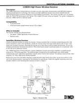
Follow these steps to connect the wires on the 1166 to the smoke alarm pigtail wires. The 1166 only connects
to the white neutral and yellow, orange, or red interconnect wires. The interconnect has a maximum voltage
of 9.0 volts.
Caution: Do not crimp a wiretap onto the hot black wire.
1. Place the 1166’s yellow wiretap over the yellow, orange, or red signal wire and crimp it in place using
pliers. See Figure 3.
2. Place the 1166’s white wiretap over the white neutral wire and crimp it in place using pliers.
3. Fit the wires back into the wiring opening in the smoke alarm mounting base.
4. Reconnect the pigtail connector to the smoke alarm and twist the smoke alarm back into place on its
mounting base.
5. Turn power back on at the breaker to complete the installation.
5
Figure 3: Connecting the
1166’s Wiretaps
White to
White
Once you have confirmed that the 1166 will be within communication range of a receiver or panel, remove the
chosen smoke alarm and install the 1166 mounting base.
1. Turn o power to the smoke alarm system at the breaker before beginning the installation.
2. Remove the chosen smoke alarm from its mounting base by twisting it counterclockwise or clockwise
(depending on the brand).
3. Unplug the pigtail connector and detach the smoke alarm.
4. Remove the screws from the mounting bracket to detach it from the electric junction box.
5. Insert the pigtail wire and wire taps through the center opening in the 1166.
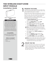
6. Place the 1166 where the mounting base was on the ceiling or wall and then place the mounting base
over the 1166. Line up the screw openings.
7. Use the mounting screws included with the 1166 to attach the mounting base and 1166 to the electric
junction box.
Figure 2: Mounting
Screw Locations
Yellow to
Yellow/Orange/Red
Black
(do not crimp)
REMOVE THE SMOKE ALARM
4

DIGITAL MONITORING PRODUCTS | 1166 INSTALLATION GUIDE 3
TEST THE 1166
After you have installed the 1166, perform the following tests to ensure that the 1166 is successfully sending
messages to the panel. These tests can be performed on any of the system’s smoke alarms.
Press the Test Button
Press the Test button on any of the smoke alarms. If the 1166 is communicating properly, an alarm message on
the 1166’s zone will be transmitted to the panel.
Smoke Testing
1. Use canned smoke or a smoldering punk to direct smoke into the openings of one of the smoke alarms
for 20 seconds or until it goes into alarm.
2. The alarm’s red LED should stay on and the panel should recognize an alarm. Use the system reset
switch to reset the alarm.
Caution: Remember to extinguish the smoke source after testing.
Interconnection Test
Test each smoke alarm and confirm the 1166 activates properly. Ensure the control panel is notified for every
smoke alarm within the protected area.
7
INSTALL OR REPLACE THE BATTERY
6
The 1166 is powered by a 3.0V lithium CR2477 battery inserted into a sliding tray. When the battery gets low, a
LOBAT message is sent to the panel. When the LOBAT message appears on the keypad, replace the battery and
perform a sensor reset by following the process below. For optimum battery life, DMP recommends replacing
the battery with a DMP Model CR2477 or a Sony/Murata CR2477.
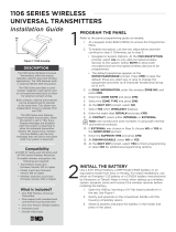
1. Slide open the battery tray on the side of the 1166.
2. Observing polarity, insert a 3.0V lithium CR2477 battery into the battery tray. The positive (+) side of the
battery should face the same direction as the positive (+) mark on the battery tray. See Figure 4.
3. Close the battery tray.
Sensor Reset to Clear LOBAT
Once the battery is replaced, a sensor reset is required at the system keypad to clear the LOBAT message.
1. On a Thinline keypad, press and hold “2” for two seconds. On a touchscreen keypad press RESET.
2. Enter your user code, if required.
3. The keypad displays SENSORS OFF followed by SENSORS ON.
Figure 4: Inserting the Battery
Negative (-)
Side

Designed, engineered, and
manufactured in Springfield, Missouri
using U.S. and global components.
INTRUSION • FIRE • ACCESS • NETWORKS
2500 North Partnership Boulevard
Springfield, Missouri 65803-8877
888-436-7832 | DMP.com
© 2018 Digital Monitoring Products, Inc.
LT-1581 18184 1.01
1166 WIRELESS SMOKE RING
Replacements
CR2477 3.0V Lithium Battery
Certifications
FCC Part 15 Registration ID CCKPC0194
Industry Canada Registration ID 5251A-PC0194
Intertek (ETL) Listed
ANSI/UL 985 Household Fire Warning System
Patents
U. S. Patent No. 7,239,236
Specifications
Battery
Life Expectancy 6 Years (normal
operation)
Type 3.0V Lithium CR2477
Frequency Range 905-924 MHz
Dimensions 6.5” W x 0.5” H
Color White
Housing Material Flame retardant ABS
FCC INFORMATION
This device complies with Part 15 of the FCC Rules. Operation is subject to the following two conditions:
1. This device may not cause harmful interference, and
2. this device must accept any interference received, including interference that may cause undesired operation.
The antenna used for this transmitter must be installed to provide a separation distance of at least 20 cm (7.874 in.) from
all persons. It must not be located or operated in conjunction with any other antenna or transmitter.
Changes or modifications made by the user and not expressly approved by the party responsible for compliance could
void the user’s authority to operate the equipment.
Note: This equipment has been tested and found to comply with the limits for a Class B digital device, pursuant to
part 15 of the FCC Rules. These limits are designed to provide reasonable protection against harmful interference
in a residential installation. This equipment generates, uses and can radiate radio frequency energy and, if not
installed and used in accordance with the instructions, may cause harmful interference to radio communications.
However, there is no guarantee that interference will not occur in a particular installation. If this equipment does
cause harmful interference to radio or television reception, which can be determined by turning the equipment o
and on, the user is encouraged to try to correct the interference by one or more of the following measures:
• Reorient or relocate the receiving antenna.
• Increase the separation between the equipment and receiver.
• Connect the equipment into an outlet on a circuit dierent from that to which the receiver is connected.
• Consult the dealer or an experienced radio/TV technician for help.
INDUSTRY CANADA INFORMATION
This device complies with Industry Canada Licence-exempt RSS standard(s). Operation is subject to the following two
conditions:
1. this device may not cause interference, and
2. this device must accept any interference, including interference that may cause undesired operation of the device.
Le présent appareil est conforme aux CNR d’Industrie Canada applicables aux appareils radio exempts de licence.
L’exploitation est autorisée aux deux conditions suivantes :
1. l’appareil ne doit pas produire de brouillage, et
2. l’utilisateur de l’appareil doit accepter tout brouillage radioélectrique subi, même si le brouillage est susceptible
d’en compromettre le fonctionnement.
The antenna used for this transmitter must be installed to provide a separation distance of at least 20 cm (7.874 in.) from
all persons. It must not be located or operated in conjunction with any other antenna or transmitter.
L’antenne utilisée pour cet émetteur doit être installée de façon à orir une distance de séparation d’au moins 20 cm
(7.874 in.) De toute personne. Il ne doit pas être placé ou utilisé conjointement avec une autre antenne ou un autre
émetteur.
COMPATIBILITY
• 1100X Wireless Receiver Version 104 or higher
• 1100XH Wireless Receiver Version 105 or higher
• 1100D Wireless Receiver Version 104 or higher
• 1100DI Wireless Receiver Version 105 or higher
• 1100DH Wireless Receiver Version 105 or higher
• XT50 Series panels with integrated wireless receiver Version 101 or higher
• XTLplus™ Series panels with integrated wireless receiver
The 1166 has been tested with the following
smoke alarms by Intertek:
• BRK Brands Model 7010B
• Kidde Model i4618
• First Alert BRK Model 9120B
• Kidde Model i12040
• USI Electric Model 5304
/