
MFC 4100 HART
®
Communicator
MFC 4101 HART
Communicator with Documentation
MFC 4102 HART
Communicator with Intrinsic Safety (I.S.)
MFC 4103 HART
Communicator with Documentation and I.S.
OPERATOR
INSTRUCTION MANUAL
File No. 4100:440-4
December 2003

MFC 4100 SERIES OPERATOR INSTRUCTION MANUAL
MFC 4100 HART
®
Communicator
MFC 4101 Communicator with Documenting capability
MFC 4102 Communicator with Intrinsically Safe (I.S.) rating
MFC 4102 Communicator with Documenting capability & I.S. rating
I
MPORTANT
N
OTICE
A
SSISTANCE
For customer assistance please contact the local Meriam Representative or Meriam Process Technologies
directly. For a geographic listing of Representatives and contact information, visit our web site at
www.meriam.com
and click on the “Representatives” button. Contact Meriam Process Technologies
directly by phone at (216) 281-1100 or by e-mail at [email protected]
. Direct all assistance inquiries
to Technical Services.
HART
®
is a registered trademark of the HART Communication Foundation.
Meriam Process Technologies
10920 Madison Avenue
Cleveland, Ohio 44102
TELEPHONE: (216) 281-1100
FAX: (216) 281-0228
E-mail: meriam@meriam.com
Web Site: www.meriam.com
Important information on the product is contained in this
manual. Read this manual carefully and completely before
operating the product. For the safety of the operator and the
system, a thorough understanding of this manual is necessary
before commissioning, using or maintaining the product.

MFC 4100 HART Communicator
OPERATING INSTRUCTIONS
MFC 4100, MFC 4101, MFC 4102, MFT 4103
TABLE OF CONTENTS
Subject Page
MFC 4100 Communicator Overview ........................................................................................................ 1
Display Overview ...................................................................................................................................... 1
Header Line Symbols ........................................................................................................................... 2
Keypad Overview ...................................................................................................................................... 2
Alphanumeric Keys .............................................................................................................................. 3
Left / Right Arrow Keys ....................................................................................................................... 4
Soft Keys............................................................................................................................................... 4
Thumb Operated Keys .......................................................................................................................... 4
General Operation...................................................................................................................................... 5
Power Options....................................................................................................................................... 5
Navigating Menus................................................................................................................................. 5
Turning on MFC ................................................................................................................................... 6
MFC Main Display ............................................................................................................................... 6
MFC Configurations Settings ............................................................................................................... 7
Lockout Feature ............................................................................................................................... 7
Lockout Code.............................................................................................................................. 7
Disable Lockout .......................................................................................................................... 8
Changing Lockout Code ............................................................................................................. 8
Backlight (off timer) ................................................................................................................... 8
Off Timer .................................................................................................................................... 8
Clock Edit ................................................................................................................................... 8
Enter PC Comm. Mode............................................................................................................... 8
Battery Installation & Removal (all models) ............................................................................................. 9
External Connections ................................................................................................................................. 9
DB-9 Connection ....................................................................................................................................... 9
Hazardous Area Use ................................................................................................................................ 10
Intrinsically Safe Operation ................................................................................................................ 10
HART
®
Communications with MFC 4100...............................................................................................11
HART Commands ................................................................................................................................11
HART Connections...............................................................................................................................11
HART Communications .......................................................................................................................12
Initial Screens / Online Mode ......................................................................................................12
Multi-drop Poll.............................................................................................................................13
Manual Device 0 Poll...................................................................................................................13
Offline Menu Mode .....................................................................................................................13
List / Show DOFs....................................................................................................................14
List / Edit Configurations........................................................................................................14
Create Configurations .............................................................................................................15
Delete All Configurations .......................................................................................................15
Delete Individual Configurations / Clearing Configuration Memory.....................................15
Online Setup Mode ......................................................................................................................15
Communications Trouble Shooting .............................................................................................15
More Status Message ...................................................................................................................16

Save / Send Configuration Functions...........................................................................................16
Documenting HART Configurations with Meriam DMS software..........................................................17
MFC 4100 Device Specific & Generic HART Communication ..............................................................17
Using Generic Communications ..........................................................................................................17
DOF / Firmware Download Site ...............................................................................................................18
Who may use.........................................................................................................................................18
PC Requirements ..................................................................................................................................18
Preparing the MFC for updating ...........................................................................................................18
Preparing to Download .........................................................................................................................18
Using the Download Site ......................................................................................................................19
Subscriber Options................................................................................................................................19
MFx Installer Utility .................................................................................................................................19
Returning the MFC for Repairs ................................................................................................................20
APPENDIX
MFC Specifications ..............................................................................................................................21
MFC Models, Options, Ordering Information ......................................................................................21
MFC Accessories List...........................................................................................................................22
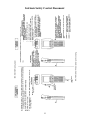
Intrinsically Safe Control Document ....................................................................................................23
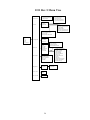
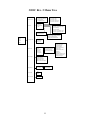
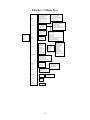
HART Command Structure Menu Trees ........................................................................................ 24-28

1
MFC 4100 HART COMMUNICATOR
The MFC 4100 HART Communicator is the latest handheld communicator in the Meriam family of
HART devices. All HART field devices can be configured, polled, and trimmed using the MFC with
HART communications. The MFC is a full function HART Communicator supporting Universal,
Common Practice and Device Specific commands for commissioning, configuration and maintenance
operations.
Note: For Intrinsically Safe MFC models, consult the
Hazardous Area Use
section of this manual for
specific details on use of approved MFCs and applicable restrictions.
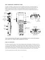
DISPLAY OVERVIEW
The display of the MFC 4100 is a 128 x 128 pixel graphic display with backlight. Viewable area is 2.6” x
2.6” for 13 viewable message lines. The display provides three types of information: 1) header information
including display titles, HART communication status indicator, SHIFT indicator, alpha or numeric entry
mode indicator and battery gauge, 2) main data display section for display of MFC operating menus, HART
menus, and device information, and 3) footer information defining the display’s soft key functionality.
The following photo depicts the MFC Offline menu and Soft keys:
Front View
Thumb
keys
Display
Alpha numeric
and edit keys
Soft keys
Feature keys
Top View
HART
connection
Side View
Lanyard
p
ins
(
2x
)
AC Adaptor
jack
Up, Select
Down thumb
keys
Battery
door
Hand
strap
Bottom View
DB-9 Seria
l
connection

2
On/Off
Pressing the ON/OFF key powers up or turns off the MFC. As the unit powers up, an internal
diagnostic check is performed. Any abnormalities are posted on the display. The unit will briefly
display the MFC model number and then check for a HART device with address of zero. If a device
with zero address is found, the MFC immediately goes into online status and displays information
about the device. If no device is found, the MFC enters the MFC Main navigation screen. To turn the
ON/OFF
KEY PAD OVERVIEW
The MFC keypad has three basic key types: single
function keys, dual-function keys, and soft keys
with changing definitions.
Single function keys control a dedicated MFC
function.
Dual-function keys, through the use of the Alpha
Lock or Shift keys, toggle between two separate
functions as needed to facilitate data entry.
Soft key functions change depending on the
present operating mode. Soft key definitions are
displayed at the bottom of the LCD, just above
their respective gray soft keys.
The left hand thumb keys can be used to scroll
up, scroll down, and to select menu items.
HEADER LINE SYMBOLS KEY
heart symbol indicates active HART
communication
u up arrow indicates SHIFT key is on
# number sign indicates numeric / symbol
entry is the present entry mode for all dual
functions keys
A letter indicates alpha entry is the present
entry mode for all dual function keys
battery symbol indicates MFC under battery
power; filled portion indicates remaining
battery
electrical plug symbol indicates the AC
adapter is connecting and powering the MFC
BUSY text box replaces either power symbol
when the microprocessor is busy executing a
previously requested task. Do not press keys
when this status s
y
mbol is dis
p
la
y
ed.
BUSY

3
MFC off, press and hold the ON/OFF key for approximately .5 seconds. Unit will power down
provided a critical HART operation is not in process.
Quick Menu
The Quick Menu key initiates HART communications and then displays ten (10) HART menu
choices for the connected device. These menus are used to short cut the traditional HART menus to
enable the user to arrive quickly at the desired functions. Typical Quick Menu options include: Main
Menu, Config Menu, Rerange, Basic Info, Construction Materials, Display, Sensors, Signal
Conditioning, Self Test. Quick Menu is disabled while critical HART operations are in process.
Home
The key sequence
SHIFT, Home
returns the user to the initial or “home” HART menu for the
connected device. The Home function is disabled while critical HART operations are in process.
Document
This key provides rapid access to HART communication Save/Send Configs options, List/Edit
Configs, and Create Configs functions for all MFC models. For Documenting models MFC 4101
and MFC 4103, this key also provides documenting functions used with the Meriam Device
Management System software. Access to this key is disabled while critical HART communications
are in process.
Display Contrast
This key allows the user to adjust the contrast of the LCD display for ambient lighting and user
preferences at any time and in any operating mode. Pressing and holding this key cycles through all
available contrast settings. If the display is faded or blacked out, simply depress the key until the
display returns to an acceptable level. After adjusting Display Contrast, wait at least five (5) seconds
before turning unit off to insure storage of new contrast setting. Ambient temperature compensation
is included in the MFC 4100.
Back Light
This key provides a backlight to illuminate the display in poor light conditions. Battery life is
impacted by long-term use of the backlight feature. An automatic shut off timer is available to
the user under the Main Menu’s MFC soft key.
Alphanumeric / Symbol Entry
The alphanumeric keys have the heaviest population on the keyboard and are the method of entering
data into the MFC. Each MFC display has a default alpha or numeric / symbol entry mode based on
the most likely used mode for the display’s function. This reduces user workload to a minimum.
Pressing the ALPHA LOCK key activates the other entry mode at the user’s convenience. Pressing
the SHIFT key converts the next key stroke to the inactive entry mode and then automatically reverts
back to the default mode. The letter “A” in the display header line indicates the alpha input default
is active while a # sign in the display header indicates the numeric / symbol input is the default.
SHIFT
The SHIFT key is used to activate the secondary functions of the MFC’s dual-function keys for the
next keystroke only. When the SHIFT key is active, an up arrow
u
is displayed at the top of the
display to the left of the battery power (or AC wall plug) symbol. SHIFT is also used to activate the
Page Up and Page Down soft key functions while viewing lists of information (installed DOFs,
stored configs, etc…).
SHIFT
Hom
e
QUICK
MENU
QUICK
MENU
2
B
L

4
DEL
Alpha Lock
This key changes the keypads dual function keys from numeric/symbol entry mode to alpha
character entry mode and back. The present entry mode is indicated in the display header line next to
the power supply indicator on the upper right of the screen. The letter “A” in the display header line
indicates that alpha entry is active while a # sign in the display header indicates that numeric /
symbol entry is active.
These keys support cursor movement forward and backward for text / numeric editing needs. The
default edit mode is “overwrite.” For navigating functions, the left arrow emulates the
Back
soft key
and the right arrow emulates the
Select
soft key.
Delete
This editing key will delete the character located above the cursor in a text / numeric string.
Insert
The Insert text edit function is activated by pressing the
Shift, INS
key sequence. Once activated,
the next alpha or numeric / symbol keystroke will be inserted into the open text field. The
“overwrite” default mode is restored upon completion of the insert operation.
The four gray keys located immediately below the display are Soft Keys. The specific functions of
these keys change depending on the operating mode of the MFC. Present definitions are displayed at
the bottom of the MFC display. The following are examples or Soft Key definitions and their uses:
Up
– moves indicator arrow up one line in a menu list
Down
– moves indicator arrow down one line in a menu list
Select
– selects the indicated menu item
MFC
– provides access to MFC configuration settings (Lockout, Backlight timer, Off timer,
Clock Edit, PC Comm Mode, and Model Info)
Back
– returns to prior display
Inc
– Increment the value shown above the cursor
Dec
– Decrement the value shown above the cursor
Next
/
Prev
– these keys move to Next or Previous item within the list function accessed. Next
and Prev are for navigation only.
Done
– Ends data entry session and proceeds with the selected operation
Edit
– activate edit function for displayed parameter
Abort
– aborts present operation without affecting prior settings or values
Save
– saves the present value
Store
– stores the present value
Yes
– affirmative response to question presented
No
– negative response to question presented
Trim
– executes the trim function called for by the HART menu option selected
Thumb operated keys
Up, Select, and Down side keys provide convenient alternate methods of menu navigation. Use these in
addition to Soft keys and numbered HART menu lines to make menu navigation fast and easy.
= Up = Prev
= Select, Edit Do not use these keys when the symbol is displayed.
= Down = Next
ALPHA
LOCK
INS
DEL
Soft Keys
(unlabeled)
Left / Right Arrow keys
BUSY

5
GENERAL OPERATION
Power options
The MFC 4100 can be powered for portable operation by two each 9-volt alkaline, Lithium or NiMH
batteries. Alkaline batteries are standard with the MFC shipment. Meriam offers NiMH batteries and
charger cradles (external charge only) as an option. For bench top operations and download operations, an
AC adapter (P/N A36742) is recommended.
Located in the upper right corner of the display, this icon displays the
remaining battery power. Fresh batteries produce a full black cell body. As the power
drains, the black segment retreats indicating remaining power.
When the MFC is used with the optional AC adapter (P/N A36742), the battery circuit is bypassed
and a wall plug icon replaces the battery icon on the display header. The AC adapter jack is located
on the left side of the MFC.
NOTE: Power icons may temporarily disappear during certain HART Communication operations
Navigating Menus on the MFC display
Several methods of navigating through the MFC menus are available to the user for maximum convenience
and utility.
1.
Soft keys
: Use
Up
and
Down
Soft Keys to move cursor arrow to the desired menu option. Then use
the
Select
soft key to accept the indicated choice. Soft key navigating tools are found throughout
the MFC Main displays and HART communication displays.
2.
Side keys
:
Up
,
Down
and
Select
keys are also provided on the left hand side of the MFC. These
keys are thumb operated and provide a convenient alternative to the Soft Key navigation buttons.
Side key functionality is not always available in the HART communication displays.
3.
Multi-page lists
: Multi-page lists have a and/or symbol along the right hand side of the
display indicating the existence of information on the previous or next page(s). Several pages of
information may need to be viewed when reviewing lists of installed DOFs, stored configuration
files or finding a specific device in Offline Mode to create a configuration for. While in these list
areas, pressing the SHIFT key changes soft key definitions
Select
and
Back
to
PgUp
and
PgDn
,
respectively.
To quickly advance to the next page of a list, press
SHIFT
and then the
PgDn
soft
key. To retreat to the prior page, press
SHIFT
and then
PgUp
. After
SHIFT
is pressed the
PgUp
and
PgDn
soft keys remain active until the
Up
or
Down
soft key is used or until
SHIFT
is pressed
again.
4.
Numbered HART menus
: All HART displays have numbered menu lines when needed. This
gives fast access directly to the desired menu line. MFC displays also have numbered menus with
the exception of multi-page list screens and the MFC Configuration screen.
5.
HART menu HOME key
: To quickly retreat from any location in the HART menu to the initial
HART menu screen for a device, press the
SHIFT, HOME
key sequence. This will return the
display to the initial HART screen. The Home function will be disallowed if a critical HART task is
in process.
6.
Left / Right Arrow keys
: Emulate
Back
and
Select
soft keys, respectively

6
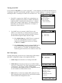
Turning on the MFC
Use the dedicated
ON/OFF
key to power up the MFC. A brief diagnostic runs while the Meriam Process
Technologies logo, MFC model number, and MFC firmware version is displayed. A message is displayed
indicating the MFC is scanning for a HART device at address zero. The following scenarios are possible.
1. If the MFC is connected to a HART device with address zero
(and there is sufficient loop resistance), the MFC immediately
establishes HART communication with the device. A display
similar to the example at right appears. The numbered menus
and Soft Keys are then used to commission, re-configure, or
maintain the connected device.
2. If no HART device is connected, a HART device with
address ≠ 0 is connected, or a connected device is not found
due to wiring or loop resistance problem, the MFC will enter
the MFC Main navigation display depicted at right.
2.1 Select
Online Setup
once a HART device is connected
or once the wiring problem is resolved. A proper
connection will be indicated when line two changes
to “
Device 0 *Online*
”.
2.2 Select
Online Setup
if properly connected HART device
is setup for Multi-drop loop or Burst Mode operation
(device address ≠ 0). The MFC will immediately initiate
a multi-drop poll to find all non-zero addresses on the loop.
MFC Main display
The MFC Main display provides access to Online Setup, Offline Menus
and to MFC configuration settings via the right hand Soft Key.
1.
Online Setup
is described above in Turning On the MFC.
2.
Offline Menu
is selected to provide access to Offline Utilities
such as List / Show DOFs, List / Edit Configurations, and Create
Configurations. The number of DOFs installed (HART
device profiles) and the number of device Configurations stored
are also available on Offline Utilities screen.
3.
MFC
Soft Key is selected to configure MFC settings and view
MFC information such as Model, Serial, and Firmware numbers,
DOFs installed and Configurations stored.
Online #
3051 : PT-1012D
1 Device setup
2 Pres: 0.01 inH2O
3 AO: 4.001 mA
4 LRV: 0.00 inH2O
5 URV: 250.00 inH2O
Up Down Select Back
MFC Main #
Device 0 Not Found
1 Online Setup
2 Offline Menu
Up Down Select MFC
MFC Main #
Device 0 *On-line*
1 Online Setup
2 Offline Menu
Up Down Select MFC
Configuration #
Current Settings
Lockout : Disabled
Backlight: 2 min
Off Timer: Disabled
Clock Edit
Enter PC Comm. Mode
Model Info
Up Down Select Back

7
MFC Configurations Settings
Lockout Feature
The MFC HART Communicator can be programmed to lock out certain standard functions that a supervisor
may wish to control. The functions included are used to set up the MFC for normal use, change online
HART device configurations, create offline HART device configurations, update the installed DOFs list
(HART device profiles), or to update the MFC’s operating firmware. For example, locking out the Configs
feature turns the MFC into a read only HART communicator while locking out DOFs and Firmware prevents
unauthorized updates. The lock out can be limited to individual Lockout Details items or all Lockout Details
items can be locked out at one time.
To enable the lockout feature, move the selection cursor to the
Lockout
menu option on the
Configuration screen (see above). Choose the
Lockout
selection by pressing the
Select
soft key. The MFC
will enter the
Lockout Enable / Disable Screen
. The current status is shown and three choices are provided:
Lockout Enable / Disable Screen
Lockout View Details Screen
Disabled:
All lockout features are disabled and all options on the menu are accessible for reconfiguration.
Enabled:
Enables the lockout selections that are set in the
Lockout Details
screen (above left)
.
View Details:
This option takes the user to the
Lockout Details
screen listing all MFC parameters that can
be protected by lockout (see above left). Individual functions can be locked or, if preferred, the lockout can
be set to deny unauthorized access to all parameters.
To enable the lockout option, select
Enabled
on
Lockout Enable / Disable Screen
by scrolling
Down
and
pressing
Select
. The screen will switch back to the original
Settings
screen that now shows the lockout
status as Enabled.
Scroll
Down
to
View Details,
and press
Select
. This screen allows the user to choose which parameters to
lockout. Use the
Up
and
Down
keys to scroll through the selections and press
Select
to choose the desired
setting(s). The screen will change and prompt you to
Enable
or
Disable
lockout for that function. Scroll
Down
to
Enable
and press
Select
.
Lockout Code
At this point the user will be prompted to enter a 3-digit lockout code. This code will be required to gain
access and change any parameter previously locked out. Use the
Inc
rement,
Dec
rement
and
Next
Soft Keys
to input a lockout code value. Alternatively you may use the green keys for
Inc
rement and
Dec
rement functions. When you are satisfied with the lockout code value, press
Store.
IMPORTANT
: After the code is entered, the user must cycle the power to activate the lockout mechanism!
Configuration #
Lockout Details
All : Disabled
Setting : Disabled
DOFs : Disabled
Configs : Disabled
Firmware : Disabled
Up Down Select Back
Configuration #
Lockout : Disabled
Disabled
Enabled
View Details
Up Down Select Back

8
BE SURE TO SAVE THIS CODE IN A SAFE PLACE IN THE EVENT YOU FORGET THE NUMBER. ACCESS TO
LOCKED-OUT FEATURES WILL BE DENIED WITHOUT THE PROPER CODE.
To Disable Lockout
When you wish to use a function or edit a value that is protected by the lockout code, enter the three digit
Lockout code when prompted and press
Save
. You will now be able to use the function or edit the setting as
normal. Entering an incorrect code will display the message “Incorrect Code” and allow you to try again.
Changing the Lockout Code
To change the lockout code, disable the lockout function for all the parameters selected, shut the unit off, and
follow the procedures outlined above.
Backlight (off timer)
To conserve battery life, the MFC 4100 series allows the user to set the backlight to shut off after a certain
period of keypad inactivity. To change the backlight off timer on the unit, scroll
Down
to
Backlight
and
press
Select.
Scroll
Up
or
Down
to the auto shut-off time desired. Press
Save
to select the new value.
The shutoff timer can be disabled or set to shut off after time periods of from 1 minute up to 30 minutes.
NOTE: The Backlight Off Timer is disabled when the optional AC Adapter (P/N A36742) is powering the MFC.
Off Timer
To conserve battery life, the MFC 4100 series allows the user to set the unit to shut off after a certain period
of keypad inactivity. To change the off timer on the unit, scroll
Down
to
Off Timer
and press
Select.
Scroll
Up
or
Down
to the auto shut-off time desired. Press
Save
to select the new value.
The shutoff timer can be disabled or set to shut off after time periods of from 1 minute up to 2 hours.
NOTE: The Off Timer is disabled when the optional AC Adapter (P/N A36742) is powering the MFC.
Clock Edit
The Clock Edit option allows the user to correct the date and time of the MFC’s internal clock. To select the
Clock Edit
feature, make sure the pointer arrow is pointed to this selection. If not, scroll the arrow
Down
using the soft keys. Choose
Clock Edit
by pressing the
Select
soft key.
Choose a clock or date option to adjust by scrolling
Up
or
Down.
Press
Select
to choose that option. Enter
the correct value using the numeric keypad and text edit key if needed. When complete, press
Done
. You
will be asked if you wish to save the new data. Press
Yes
to accept the new value. Pressing
No
will take you
back to the
Clock Edit
without making any changes to the MFC clock.
NOTE: When replacing the batteries, the date and time will remain active. Date & time information is
continuously powered by an internal, 10-year life back-up battery. This battery is not serviceable by the
user.
Enter PC Comm. Mode
When the MFC is connected to a PC for updates via MFx Installer (see MFx Installer section in this manual),
a DB-9 serial cable is used. Occasionally a DB-9 Serial cable is encountered that does not have a DTR line.
The DTR line is important to the update process because it is used to initiate and confirm communication
between the two machines. If a DB-9 cable without a DTR line is used, the MFC must be manually placed

9
in the
Enter PC Comm. Mode
. Go to the MFC Main display and select
MFC
. Scroll down to the
Enter
PC Comm. Mode
menu option and press
Select
. Proceed with update and cycle MFC power when the
update is complete. It is recommended to use fresh batteries or an AC adaptor during update procedures.
This mode will automatically time-out after approx. 2 minutes of inactivity and return to the main display.
Battery Installation & Removal – all MFC models
The MFC monitors battery condition and displays a “REPLACE BATTERY” notice when the batteries get
low. The MFC will function for a short period of time after the notice is posted.
To install or remove the batteries, remove any soft case or protective boot and turn the MFC face down on a
work surface. Use a flat screwdriver to loosen the captive screw holding the battery door closed and remove
door. Replace batteries and make sure all connections are firmly secured. Replace door, tighten screw and
replace the soft case or boot.
Note: Replace both 9-volt batteries at once with all alkaline, all lithium or all NiMH cells. Do not mix
alkaline, lithium or NiMH batteries with each other or with other battery types. Battery replacement is
recommended when the “Replace Batteries” notice is posted on the display; however, the MFC will
function for a time after the notice is posted.
Note: For Intrinsically Safe MFC models, replace batteries only in Non-Hazardous Areas. Replace
batteries with approved types only. See the MFC Intrinsic Safety Control Document in the Appendix of
this manual for approved battery details.
External Connections to MFC
1. AC Adapter
– The MFC 4100 can be powered by external AC Adapter connected to the jack located on
the left side of the MFC. P/N A36742 bypasses the battery circuit to power the unit. The battery symbol in
the display header is replaced by a wall plug symbol.
WARNING: Serious injury or death may result from explosions. Do not make connection to the AC
adapter jack in a hazardous area. Use the AC adapter only in non-hazardous areas.
2. HART lead set –
All MFC models are equipped with a standard size banana jack on 0.75” center. The
lead set supplied with the MFC has a standard banana plug on one end and mini-grabbers on the other for
convenient connections.
Note: For Intrinsically Safe MFC models, verify the instruments in the loop are installed in accordance
with intrinsically safe field wiring practices before making connection from the field device to the MFC’s
HART jack. See Hazardous Area Use Section of this manual for Intrinsically Safe guidelines /
restrictions.
3. DB-9 Connection Port
– All MFC models are equipped with a standard DB-9 connection for RS-232
communications located on the MFC’s bottom end. The DB-9 provides the hardware interface to facilitate
download / upload operations from a host PC. This connection port facilitates download of MFC firmware
improvements, HART
®
Device Object Files (DOFs) and documenting operations (Documenting options
pending). All MFC upgrades are available via the Meriam Process Technologies Download Site accessible
from www.meriam.com. The MFC will not need to be returned to Meriam for firmware updates or for the
addition of DOF files.
Note: Do not use the DB-9 connection port in Hazardous Areas. Use in non-hazardous areas only. See
Intrinsic Safety Control Document in the Appendix for more details on I. S. MFC units.

10
HAZARDOUS AREA USE
Intrinsically Safe Certification
The MFC 4102 and MFC 4103 HART Communicators are available with Intrinsically Safe Certification for
use in Class I, Division I, Groups A, B, C, and D, T5 hazardous areas. Refer to the Intrinsically Safe Control
Document in the Appendix of this instruction manual for more details. The certification is to CAN /CSA-
22.2 No.1010.1 & 157-92 and UL913 Fifth Edition Rev 2/21/97.
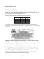
The following table identifies MFC model numbers and Areas of acceptable use.
Model Number Non-hazardous
Area
Hazardous
Area
MFC 4100 √ NO
MFC 4101 √ NO
MFC 4102 √ √
MFC 4103 √ √
MFCs with Intrinsically Safe certification can be identified by model number (see table above or the
Intrinsically Safe Control Document in the Appendix) or by a special label on the unit. A sample of the label
is shown below.
WARNING: Serious injury or death may result from explosions. Do not make connection to the DB – 9
connection port or to the AC adapter jack while in a hazardous area.
WARNING: Serious injury or death may result from explosions. Before making electrical connections to
an Intrinsically Safe MFC at the HART jacks, verify the instruments in the loop are installed in
accordance with intrinsically safe field wiring practices.
Note: Restrictions apply to the use of Intrinsically Safe MFC units in hazardous areas. Refer to the
Intrinsically Safe Control Document in the Appendix for exact details. Meriam Process Technologies
reserves the right to revise the Control Document without notice. Contact Meriam Process Technologies
(phone (216) 281-1100) for the current Intrinsically Safe Control Document.
For Intrinsically Safe MFC models, consult the
Hazardous Area Use
section of this manual for
restrictions, for special instructions in use, and for electrical connections.

11
HART
®
Communications with the MFC 4100
Overview
The MFC 4100 HART communicator provides device specific HART communication functions that
allow the user to poll, configure and maintain supported HART field device. The MFC 4100 uses
Universal, Common Practice and Device Specific commands to facilitate communication with a HART
field device. Use the MFC to commission devices, operational re-configuration needs, or maintain
devices through analog and sensor trim adjustments and many other features.
The MFC 4100 will communicate with any HART device through Universal and Common Practice
Commands using the standard Generic DOF (Device Object File) but must have the DOF for a specific
HART device installed before it can execute Device Specific Commands. Consult the large and growing list
of available DOFs at www.meriam.com
for an up to date list of HART devices with device specific support.
The list is found under “Available DOFs” button on the home page. When HART device support for new
devices becomes available, the MFC can be easily field updated via Internet downloads.
HART Commands
Three HART command types are used by the MFC 4100 to communicate with HART field devices. First,
Universal Commands are primarily used to identify a field device by its model number and tag number and
to read process data from the device. This communication is referred to as “polling”. The MFC 4100 can poll
any Hart Device. Second, Common Practice Commands are used for calibration and maintenance functions
that are common to many devices. An example of this would be trims or adjustments for the devices’ analog
outputs. Third, Device Specific Commands are used to handle functions that are unique to a particular device
or manufacturer. Examples of these commands include sensor zero, sensor trim, calibration curve
characterization, density inputs required for calculations made by the HART device or other configuration
functions unique to the specific device.
HART Connections
HART connections are made using two standard banana jacks (3/4” center) located at the top end of the
MFC 4100. Refer to the following diagram. Polarity is not a concern for HART connections so both jack
collars are black. Meriam supplies a HART lead kit (P/N A36744) complete with mini-grabber connections
and a 250 Ω load resistor with each model MFC 4100.
For low load loops (less than 250 Ω), a 250 Ω resistor will need to be added to the loop to insure reliable
HART communications. Meriam supplies a 250 Ω load resistor in the form of a standard adaptor (P/N
A36821). Refer to the following diagram for connection details.
MFC 4100 with HART
®
HART
®
connections are standard banana jacks (3/4” center)

12
When connecting the MFC 4100 to a loop with a resistive load greater than 250 Ωs, the HART jacks may be
connected across the loop + and – or to the HART device communication terminals. Refer to the following
diagram for connecting across the loop + and -.
HART
®
Communications
Upon power up the MFC automatically detects if a field device is connect and attempts to establish HART
communications. When a device with address zero is found, the MFC provides feedback to the user and
starts the initial HART display for the connected device. See an example of Online Mode below.
Connecting to the MFC communication terminals
Online #
3051 : PT-1012D
1 Device setup
2 Pres: 0.01 inH2O
3 AO: 4.001 mA
4 LRV: 0.00 inH2O
5 URV: 250.00 inH2O
Up Down Select Back
Online HART Screen

13
When no device connection is detected or a device with non-zero (Multi-drop or Burst Mode) address is
found, the message
Device 0 Not Found
is displayed and the MFC enters the
MFC Main
navigation
screen. The
MFC Main
screen allows the user to launch a multi-drop poll to find all devices with non-zero
addresses on the loop, to manually start an Online poll, or to enter Offline Mode.
Multi-drop Poll
To initiate a Mult-drop Poll, select the
Online Setup
option from the
MFC Main
screen when the
Device 0
Not Found
message is displayed. This function polls for all non-zero addresses (1 – 15). Located addresses
are listed on the display as the remaining addresses are checked. When polling is complete, or upon pressing
Stop
after the address of interest is found, use the soft key controls to select the address of interest. The
initial HART menu for the device selected will then be displayed for use.
Manual Launch of Device 0 Poll
When the message
Device 0 *On-line*
is displayed on the MFC Main navigation screen, selecting
Online Setup
will launch HART communication with the device. The message indicates that a HART
device with address 0 has been detected at the HART connection and the MFC is standing by to initiate
communications. The
Device 0 *On-line*
message is shown 1) if a physical connection is made to a
HART device after the MFC power is turned on or 2) if the user exits from a HART communication
session using the soft key controls provided.
Offline Menu Mode
The
Offline Menu
gives the user access to lists and functions that can be viewed or performed in Offline
Mode at the user’s convenience for the purposes of reviewing the MFC’s DOF list, reviewing stored device
configurations or creating HART configurations. Stored configurations can be also be edited and then
applied later to a connected HART device. When the
Offline Menu
is selected from the
MFC Main
navigation screen, the following display is shown.
MFC Main Navigation Screen
No device or Non-zero address found
MFC Main #
Device 0 Not Found
1 Online Setup
2 Offline Menu
Up Down Select MFC
MFC Main Navigation
Screen
Manually launch polling on Device 0
MFC Main #
Device 0 *On-line*
1 Online Setup
2 Offline Menu
Up Down Select MFC
MFC Main #
Multidrop Polling…
Scanning Address #
Stop Abort
Mult-drop Polling Screen
Multi-drop & Burst Mode Support
Offline #
Utilities
1 List/Show DOFs
2 List/Edit Configs
3 Create Configs
4 Delete All Configs
DOFs Installed: 154
Configs Stored: 3
U
p
Down Select Back
Hart Offline Menu Screen

14
List / Show DOFs:
Provides a list of installed DOFs (Device Object Files) used by the MFC to communicate with HART
devices. Lists can be view by Manufacturer, by Device Name or by stepping through all Devices one at a
time. Use the soft key controls to move through the list. Pressing the SHIFT key changes soft key
definitions
Down
and
Up
to
PgUp
and
PgDn.
To quickly advance to the next page of a list, press
SHIFT
and then the
PgDn
soft key. To retreat to the prior page, press
SHIFT
and then
PgUp
. Once engaged, the
PgUp
and
PgDn
soft keys remain active until the
Up
or
Down
soft keys or
SHIFT
is pressed again.
.
List / Edit Configs:
This screen lists all stored HART configurations by Tag Number. The
configurations stored enable fast commissioning of replacement devices,
cloning of existing systems, or re-configuring for changes in process
conditions or batch runs. Any configuration in the list can be sent to
another HART device of the same manufacture and model. The display
can show 20 character tag numbers. Truncated tags are listed if more than
20 characters are used. Moving the cursor down to the tag of interest and
pressing the
Select
soft key will provide a detailed information screen,
including full tag number up to 28 characters, for the tag of interest (see
example below, right).
The editing function allows review of all HART parameters in a config-
uration and modification of editable parameter. The edit function can be
locked out if desired (see the
Lockout
section of this manual for more
information). To view detailed information of a stored configuration, Move
the cursor to the desired tag number and press the Select soft key. The
Config Detail screen (see example at right) provides information to help
the user confirm the identity, origin, and save date/time of the configuration.
Pressing Select again opens the configuration for review or offline editing.
New configurations saved are added to the bottom of the List / Edit Config
list. If multiple entries for one device are shown, the most recently saved
configuration is always shown at the bottom.
Entries in the List / Edit Config list may have been saved or created from
various sources. Possible sources include the save command from a
connected HART device, created in the MFC using the
Create Configs
function, copied from another configuration and renamed, or created by
editing an existing file. An MFC with Documenting option (MFC 4101,
MFC 4103) will also list configurations downloaded from the separately
available Device Management System software from Meriam (see www.meriam.com/dm_solns.htm for
more information). Tag numbers, date / time of save, type of configuration stored, and other information
are displayed under
List/Edit Configs
. Configuration types are:
Complete Config = saved from connected device in Online mode, or a
complete config that was downloaded from DMS
Default Config = created by MFC in Offline mode, or created in DMS
and downloaded to MFC
Edit Vars Only = created by editing an existing configuration and includes only the edited parameters
MVar Primary Cfg = for multivariable devices – Primary Variable configuation
MVar Sub Config = for multivariable devices – Sub-configuration (secondary, tertiary, fourth, etc
variables)
Offline List / Edit
Configs Screen
Offline #
List/Edit Configs
PT-105A
PT-105B
DPT-201C
TT-312A
TT-312A
FE-201
FE-201
PT-6174
Up Down Select Back
Offline #
List/Edit Configs
Tag: PT-105A
Device ID 1365
PV: Pressure
Endress + Hauser
Cerabar S
Complete Config
Uses DOF 11070702
51 Variables
12/18/03 4:58 PM
Copy Del Select Back
Offline List / Edit
Configs Detail Screen

15
Create Configs:
The
Create Configs
function allows the user to configure a HART device file in Offline Mode for sending
to the intended device later when connected in the Online Mode. Use the soft key controls to move through
the list and select the device model number required. The menus prompt the user to make the necessary
configuration selections, tag the file for later retrieval and use, and edit configuration lines as required. This
function can be locked out. See the Lockout Section of this manual for more information.
Delete All Configs:
The
Delete All Configs
function clears
all
configurations from memory (including active and hidden
configs). When this menu option is selected, the MFC will ask “Delete ALL Configs… ARE YOU
SURE???” Select
Yes
to clear
all
stored configurations from memory.
Delete Configs / Clearing Configuration Memory:
Individual stored Configurations may be deleted with MFC
Del
soft key
functions (see example at right). A delete confirmation screen is provided
to prevent unintended deletions. The
Del
key only hides the record from
the MFC screen; it does not clear memory space. The editing function
can be locked out. See the Lockout Section of this manual for more
information.
(To clear
all
configurations from memory (including active and hidden
configs), enter the
HART Offline Menu Screen
and select the
Delete
All Configs
option. The MFC will ask “Delete ALL Configs… ARE
YOU SURE???” Select
Yes
to clear
all
stored configurations from
memory.)
Online Setup Mode
Online Setup is the normal HART communication mode for the MFC.
This mode enables communication with HART field devices at the
Universal, Common Practice and Device Specific Command levels for
full device setup and functionality.
Menus displayed for the connected device follow the HART device
manufacturer’s menu structure for the connected device. Consult
the device manual for menu structure details.
MFC features two unique online features for added convenience to the
user.
1. Live HART connection monitor: MFC display lets you
know from the Main navigation screen when a device is
*
On-line
*
and ready for communication.
2.
Review/Edit
: this menu option allows the user to review
configurations line-by-line. MFC supports editing of the
configuration once the line of interest is located.
Communications Trouble Shooting
If an operating HART device is connected to the MFC but the “Device 0 Not Found” notification is
received, a Multidrop Poll
may be executed to determine if the connected device has a non-zero address.
Device Setup #
3051 :PT-1012D
1 Process variables
2 Diag/Service
3 Basic setup
4 Detailed setup
5 Save/Send
6 Review/Edit
Up Down Select Back
Online Device
Setup Screen
Offline #
List/Edit Configs
Tag: PT-105A
Device ID 1365
PV: Pressure
Endress + Hauser
Cerabar S
Complete Config
Uses DOF 11070702
51 Variables
12/18/03 4:58 PM
Copy Del Select Back
Offline List / Edit
Configs Detail Screen

16
Select
Online Setup
from the MFC Main navigation screen to initiate the multi-drop poll. If the “No
Devices Found” message is received, then the loop connections to the MFC should be carefully checked.
If an operating HART device with address zero (0) is connected to the MFC but the “Device 0 Not Found”
notification is received, the loop connections to the MFC should be carefully checked.
Make sure all connections are correct and secure. Check for shorts, open circuits and multiple grounds.
Determine if the loop resistance is greater than 250Ω and less than 1100Ωs. If less than 250 Ω then use the
supplied 250 Ω load resistor in series with the loop (see diagram HART Connections section).
If communication is still not established, check the
List / Show DOFs
menu under
Offline Menu
. Check
the list for the presence of the “Generic” DOF under the manufacturer name “Meriam.” If “Generic” is
found, then HART communication is possible when the device is properly wired and connected to the MFC
(see connection troubleshooting details above).
When the message “Generic” is displayed after connecting to a HART device there are two possible causes:
1) No device specific DOF for that device is currently installed in MFC memory. Check the Meriam
Download Site for availability of the DOF needed by clicking on the Download Site button at
www.meriam.com
and entering the User Name and Password provided with MFC shipment. For
download instructions, see the DOF Download Site Information section of this manual.
2) The Meriam DOF “Device Library” is missing or has become corrupted. Without this DOF, the
MFC may not recognize a connected device. Check the
List / Show DOFs
menu option of
Offline
Menu
More Status Message
HART device events (diagnostic flags) cause the MFC to display a “More Status Message” at the bottom
of the display. This message is a notice to the user that one or more diagnostic warnings are available in
the Review Status menu option of the connected device. Upon receipt of this message, enter the
HART
mode and select Detailed Setup / Diagnostics – Service / Test – Status / View Status to retrieve the
diagnostic information.
Save / Send Configuration Functions
HART device configurations may be saved to MFC memory or sent from MFC memory to a HART
device in all MFC model numbers. These functions are useful for cloning a device configuration for use
in another transmitter of the same configuration, for recording as-found and as-left configurations for later
review, for returning HART devices to previously used configurations, etc…
The Save / Send function may be accessed in one of two ways:
1. Press the Document key on the MFC for the
screen shown at right. Then select the “Save/Send
Configs” menu option to launch a HART communi-
cation poll and use the Save / Send options.
2.
Use the Save / Send menu option within the HART
device’s standard menu. The MFC would be in
Online mode in this case. Save / Send is normally
found under the “Device Setup” menu option on the
initial HART display for the device.
Document #
Utilities
1 Save/Send Configs
2 List/Edit Configs
3 Create Configs
Configs Stored: 98
Up Down Select Back
Document Key Menu Screen
Page is loading ...
Page is loading ...
Page is loading ...
Page is loading ...
Page is loading ...
Page is loading ...
Page is loading ...
Page is loading ...
Page is loading ...
Page is loading ...
Page is loading ...
-
 1
1
-
 2
2
-
 3
3
-
 4
4
-
 5
5
-
 6
6
-
 7
7
-
 8
8
-
 9
9
-
 10
10
-
 11
11
-
 12
12
-
 13
13
-
 14
14
-
 15
15
-
 16
16
-
 17
17
-
 18
18
-
 19
19
-
 20
20
-
 21
21
-
 22
22
-
 23
23
-
 24
24
-
 25
25
-
 26
26
-
 27
27
-
 28
28
-
 29
29
-
 30
30
-
 31
31


Meriam MFC 4102 HART Operator's Instruction Manual
- Type
- Operator's Instruction Manual
- This manual is also suitable for
Ask a question and I''ll find the answer in the document
Finding information in a document is now easier with AI
Related papers
-
 Meriam HART 5150 Series Quick start guide
-
 Meriam MFC5150 HART® Communicator Quick start guide
-
 Meriam MFC5150 HART® Communicator Product User Manual
-
 Meriam MDT500 Multivariable Transmitter Product User Manual
-
 Meriam PIT5000 Pipeline Integrity Tester Quick start guide
-
 Meriam VMA0055 Module Product User Manual
-
 Meriam M4 Series Quick Use Manual
-
 Meriam meriGauge® Plus Digital Gauge Product User Manual
-
 Meriam M200DI Wet/Wet Differential Pressure Smart Manometer Product User Manual
-
 Meriam M1500 Analog Pressure Transmitter Product User Manual


Other documents
-
 Fisher-Rosemount 00275-8026-0001 User manual
-
 Brooks 4800 Series User manual
-
 ANDERSON-NEGELE MPP Installation And Startup Manual
-
Fluke HART 744 User manual
-
KLINGER 451 Operating instructions
-
Sierra Monitor Corporation 4100-36 User manual
-
 Brooks 4800 User manual
-
 Brooks SLAMf50 / SLAMf60 / SLAMf51 / SLAMf61 / SLAMf53 / SLAMf63 / SLAMf64 Operating instructions
-
 Enabling Devices 7083 User manual
-
 Meriam Instrument M2 Series User manual


