Page is loading ...

MFT 4000 Calibrator
MFT 4005 Calibrator with HART® Trims
MFT 4010 Calibrator with HART® Communications
USER’S MANUAL
File No. MFT 4000:440-6
Firmware: v 4.0 & greater
Nov. 2006

MFT 4000 SERIES USER’S MANUAL
Models
MFT 4000 Modular Calibrator
MFT 4005 Modular Calibrator with HART® Trims
MFT 4010 Modular Calibrator / HART® Communicator
IMPORTANT NOTICE
ASSISTANCE
For customer assistance please contact Meriam directly either by phone at (216) 281-1100, or by e-mail at
HART® is a registered trademark of the HART Communication Foundation.
Meriam Process Technologies
10920 Madison Avenue
Cleveland, OH 44102
TELEPHONE: (216) 281-1100
E-mail: meriam@meriam.com
Web Site: www.meriam.com
Important information on the product is contained in this
manual. Read this manual carefully and completely before
operating the product. For the safety of the operator and the
system, a thorough understanding of this manual is necessary
before commissioning, using or maintaining the product.

MFT 4000 / 4005 / 4010 User’s Manual
TABLE OF CONTENTS
Subject Page
MFT 4000 Overview ...................................................................................................................................1
Keypad Overview........................................................................................................................................1
Single Function Keys.............................................................................................................................1
Dual Function Keys ...............................................................................................................................2
Soft Keys ...............................................................................................................................................3
Alphanumeric / Symbol Entry ................................................................................................................3
Alternative Numeric Data Entry .............................................................................................................4
Measure Mode............................................................................................................................................4
Header-line Symbols .............................................................................................................................4
Display Screen............................................................................................................................................5
Soft Key Options.........................................................................................................................................5
Zero .......................................................................................................................................................5
Mn/Max ..................................................................................................................................................5
Damp .....................................................................................................................................................5
More.......................................................................................................................................................6
Hold .......................................................................................................................................................6
Sensr .....................................................................................................................................................6
Rcal........................................................................................................................................................6
Pon ........................................................................................................................................................6
Poff ........................................................................................................................................................6
Vrng .......................................................................................................................................................6
MFT Configuration Settings........................................................................................................................7
Users .....................................................................................................................................................7
Measurement ........................................................................................................................................7
Damping ............................................................................................................................................7
Units of Measure ...............................................................................................................................7
Applications ...........................................................................................................................................7
Digital Poll.........................................................................................................................................7
EJA / EJX Accuracy Utility (Yokogawa)............................................................................................8
Lockouts ................................................................................................................................................9
Master Lockout .................................................................................................................................9
PV Prompt ........................................................................................................................................9
Unlocking the MFT ...........................................................................................................................9
Changing the Lockout Code.............................................................................................................9
Clock/Timers .......................................................................................................................................10
Others..................................................................................................................................................10
Model Info.......................................................................................................................................10
Battery (Type Select for accurate battery indicator).......................................................................10
HART (Communication Master Setting) .........................................................................................10
Enter PC Comm. mode ..................................................................................................................10
General Operation ....................................................................................................................................11
Sensor Installation/Removal...............................................................................................................11
Change Units / Removing & Restoring Sensors on Display ..............................................................11
Sensor Module Engineering Units......................................................................................................12
Installation & Removal of Batteries – Standard MFTs........................................................................12
Installation & Removal of Batteries – Intrinsically Safe MFTs............................................................12
Over pressurization – Pressure Modules ...........................................................................................13
Media compatibility – Pressure Modules............................................................................................13

TABLE OF CONTENTS, con’t
Subject Page
Applications ..............................................................................................................................................14
Gauge Pressure Calibration .................................................................................................................14
Differential Pressure Calibration...........................................................................................................15
Additional DP Application Information ..................................................................................................15
Vacuum and Absolute Pressure Calibration.........................................................................................16
Electrical Connections ..............................................................................................................................17
Milliamp transmitters.............................................................................................................................17
Voltage transducers..............................................................................................................................17
Field Recalibration................................................................................................................................... 18
DB-9 Connection Port...............................................................................................................................20
Hazardous Area Use (Intrinsically Safe Option).......................................................................................21
MFT 4000 Series - Model Specific Features ............................................................................................22
Calibrate Key – MFT 4000, MFT 4005, MFT 4010................................................................................... 22
Procedure (Manual, From PC, Template) ........................................................................................... 23
Device Output (Conventional mA / V, HART mA, HART PV, User Entry……………………………… 23
Cal Type (P, RTD, TC, VMA, I/P, P/ I, Switch, Loop Test) ................................................................. 24
Loop Test............................................................................................................................................. 24
Quick Cal ............................................................................................................................................. 26
Smart Trim ........................................................................................................................................... 27
4 mA Analog Trim........................................................................................................................... 27
20 mA Analog Trim......................................................................................................................... 27
Zero Trim........................................................................................................................................ 28
Lower Sensor Trim ......................................................................................................................... 29
Upper Sensor Trim......................................................................................................................... 29
View Results ........................................................................................................................................ 30
Clear Cal Memory............................................................................................................................... 31
Documenting Calibration Results ............................................................................................................. 32
Entering Calibration Documentation Mode........................................................................................... 33
Manual Calibration Procedures and Documentation............................................................................ 34
Local Indicators or Fieldbus Device Calibration Procedures and Documentation ............................... 38
From PC (Stored) Calibration Procedures and Documentation ........................................................... 39
Template Calibration Procedures and Documentation (Manual) ......................................................... 42
Loop Test Calibration Procedures and Documentation – Manual........................................................ 43
Loop Test Calibration Procedures and Documentation – From PC (Stored)....................................... 46
Switch Test Calibration Procedures and Documentation – Manual ..................................................... 46
Switch Test Calibration Procedures and Documentation – From PC (Stored) .................................... 50
Deleting Files and Clearing Documentation Memory ........................................................................... 50
MFT 4005 with HART® Trims ................................................................................................................... 51
MFT 4010 with HART® Communications ................................................................................................. 52
HART Commands................................................................................................................................. 52
HART Connections............................................................................................................................... 52
HART Communications ........................................................................................................................ 53
Communications Trouble Shooting ................................................................................................ 53
Multidrop Polling (addresses 1 – 15).............................................................................................. 54

TABLE OF CONTENTS, con’t
Subject Page
Digital Polling (addresses 0 – 15)................................................................................................... 54
Manual Launch of Device Poll........................................................................................................ 54
Cloning HART devices ................................................................................................................... 54
Saving Configurations for Multivariable HART devices (PV Prompt)............................................. 55
More Status Message..................................................................................................................... 55
HART Offline Mode............................................................................................................................... 55
List/Show DOFs.............................................................................................................................. 55
List/Edit Configs.............................................................................................................................. 56
Create Configs................................................................................................................................ 56
Delete Individual Configs / Clear Configuration Memory ............................................................... 56
HART Online Mode .............................................................................................................................. 56
Device Configuration ....................................................................................................................... 57
Pressure Trim .................................................................................................................................. 61
Analog Trim ..................................................................................................................................... 63
Scaled D/A Trim..............………………………………………………………………………………… 64
Loop Test......................................................................................................................................... 66
Basic Info ......................................................................................................................................... 67
HART Output ................................................................................................................................... 68
Diagnostics ...................................................................................................................................... 69
Review/Edit...................................................................................................................................... 71
Quick Menu Key (HART support key) ...................................................................................................... 71
DOF Memory Maintenance ...................................................................................................................... 72
MFT 4010 Device Specific & Generic HART Communications................................................................ 73
Documenting HART Configurations with Meriam DMS............................................................................ 73
Download Site Information – DOFs, Firmware, Utilities ........................................................................... 73
Who has access to the Download Site ................................................................................................. 73
PC Requirements for Download Operations ........................................................................................ 74
Preparing the MFT for Updating........................................................................................................... 74
Preparing to Download ......................................................................................................................... 74
Using the Download Site ...................................................................................................................... 74
Subscriber Options ............................................................................................................................... 74
DPC Manager Installation Utility........................................................................................................... 74
Returning the MFT for Repairs ................................................................................................................. 75
APPENDIX
Product Specifications Overview.......................................................................................................... 76
Models, Options, Ordering Information ................................................................................................ 78
Sensor Modules List ............................................................................................................................. 80
MFT Accessories List ........................................................................................................................... 81
TIO0110 T/C Measurement and Simulation Module Instruction .......................................................... 82
VMA0055 Voltage and Current Module Instruction .............................................................................. 86
RIO4000 RTD Measurement and Simulation Module Instruction ........................................................ 92
Intrinsic Safety Control Document...................................................................................................... 105
HART Command Structure Menu Tree Examples ....................................................................106 - 109

1
MFT 4000 SERIES OVERVIEW
The MFT 4000 Multi-Function Tester (MFT) is a modular calibrator with three sensor bays accommodating up to three
independent pressure, temperature or special function modules. The base MFT incorporates a voltage and current
meter, several keys for user interface and will display up to four measurements simultaneously. The MFT 4005 adds
HART trim capabilities for one-tool calibration of HART pressure and temperature devices. The MFT 4010 adds full
HART communication capability to the same handheld base unit for greater flexibility and versatility in commissioning,
reconfiguring, and maintaining HART field devices including analytic, flow, level, pressure, temperature, and valve
categories.
Note: For Intrinsically Safe MFT models, consult the Hazardous Area Use section of this manual for specific
details on use of approved MFTs and applicable restrictions.
KEYPAD OVERVIEW
The following is an overview of the MFT 4000 series keypad operations. The MFT keypad has three basic key types
(the functions of each are described below): Single function keys, dual-function keys, and soft keys. Single function
keys control a dedicated MFT function. Dual-function keys, through the use of the Function key, control two
separate functions. Soft key functions change depending on the operating mode. Their definitions are displayed at
the bottom of the LCD, just above each white soft key.
Single Function Keys
On/Off
Pressing the On/Off key powers up the MFT. As the unit powers up, it performs an internal diagnostic check
of its systems. Any abnormalities are posted on the display. The unit will briefly display the MFT model
number and the installed sensor module ranges and bay locations (S1, S2, or S3) before the unit enters the
Measure Mode.
Back Light
The MFT has a back light feature with two light intensities. Toggle this key from Off to Low intensity back light
to high intensity to Off again. A back light off timer is available under the Settings key to help conserve
battery life.
Measure Mode
Pressing the Measure Mode button will instantly return the unit to measure mode from any menu or sub-
menu. Measure will appear on the upper left of the display.
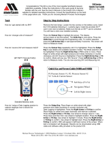
Soft Ke
y
s
Dual Function Keys
Voltage / mA Jacks
Single Function Keys
AC Adaptor Jack
HART Jacks
LCD
DB-9 RS232 Connection
Module Bays (3)

2
Display Contrast
This key allows the user to adjust the contrast of the LCD display for ambient conditions or user preferences.
Pressing and holding this key will cycle through all available contrast settings. If over-adjusted, simply release
key for one second and re-press to change direction of adjustment. After adjusting Contrast, wait at least five
(5) seconds before turning unit off to insure storage of new contrast setting.
Function
The Function key is pressed to access the functions labeled in blue on the dual-function keys. Pressing the
Function key will allow the user to access and/or alter the corresponding properties. Function remains on
until it is depressed again. When the Function key is active, an up arrow ( ) will appear at the top of the
display to the left of the battery power or AC wall plug icon.
Dual Function Keys
S1 Units
The S1 Units key changes the engineering units for the module in sensor bay 1. The Function key
must be active before the units can be changed. When numeric entry is anticipated by the MFT, this key can
be used to toggle from 1 to 2 to 3 and back to 1 for entry purposes.
HART (Active only with MFT 4010)
The HART key puts the MFT 4010 series calibrator into its HART Communications mode and initiates
communications via the HART connections at the bottom of the MFT.
Units Sensor2
The S2 Units key changes the engineering units for the module in sensor bay 2. The Function key must be
active before the units can be changed. When numeric entry is anticipated by the MFT, this key can be used
to toggle from 4 to 5 to 6 and back to 4 for entry purposes.
Settings
Provides access to the settings menu. This menu shows the current unit settings and allows the user to
customize MFT settings. See Settings section for more details.
Units Sensor3
The S3 Units key changes the engineering units for the module in sensor bay 3. The Function key must be
active before the units can be changed. When numeric entry is anticipated by the MFT, this key can be used
to toggle from 7 to 8 to 9 and back to 7 for entry purposes.
Quick Menu (Active only with MFT 4010)
This key provides a list of frequently used HART configuration and maintenance function menus. User can
quickly scroll to any desired menu. Also, pressing and holding this key from Measure Mode will enter the
HART Offline Menu.
Units mA / V
Toggles between voltage, current (mA), and off display for the integral voltage and current meter. This
measurement is designated by “V/I” on the display. When numeric entry is anticipated by the MFT, this key
can be used to toggle from 0 to (decimal point) to (negative sign) and back to 0 for entry purposes.
Calibrate
This key enters the MFT into calibration & documentation mode for local indicators, conventional transmitters,
HART transmitters, Fieldbus transmitters, and mA loop calibrations.

3
Soft Keys
Soft Keys (unlabled)
The four white keys located below the display are the Soft Keys. The specific functions
of these keys change depending on the operating mode of the MFT. Current defintions
are displayed at the bottom of the LCD display.
Alphanumeric / Symbol Entry
For MFT applications requiring alpha, numeric, and symbol entry (examples: tagging or messaging), the MFT
uses three display grids, the FUNCTION key to change from one grid to another, and four soft keys used for
cursor movement and selection of characters and text. MFT and HART communication functions that require
alpha and numeric entry automatically call up the appropriate grid and make the other grids accessible using
the FUNCTION key. Row and Column soft keys are used to move the flashing cursor through the displayed
grid. The Select soft key enters the indicated character in the text line and the Done soft key accepts the
displayed text line and returns the MFT to service.
Character grids are provided for numeric, alpha, and symbol characters to permit complete editing of text fields.
Each grid includes back space (), forward space (), delete (del) and space (spc) operators to accommodate
text editing needs.
User Interface
The displays shown below illustrate the alphanumeric entry grids and soft key functions. Pressing the MFT’s
FUNCTION key changes the display from one grid to another allowing text messages to be developed using all
three grids when needed.
When using any character grid, pressing Row or Col keys will move the flashing cursor one character across or
down the grid. Pressing and holding the Row or Col key causes the cursor to advance down or across,
respectively, at a regular rate. Releasing the key when the cursor is under the desired character stops the
cursor movement and allows the selection of the character using the Select key. Press the Done soft key
when the character string is completed to enter the string and continue MFT operations.
Numeric Entry: Many HART functions require only numeric entry. For these functions the MFT uses an
Increment and Decrement scheme to change the input field one place at a time. Press the Inc / Dec soft keys
to move through a scroll of -, . , 0, 1…9, and space until the desired value is displayed. Press the Next soft key
to enter that value and advance to the next place in the input field. Repeat as necessary. Press the Done soft
key to end the numeric entry session.
HART
Tag No PT-3456
@ [ \ ] ^ “
” # $ % ( ) ’
& * + . / :
; < = > ? , !
> < del spc
PT3456 OUTPUT < 50% @_
Row Col Select Done
HART
Tag No PT-3456
A B C D E F G
H I J K L M N
O P Q R S T U
V W X Y Z .
> < del spc
PT_
Row Col Select Done
HART
Tag No PT-3456
1 2 3
4 5 6
7 8 9
. 0 +
> < del spc
PT3456_
Row Col Select Done
Alpha entry grid Numeric entry grid Symbol grid

4
Alternative Numeric Entry: When the MFT is in a mode expecting numeric entry from the user, a coded
numeric entry system becomes operational. Four of the main keypad buttons (see below) become active for
direct number entry. For example, use this feature to enter simulation values for VMA0055, TIO0110, or
RIO4000 modules, entering URV or LRV during HART communications, or setting the internal clock. Use the Å
and Æ soft keys to move the cursor to the desired location. For a number 3, press the “S1 Units” key three
times. For an 8, press the “S3 Units” key twice.
MEASURE MODE
After the MFT performs its power up diagnostics and displays the model number and sensor data, it defaults to the
Measure Mode. The word Measure appears on the upper left of the display, confirming this mode is active. The soft
key definitions in this mode are directed toward measurement and information functions.
Header-line Symbol Key (see location at right)
heart symbol indicates active HART communication
u up arrow indicates FUNCTION key is activated
D “D” indicates Damp (exponential) function is activated
~ “~” indicates all damping is off
H “H” indicates Hold (display freeze) function is activated
battery symbol indicates MFT under battery power;
filled portion indicates remaining battery life
electrical plug symbol indicates the AC adapter
(P/N 9B000007) is connected and powering the MFT
BUSY text box replaces either power symbol when
the microprocessor is busy executing requested tasks
NOTE: Power icons may temporarily disappear
during certain HART Communication operations
BUSY
Hart D u
3051: PT-19C
HART
3051: PT-3456
Output:
6.5_ mA
Inc Dec Next Done
Numeric Only Entry Screen

5
DISPLAY SCREEN
The display screen displays measurements from the modules
installed in sensor bays S1, S2, and S3 plus the voltage or
current measured by the MFT base unit. Measurements are
identified on the display by lines with “S1”, “S2”, and “S3”
designators for sensor module bay locations and by “V/I” for
voltage or current measurements. The measured values are
shown with the corresponding unit of measure.
Measured values displayed here are subject to the MFT’s Smart Damp system unless otherwise changed using the
Damp Soft Key (see details in the section below). Smart Damp eliminates electronic circuit noise but does not slow
the display of changes in measured signal. The result is a very stable but responsive digital display of measured
values.
SOFT KEY MENU OPTIONS
On the bottom of the main menu screen in Measure Mode the following definitions are displayed just above the
white soft keys. These definitions indicate the function of each soft key.
Zero
Zeros the installed sensor modules, if applicable, and integral mA/Volts meter. The LCD will display “Zero in
Progress” as this function is carried out. Sensors should be zeroed prior to making measurements to
provide an accurate zero reference. Make sure that no physical signal is applied to the MFT when
performing this function. To prevent unintentional zero offset, a Zero command will be aborted if more than
±5% of full scale signal is being measured by any MFT sensor. Absolute pressure modules cannot be zeroed
until the applied pressure is less than 5% of full scale. This prevents the accidental corruption of the absolute
zero reference essential to absolute pressure module performance.
Mn/Max
The Mn/Max key allows the user to display the minimum and maximum measured value each sensor has
measured since this function was activated. The min/max values are displayed below the normal pressure or
V/mA reading. To reset the Mn/Max function, toggle the Mn/Max key once for off and again to restart.
Damp
The MFTs default damping mode is Smart Damping for the most stable yet responsive display of measured
values. The Damp soft key lets the user choose exponential or no damping for the duration of the On cycle.
To change the damping mode, toggle the Damp soft key or see the Configuration Settings section of
this manual.
Pressing the Damp soft key once from Measure Mode initiates an exponential averaging function over a user
selectable time constant. This function smoothes the peaks and valleys of pulsating measurements for a
more stable display. A “D” symbol appears in the top line of the LCD display when exponential Damping is
activated. To change the time setting for exponential Damping refer to the MFT Configuration Settings
section of this manual.
Zero Mn/Max Damp More
Measure
S1:
VMA mA
S2:
DDN PSI
S3: No Probe
RIO
IV:
mA
Zero Mn/Mx Dam
p
More
0.000
0.000
0.000
Measure Mode Main Screen

6
Pressing the Damp soft key again will remove all damping. This mode is indicated at the top of
the LCD display by a “~” symbol. To select “no damping,” toggle the Damp soft key or see the
Configuration Settings section of this manual.
More
This option takes the user to more soft key menu options. After pressing More from the menu options above,
the following soft key options are made available:
Hold
Pressing the Hold button freezes the measurements on the display to allow convenient reading or
transcription of data. An “H” symbol appears on the top of the LCD display when this feature is active.
Pressing Hold again returns the MFT to normal Measure Mode.
Sensr
Pressing the Sensr key provides detailed information about the installed modules. The first screen provides
information pertaining to the sensor in module bay 1, including the sensor model, serial number, and the date
the unit was last calibrated.
Pressing Next consecutively scrolls through the remaining installed sensors, then the electrical inputs, and
finally the MFT itself.
The MFT information provides the model number of the unit, the serial number, firmware revision, and the
date the firmware was installed.
Pressing Next after scrolling through all available information returns the user to the Measure Mode screen.
Rcal
Pressing the Rcal key enters the MFT into the Field Recalibration mode. This allows the unit’s sensors and
modules to be recalibrated in the field to maintain optimal accuracy. See section on Field Recalibration for
details.
Pon
Used to turn on the 24V dc supply feature of the VMA0055 module. See the VMA0055 manual in the
Appendix for more information.
Poff
Used to turn off the 24V dc supply feature of the VMA0055 module.
Vrng
Used to select the V dc measurement range best suited to the application. See the VMA0055 manual in
the Appendix for more information.
Hold Sensr Rcal More
Pon Poff Vrng More

7
MFT CONFIGURATION SETTINGS
Press the Settings key to review the preferences on the MFT for Users, Measurements, Applications, Lockouts,
Clock/Timers and Other options This will display the Settings menu. Note: Not all options will be active on all
MFT models.
The Settings menu shows the current settings for the MFT and allows the user to make adjustments through the
use of the soft keys:
Users (active only on 21CFR Part 11 capable MFTs)
Displays the approved Users for Configuration changes and Calibrations – See the MFT 21CFR Part 11 User’s
Manual for more information.
Measurements
Allows user to select the default Damp mode and to select display units
for Sensor Bays 1, 2, and 3 plus the integral volts / current display.
Damping
Allows user to select between no Damping, Smart Damp, or
exponential Damp. Smart Damp is the factory default mode and
provides the most stable yet responsive display of measured values.
This can be changed to exponential Damp to provide the user with
control of the averaging time constant, or damping can be completely
removed. Move the cursor to the Damping menu line of the
Measurements Menu Screen and press the Chng Soft key to scroll
through the available options and select the desired damping.
Damping method selected here becomes the normal damping mode.
Units
The Units menu line of the Measurements Menu Screen allows the
user to scroll through and select the available units of any of the
three Sx sensor module bays and the integral MFT volts/current
meter. Move the cursor to the desired line and press the Chng Soft
key to scroll through the available options.
Applications
Allows user to select special applications available on the MFT. Follow the on-screen prompts and directions to
utilize these Applications.
Digital Poll (addresses 0 – 15)
Digital Polling is a special feature accessible through the MFT’s “Applications” menu option. Select the
“Digital Poll” menu option to launch a polling operation that includes address 0 and ends with address 15.
All addresses on the loop will be displayed on the MFT’s screen. The address of interest can be selected
from the list to launch HART communication with that device. Digital Poll can only be launched from this
location in the handheld’s menu structure.
Settings Main Menu Screen
Configuration #
Current Settings
Users
Measurements
Applications
Lockouts
Clock/Timers
Other
Up Down Chng Back
Configuration
Current Settings:
Damping: Smart
S1 Units: inW20C
S2 Units: PSI
S3 Units: deg F
S1 Units: inW20C
IV Units: mA
Up Down Chng Back
Measurements Menu Screen

8
EJA / EJX Accuracy Utility
This program is designed to aid in the calibration of the Yokogawa EJA / EJX Pressure Transmitter series.
The program will calculate the maximum error based on design accuracy of the EJA / EJX and the pressure
module used when performing a calibration with the MFT.
Get HART Data
If the EJA / EJX has HART Communications, the program will automatically read all necessary
information needed to perform the calculations. If the EJA / EJX does not have HART Communications
an “EJA not found” error will be displayed. Data can be input manually into the program for non-HART
units.
EJA Model:
This data can be obtained automatically by selecting “Get HART Data” or manually input by selecting
the Chng soft key.
Pres Unit:
The pressure units can be obtained automatically by selecting “Get HART Data” or manually input by
selecting the Chng soft key.
Zero (LRV):
The Low Range Value can be obtained automatically by selecting “Get HART Data” or manually input
by selecting the Chng soft key.
Span (HRV):
The High Range Value can be obtained automatically by selecting “Get HART Data” or manually input
by selecting the Chng soft key.
Module:
Select the position of the pressure module (S1, S2, S3, or None) used for the calibration. If a module is
selected then the accuracy of the pressure module is used to determine overall error. If “None” is
selected then the design accuracy of the EJA / EJX is calculated. If no pressure module is installed,
“n/a” is displayed and the design accuracy of the EJA / EJX is calculated.
Calculate
Calculates data and goes to the results screen. If a pressure module was selected, the message
“Accuracy is dependent on the span of the pressure module used” is displayed for 3 seconds.
Accuracy %
This is the maximum error of the calibration of the EJA / EJX in % of span. If a pressure module was
selected, then the accuracy of the pressure module is included in the calculation to determine overall
error. If “None” is selected then the design accuracy of the EJA / EJX is used to calculate the overall
error.
Accuracy mA
This is the maximum error of the calibration of the unit in mA. If a pressure module was selected then
the accuracy of the pressure module is included in the calculation to determine overall error. If “None” is
selected then the design accuracy of the EJA / EJX is used to calculate the overall error.
Min Span
Displays the minimum span of the EJA / EJX unit.
Max Span
Displays the maximum span of the EJA / EJX unit.
LRL
Displays the lower Range Limit of the EJA / EJX unit.
URL
Displays the upper Range Limit of the EJA / EJX unit.

9
Lockouts
The MFT HART Communicator can be programmed to lock out all
adjustable functions or only certain functions that a supervisor may wish
to control. These are Enabled or Disabled individually on the Lockout
Details screen shown at right. To access, select the Lockouts option,
and finally the View Details option. “Disable” on this screen means the
particular menu function will not be locked out and “Enabled” means the
particular menu function will be locked out once the Master Lockout is
Enabled. Move the cursor to the desired line and use the Chng soft key
to change the status of each line.
All - all MFT functions listed on Lockout Details screen
Zero - zeroing of installed sensor modules and integral volts / current
(see the “Zero” section of this manual for details)
Recal - Rcal feature of MFT (see the “Rcal” section of this manual for
details)
Settings - clock, timers, battery type, PC comm mode
Units - changing units of measure for sensor modules and integral volts / current meter
DOFs - the ability to install new DOFs (MFT 4010 only)
Configs - the ability to edit saved configurations in Offline mode (MFT 4010 only)
Firmware - the ability to install new firmware
PV Prompt - the ability to lock out the PV Prompt (see the “Saving Configurations for Multivariable HART
Devices PV Prompt” section of this manual for more details) (MFT 4010 only)
Master Lockout
Once the Lockout Detail status (Disable or Enabled) is correct, select the
Back soft key to arrive at the Current Settings screen shown at right. To
activate the lockout features previously selected on the Lockout Details
screen, move the cursor to the Lockout option line and press the Chng
soft key. If there is an active Lockout code, then the display will prompt
the user to enter the code. Use the Inc, Dec, Next, and Store soft keys to
enter and store a 3-digit code. If no Lockout code is active, then using the
Chng soft key to change the status to Enable will cause the unit to request
a 3-digit lockout code of the user’s choosing. Once the code is stored and
power is cycled, all Lockout Details selected are locked out from use.
PV Prompt
PV Prompt option on this display allows the user to “Disable” the PV Prompt question for multivariable
HART devices or to “Enable” the display of this question and its capabilities. The question reads:
“Multivariable device, allow PV changes? Yes / No”
See the “Saving Configurations for Multivariable HART Devices” section of this manual for more details.
Unlocking the MFT
To perform any changes to the MFT’s settings when lockout is engaged the user will be prompted to input
the lockout code prior to allowing any changes. Use the Increment, Decrement and Next Soft Keys to input
a lockout code value. When you are satisfied with the lockout code value, press Store to unlock the MFT.
Changing the Lockout Code
To change the lockout code, disable the Master Lockout option on the Current Settings screen. You will be
prompted for the old code before any change is made. Press the Chng soft key until Enable is displayed
again and then press the Chng one more time. The unit will prompt for entry of a new 3-digit code. Press
Store soft key and cycle power to complete.
Important note: All MFT units are shipped with the PV Prompt locked out with a lockout code of 3-2-
1. See the “Saving Configurations for Multivariable HART Devices” section of this manual for more
information on PV Prompt.
Configuration
Lockout Details
All : Disabled
Zero : Disabled
Recal : Disabled
Setting : Disabled
Units : Disabled
DOFs : Disabled
Configs : Disabled
Firmware : Disabled
PV Prompt : Enabled
Up Down Chng Back
Lockout Details Screen
Configuration #
Current Settings:
Lockout: Disable
PV Prompt: Disable
View Details
Up Down Chng Back
Master Lockout Enable / Disable

10
Important note: After the lockout code is entered, the user must cycle the power to activate the
lockout mechanism! BE SURE TO SAVE THIS CODE IN A SAFE PLACE IN THE EVENT YOU
FORGET THE NUMBER. ACCESS TO LOCKED-OUT FEATURES WILL BE DENIED WITHOUT THE
PROPER CODE.
Important note: Check Lockout status after each MFT firmware update install session to ensure
desired status has been maintained.
Clock/Timers
Clock Edit – option allows the user to correct the date and time of
the MFT’s internal clock. To select the Clock Edit feature, select the
Clock Edit option and press Chng. Choose a clock or date option to
adjust by selecting the desired menu line. Press Chng to choose that
option. Enter the correct value using the numeric keypad and text edit
key if needed. When complete, press Done. You will be asked if you
wish to save the new data. Press Yes to accept the new value. Pressing
No will take you back to the Clock Edit without making any changes
to the MFT clock.
The Backlight Timer – can be used to conserve battery life by setting the time to shut off after a fixed time
period. To change the Backlight Timer on the unit, select the Backlight option and press the Chng until the
desired time period is displayed. The Backlight Timer can be disabled or set to shut off after time periods from 1
to 30 minutes.
The Off Timer – can be used to conserve battery life by setting the timer to shut off after a period of keypad
inactivity. To change the Off Timer on the unit, select the Off Timer option and press Chng until the desired
time period is displayed. The Off Timer can be disabled or set to shut off after time periods from 1 minute up to
2 hours.
NOTE: The Off Timer is disabled when the optional AC Adapter (P/N 9B000007) is powering the MFT.
NOTE: When replacing the batteries, the date and time will remain active. Date & time information is
continuously powered by an internal, 10-year life back-up battery. This battery is not serviceable by the
user.
Other
This menu option provides access to Model Information, Battery type setup
and PC Comm Mode setup
Model Info menu option gives all the information about the model. It
shows the model name, serial number, firmware version, and date of last
firmware update. It also displays information about number of DOFs
installed, number of configuration stored, and percentage of free memory
for each.
Battery menu option allows the user to set the battery type being used. Alkaline, NiMH and Lithium batteries
all have different discharge curves. Selecting the correct battery type provides the most accurate battery gauge
icon performance. To change the battery type, select the menu option line until the correct type is shown.
HART menu option allows the user to select communication modes of Compatible or Fast. Compatible mode
sets the MFT 4010 as a secondary master (default mode per HART guidelines for handheld communicators).
Fast sets the MFT as a primary master and it then ignores all other masters that may be on line.
Enter PC Comm Mode menu option could be needed for communication with a PC. When the MFT is
connected to a PC for updates via DPC Manager (see DPC Manager section in this manual), a DB-9 serial
cable is used. Occasionally a DB-9 Serial cable is encountered that does not have a DTR line. The DTR line is
important to the update process because it is used to initiate and confirm communication between the two
machines. If a DB-9 cable without a DTR line is used, the MFT must be manually placed in the Enter PC
Configuration #
Current Settings:
Clock Edit
Backlight: 1 min
Off Timer: 1 min
Up Down Chng Back
Lockout Enable / Disable
Configuration #
Current Settings:
Model Info
Battery: Alkaline
HART: Compatible
Enter PC Comm. Mode
Up Down Chng Back
Current Settin
g
s: Other Menu

11
Comm. Mode. Go to the MFT Main display and select MFT. Scroll down to the Enter PC Comm. Mode menu
option and press Select. Proceed with update and cycle MFT power when the update is complete. It is
recommended to use fresh batteries or an AC adaptor during update procedures. This mode will automatically
time-out after approx. 2 minutes of inactivity and return to the main display. Pressing the Back soft key at this
point will return to the previous screen.
GENERAL OPERATION
Sensor Installation/Removal
To install a new sensor module into a sensor bay, make sure the spring-loaded sensor lock is facing toward the
rear of the MFT. Depress the sensor lock until the base of the sensor module passes into the sensor bay. Push
module into bay until it locks into place.
Once installed, the MFT will immediately read the data from the sensor and load it into the system. The display
will briefly show what sensor has been installed. The engineering units that were previously assigned to that
sensor module will automatically be displayed. Sensor modules may be installed in any sensor bay.
To remove a sensor module from a sensor bay, depress the spring-loaded sensor lock corresponding to the
module you wish to remove. The sensor lock needs to be depressed so that it clears the MFT housing. While
pressing down on the sensor lock, simultaneously pull upward on the module. A pen or small screwdriver may
be used to depress the sensor lock far enough to clear the housing.
Once a sensor module is removed from a bay, the display will clear that sensor’s information from the display
screen.
Note: Modules should be removed or installed with the MFT base unit in the Off state. For intrinsically
safe versions installation or removal must be done in a non-hazardous environment only. See
Hazardous Area Use section for more details.
Changing Units / Removing & Restoring Sensors on Display
Specific sensors can be turned on and off individually if they are not required. To turn off a specific sensor,
press the Function key and select the corresponding Units Sensor key for the sensor you wish to remove
from the display. Repeatedly pressing the Units Sensor key will cycle through the available engineering units.
Before the unit cycle repeats, the sensor display will go blank. The sensor is now off. Press the Function key
again to return to normal operation.
To reactivate a sensor that has been removed from the display, press the Function key then press the
corresponding Units Sensor key. Continue to cycle through the engineering units by pressing the Units
Sensor key until the desired unit appears on the display. Press the Function key to accept the engineering unit
and return to normal Measure Mode.
Note: Open sensor bays on the MFT should be filled with dummy modules (P/N A36741) to protect the
electrical connector and avoid contamination of or damage to the sensor bays. Dummy modules are
shipped as needed to fill MFT bays.
Sensor Module Locations
S1: Sensor Bay 1 (Left)
S2: Sensor Bay 2 (Center)
S3: Sensor Bay 3 (Right)

12
Sensor Module Engineering Units
Pressure Temperature
PSI º Fahrenheit
Inches of Water @ 20° Celsius º Celsius
Inches of Water @ 60º Fahrenheit º Rankin
Inches of Water @ 4º Celsius º Kelvin
Kilograms/cm2 Ohms
Kilopascals milli-Volts
MilliBars
Bars
Centimeters of Water @ 20º Celsius
Inches of Mercury (Referenced @ 0º C)
Millimeters of Mercury (Referenced @ 0º C)
oz/in2
Installation & Removal of Batteries
To install or remove the six (6) AA batteries, turn the MFT face down and pull down on the loose end of the
Velcro strap to separate it from the opposite side, then pull the strap through the lower metal strap guide. Use a
flat head screw driver to loosen the captive battery door screw. Be sure to follow the polarity diagram shown on
the bottom of the battery holders when installing the batteries. Make sure all batteries are firmly secured.
Replace the door, tighten the captive battery door screw, and reinsert the strap through the metal strap guide,
and re-secure the Velcro.
Note: Replace all six (6) AA batteries at once with alkaline or NiMH cells. Do not mix alkaline or NiMH
batteries with each other or with other battery types. Battery replacement is recommended when
battery icon shows one segment; however, the MFT will function briefly after the battery icon shows
empty.
Note: When replacing the batteries, the MFT’s date and time will remain active. Date & time information
is continuously powered by an internal, 10-year life back-up battery. This battery is not serviceable by
the user.
Installation & Removal of Batteries – Intrinsically Safe MFTs
To install or remove batteries, follow the above instructions. After battery maintenance is complete, replace
door and tighten the captive door screw.
Note: For Intrinsically Safe MFT models, replace batteries only with approved types. See the MFT
Intrinsic Safety Control Document in the Appendix for approved battery details.
Rear o
f
the MFT
shown
Captive screw
Battery door

13
Over Pressurization - Pressure Modules
If the MFT pressure sensor is over pressurized above its full-scale pressure range, an “Over range” warning
appears on the LCD above the engineering units of the affected sensor. If the applied pressure exceeds 20% of
the sensor’s full-scale range, the affected pressure measurement is replaced by an “Over range” warning. If this
occurs, immediately release the pressure until the MFT displays a normal reading. Although pressures are
displayed up to 20% over full-scale range, specified accuracy is guaranteed for full-scale range only.
xGI (Gauge Isolated) and xAI (Absolute Isolated) Modules are capable of withstanding up to 2x the sensor
range without sustaining damage.
xDN (Differential Non-Isolated) Modules are capable of withstanding up to 2x the sensor range when
pressurized on the high side only. When pressure is applied to both the high and low side simultaneously, all
xDN sensors have a 150 PSI pressure limit.
x is a place holder for the sensor module accuracy designator. See information in the Appendix for additional
sensor module information.
Note: Subjecting pressure sensor modules to pressure limits beyond those listed above may damage
the sensors and void the warranty.
Media Compatibility - Pressure Sensors
Differential (xDN) pressure sensors are for use with clean, dry, non-corrosive gases only.
Differential (xDI), Gauge (xGI) and Absolute (xAI) pressure sensor modules are compatible with fluid and gas
media compatible with 316 stainless steel.

14
APPLICATIONS
Gauge Pressure Calibration
The diagram below shows two typical set-ups for calibrating a gauge pressure unit under test. If the process is
a liquid, it is vital that the gauge under test be isolated and drained. If liquid enters the xDN module, damage to
the sensor can occur. To use an xDN sensor, connect the pressure source to the high-pressure port of the xDN
sensor. Vent the low-pressure port to atmosphere.
When calibrating a gauge pressure unit using an xGI sensor, the connection is the same with the exception that
the xGI sensor does not have an external vent to atmosphere.
In some cases the actual process may be used as the pressure source for calibration. If you choose to use the
process to perform the calibration, make sure the process is compatible with the sensor used, and that it
provides a stable pressure. If your process has a fluctuating or pulsating pressure, use of an external pressure
source is recommended to ensure the accuracy of your measurements and calibration.

15
Differential Pressure Calibration
Differential pressure gauges and transmitters can be calibrated using xDN or xGI sensor modules. The
following drawing depicts a typical calibration set-up. The units under test should be isolated from the process
and drained of liquids if necessary. The low-pressure port of the DP unit under test is vented to atmosphere. Do
not connect the low-pressure port of an xDN sensor to the low-pressure port of the DP unit under test. Such a
dead end connection can cause errors due to the expansion or contraction of trapped gas as a function of
temperature change.
Meriam does not recommend using process pressure as the pressure source for DP pressure device
calibration. Errors in measurement and calibration can easily creep in if the pressure source is unstable. In
addition, xDN sensors have a maximum overpressure limit of 150 PSI when a three-valve equalizing manifold is
used properly. Sensor damage can occur if more than 15 PSI is applied to the high or low side of an xDN0020
or xDN0200 sensor through improper use of the equalizing manifold.
Additional DP Application Information
In addition to reading gauge pressures, the MFT can also be used to measure
the pressure drop across a device in a pressurized pipe. Examples include
measuring the differential pressure across positive displacement meters, filters,
orifice plates or valves. Process compatibility and pressure ranges of the sensor
modules need to be considered for each application.
A three valve equalizing manifold or push-to-read equalizing valve should be
used to avoid damaging xDN sensors. Follow the specific operating procedure
for each type of valve manifold.
3-Valve Manifold: Make sure all shut-off valves are closed. Connect to the
process. Slowly open the equalizing valve. Slowly open the high pressure
valve and then the low pressure valve. Close the equalizing valve and take
the measurement. Reverse the process to disconnect.
Push-to-read valve: Connect to the process. Open shut off valves. Push the
push-to-read plunger to take the reading.
/