Legrand Qlink Brackets Installation guide

Type
Installation guide

This manual is also suitable for

Automated Coupled Roller Shade Instruction Manual
link
Coupled Shade System
2.6” and 3.3” Bracket
Standard Roll
Inside or Outside Mount
3. Install End Brackets
(Note: There are three bracket types: 2.6 Universal, 3.3 Unversal, 3.3 Fascia; Two mounting applications: Back
and Top; Two roll directions: Standard, Reverse. Your package should come with specific mounting instructions
depending on your system.)
3-1. Measure from jamb to jamb to find “Opening Width” as in Step 2.
3-2. The Center measurement is equal to the “Opening Width” divided by 2. Use this measurement to find and mark Center.
3-3. Use the Overall Width of the assembly (the total of all “Width” dimensions on the packing labels, this can also be found on the
order confirmation sheet) as the “Overall Width”.
3-4. Divide the “Overall Width” by 2. Measure this distance from the Center to each side of the window. This is where the outside
edge of each bracket will sit.
3-5. Outside Mount: Measure 1/2” above the window opening. This is where the End Bracket’s bottom edge will rest.
Inside Mount: Refer to application specific instructions.
WARNING:
Read and understand all instructions to avoid damage or injury. Work safely. Product is not intended for the
do-it-yourselfer. Solicit professional installation help before attempting to install.
1. Tools Needed
A. Measuring Tape
B. Pencil
C. String Level
D. Framing Level
E. #2 Phillips Screw Driver
F. Electric Screw Driver
G. 1/8” Drill Bit
H. 1/4” Nut Driver
I. Driver Extension
J. 10mm Open End Wrench
K. Pre-wind Wrench*
L. Spanner Wrench
A
C
D
E
F
GH
I
J
K
L
Fig. 1 - Tools
2. Measure
Measure the opening to be covered using Measuring Tape (A). Ensure that the assembly will fit by totalling all shade widths (found
on the packing list).
If the opening is slightly too large, divide the difference between the opening width and overall shade width by two, then offset your
first bracket by that amount.
If the opening is too small and the shade is inside mount, please contact Qmotion Customer Service.
*See Prewind Instructions
5. Mark bracket
positions 1/2”
above window
3. Overall Width
1. Opening Width
4a. Left
4b. Right
2. Center
4. Package Identification
Use the colored labels on the shade packaging to determine
their mounting position in the assembly.
Fig. 4 - Labels
Fig. 5 - Layout
3. Install End Brackets (Continued)
3-6. Temporarily place each End Bracket and mark its screw slots.
3-7. Pre-drill the marked slots using a 3/32” drill bit. Ensure that screws will secure into structure, or use appropriate wall anchors
(not included).
3-8. Mount End Brackets using supplied screws. For all brackets, installer is to ensure adequate substrate material is available to
hold screws securely.
5. Qlink System Layout
Lay out the shades prior to installation. For standard roll applications put the shade labeled “Sprung” Pink label on the right side
of the opening. Put the shade labeled “Motor” Green label on the left end of the opening. For reverse roll the shade installation is
opposite. Pink label is left and the Green label is right.
Place the remaining shades with Yellow labels between the two end shades according to their size and the order sheet.
Because any of the shade widths can vary, ensure that each shade is properly located! The numbers on the colored labels are in
sequence of how the Qlink shade assembly was tested in the factory.
Always begin installation on the Pink labeledsprung shade”.
6. Measure for Coupler Brackets
When measuring for Bracket placement, use the “Width” dimension on the shade packing label.
If measuring from an End Bracket, measure from the outer edge of the End Bracket to the center of the Coupler Bracket.
If measuring from a Coupler Bracket, measure from the center of one to the center of the next.
Center To Center
Between Coupler Brackets
Outside Edge To Center
From End Brackets
Fig. 6 - Bracket Measurement
Note: Depending on application, brackets may not all mount at the same height. For best perfor-
mance spindle axes must be aligned.
7. Install Coupler Brackets
Your package should come with specific mounitng instruction details depending on your application. Refer to this
instruction sheet to determine the height of the coupler bracket.
Center Coupler Bracket on mark from previous step. Pre-drill the four screw holes. Drive screws in every hole.
2.6” Bracket Shown (Note: there are three bracket
types avaiable; 2.6 Universal, 3.3 Universal, and 3.3 Fascia)
Coupler Bracket
Fig. 7 - Coupler Bracket and End Bracket
Drive screws
in these holes.
8. Set up the Coupler Assembly
Ensure that the Disk Nut sits flush with end of the screw post (Fig. 8). If the screw sticks out, the Coupler Assembly may not fit into
the Coupler Bracket.
Surfaces
Flush
Lock Ring
Disk Nut
Fig. 8 - Coupler Assembly
Screw Post
TOP VIEW BACK VIEW
9. Install Shades
Review the Installation Schematic (Fig. 10) and understand the process. Installation begins on the sprung side to the motor side.
Each action is numbered in order. The arrows show where each item mates into the previous one.
Note: For Fascia Application install Motorized Shade first, then Inner Shade(s) and then Sprung.
1.500
R
1.000
Sprung Shade
Coupler
Inner Shade(s)Motorized Shade
Coupler
Bracket
End
Bracket
b
c
d
a
g
h
k
l
e
f
i
j
1 2 3
9-a. Insert Sprung Shade spindle into End Bracket
9-b. Insert Coupler Assembly into Sprung Shade
End Bracket
Sprung
Shade
Spindle
Coupler
Assembly
Coupler Bracket
Coupler Assembly
9-c. Mount Coupler Assembly on Coupler Bracket
Ensure coupler disk nut is
completely engaged into circular
bracket plate.
Note: Prewinds are made on the Sprung End.
Left end of Sprung Shade
Right end of Sprung Shade
9-d. Secure Coupler Assembly to Coupler Bracket
Install screw into the
Coupler Assembly,
through the hole
in the Coupler
Bracket’s arm.
Ensure that the
Oblong Shoulder
rests aligned in the
slot. (See bottom
view.)
BOTTOM VIEW
Room Side
Window Side
Oblong Shoulder
Maximum Depths
Correctly Installed
Oblong Shoulder
Incorrectly Installed
Screw
9-e. Install Safety Strap onto Coupler Bracket
WARNING! You must install the safety straps on all coupler
brackets one at a time in succession during the installation
process to reduce the risks of personal injury and possible
damage to the shade.
Do not wait until the end to install safety straps.
Safety Strap
1/8 Turn
Loosen
Tighten
(Do not over-tighten.)
10. Adjust Hem Bars
Starting at the Sprung Shade and moving left, adjust the hem bars to match each previous shade by holding the shade on your right
with your right hand and the shade on your left with your left hand and rotating the left shade to match the shade on the right. Use
the supplied Spanner Wrench (L) tightening Lock Ring when hem bar is located at the desired position. Tighten the Lock Ring by
turning up on the Spanner Wrench. Loosen the Lock Ring buy turning the Spanner Wrench down.
Note: Because of fabric thickness tolerances, the hem bar position may vary at locations other than where the hem bar was set. To correct
this mismatch: Add tape to the tube on the longer shades until desired length is acheived for each shade.
Rotate to Align
Hembars
Lock Ring
Spanner Wrench
Lock Ring
9-f. Install Inner Shade onto secured Coupler Assembly
If you do not have an inner section advance to
10-k.
The roller tube is designed to guide the couple
cone into position, although long shades may
require two people to install safely. Align all
shades to couplers the same way, always
aligning hem bars in the up position. Unroll
or roll up connecting shades to align hem bars.
Fine adjustments can be made later in Step 12.
Align
Right end of Inner Shade
Coupler AssemblyInner Shade
9-h. Insert Sprung Shade spindle into End Bracket
End Bracket
Spindle
Note: Prewinds are made on the Sprung End.
Right end of Sprung Shade
9-g. Repeat Steps 9-b to 9-f as needed, then install Motor Shade onto secured Coupler Assembly
Changing the Batteries
1. Using the remote, move the shade to the Down position. If the shade’s batteries are
completely depleted, you may skip to step 3.
2. Tug the shade past the Down position. The shade will then automatically reverse
direction and move to the 75% position.
3. Carefully pull the hem bar down in one continuous motion until the battery window is
exposed. Ensure Manual Operation is deactivated by tugging the shade or turning the
tube. If deactivated, remove the battery cover to expose battery access.
4. Replace all batteries with fresh D-Cell alkaline batteries. Always use the same brand
and manufacturing date. Orient all batteries with the positive end as shown.
5. Reinstall the battery cover flush with the shade tube. Press any button. The shade
moves to the Up position. The shade will now resume normal operation. All positions are
recovered from memory.
Adjust Coupler Assembly height as needed using 3/8”
or 10mm wrench (J). Note: Couplers may be adjusted
2.5 turns up or down from nominal. Couplers are set to
nominal at factory. If more adjustment is needed, moving
brackets up or down may be necessary. Initial leveling is
critical.
Turning left adjusts the Coupler Assembly downward.
Turning right adjusts the Coupler Assembly upward.
Adjust the depth as needed using 3/8” or 10mm wrench.
Note: The maximum number of turns is five.
(2.5 up and 2.5 down)
Turning left adjusts the Coupler Assembly toward the wall.
Turning right adjusts the Coupler Assembly into the room.
12. Height and Depth Adjustments
If the shade edges are not parallel, the
Coupler Assembly can be adjusted. If
the gap widens at the bottom, adjust the
Coupler Assembly upward. If the gap
closes at the bottom, adjust the Coupler
Assembly downward.
Nominal Position
2.5
Threads
Coupler Assembly
Vertical Adjustment Nut
13. Finish Installation
Ensure that all safety straps are installed on all coupler brackets. Ensure that all coupler Lock Rings are tightened securely.
Your shade has factory preset position settings. To activate the shade and set
a new Down position:
1. Tug hem bar (D) downward at least 18-20 inches to start the activation process.
Perform step 2 within 1 minute or shade deactivates and returns to Up position
automatically.
2. Press and hold UP button for approximately 5 seconds until shade begins to move
up. Wait for shade to stop in Up position. This remote is now learned to the shade.
3. Press DOWN button to send shade to the factory default Down position.
To reprogram this Down position, follow steps 4 through 7.
4. While shade is in factory preset Down position, press and hold DOWN button for
approximately 5 seconds. Shade will move up slightly, then back down slightly
and stop. Release the DOWN button.
5. Pull the hem bar to the desired Down position. The shade is now in Down Position
Learn Mode.
6. When satisfied with Down position, press and hold the DOWN button for
approximately 5 seconds until shade begins to move up. The shade is no longer
in Down Position Learn Mode.
7. The shade will continue to move up until it reaches the brackets. After shade stops
it is programmed and ready to use.
Up
Down*
25%
50%
75%
*Typical user-defined Down position shown
UP
Button
DOWN
Button
25% Button
50% Button
75% Button
11. Activate and Program Shade
Learn more advanced programming at http://qmotionshades.com
www.qmotionshades.com
Symptom Problem Solution
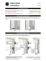
When shade is in the UP position,
fabric hangs over one end of
the shade and may interfere
with brackets
Telescoping fabric. Identify the direction of the overhang. Follow steps 1-3 of the battery
changing procedure to expose the shade tube. Apply a 3” x 3/4” piece
of masking tape horizontally on the shade tube on the side where fabric
overhangs tube. Press any button on the remote. Verify if the telescoping
has been corrected and repeat this process as needed.
Shade width is too narrow to hang
in brackets
Brackets too far apart. Measure shade fabric width. Adjust outside of bracket to outside of
bracket dimension to equal fabric width + 1”. Reinstall using shims to
level. Properly secure brackets.
Shade has fresh batteries and the
motor can be heard, but the shade is
moving slowly or not at all.
Shade and brackets
interfere with each other.
Remove the shade from the brackets and adjust the position and
mounting angle of the brackets to eliminate interference. Re-install the
shade.
Shade is unresponsive to a
specic button.
Stuck in a specic
position’s Learn Mode.
Wait 1 minute for the shade to automatically exit Learn Mode. All other
buttons except for this specic position’s button will work. However, while
in Down position Learn Mode, pressing the DOWN button will stop the
shade if moving up.
If you still experience difculties, please call toll-free 1-877-849-6070.
This device complies with Part 15 of the FCC Rules. Operation is subject to the following two conditions:
1) This device may not cause harmful interference, and
2) this device must accept any interference received, including interference that may cause undesired operation.
Warning: Changes or modications to this device not expressly approved by HomeRun Holdings could void the user’s authority to operate the
equipment.
“NOTE: This equipment has been tested and found to comply with the limits for a Class B digital device, pursuant to Part 15 of the FCC Rules. These
limits are designed to provide reasonable protection against harmful interference in a residential installation.
This equipment generates, uses, and can radiate radio frequency energy and, if not installed and used in accordance with the instructions, may cause
harmful interference to radio communications. However, there is no guarantee that interference will not occur in a particular installation. If this equipment
does cause harmful interference to radio or television reception, which can be determined by turning the equipment off and on, the user is encouraged to
try to correct the interference by one or more of the following measures: • Reorient or relocate the receiving antenna. • Increase the separation between
the equipment and receiver. • Connect the equipment into an outlet on a circuit different from that to which the receiver is connected. • Consult the dealer
or an experienced radio/TV technician for help.”
The term “IC:” before the radio certication number only signies that Industry Canada technical specications were met.
This Class B digital apparatus meets all requirements of the Canadian Interference Causing Equipment Regulations. Operation is subject to the following
two conditions:
(1) this device may not cause harmful interference, and (2) this device must accept any interference received, including interference that may cause
undesired operation.
Cet appareillage numérique de la classe B répond à toutes les exigences de l’interférence canadienne causant des règlements d’équipement.
L’opération est sujette aux deux conditions suivantes: (1) ce dispositif peut ne pas causer l’interférence nocive, et (2) ce dispositif doit accepter n’importe
quelle interférence reçue, y compris l’interférence qui peut causer l’opération peu désirée.
Do not operate at temperatures below 32° F or above 130° F. End user must ensure that shade being used is re resistant. Keep transmitter away
from children. Periodically examine assembly and brackets for signs of wear and discontinue use if repair is necessary. The controller and transmitter
assemblies contain no serviceable parts.
MODEL: HRH-WS02
WALL STATION TRANSMITTER
FCC ID: X6P-0003300
IC: 8832A-0003300
MODEL: HRH-PT05
PORTABLE TRANSMITTER
FCC ID: X6P-0003186B
IC: 8832A-0003186B
MODEL: QT-2
ROLLER SHADE
CAN RSS-GEN/CNR-GEN
MODEL: QTL74
QMOTION REMOTE
FCC ID: X6P-HR110845
IC: 8832A-HR110845
  • Page 1 1
  • Page 2 2
  • Page 3 3
  • Page 4 4
  • Page 5 5
  • Page 6 6
  • Page 7 7
  • Page 8 8

Legrand Qlink Brackets Installation guide

Type
Installation guide
This manual is also suitable for

Ask a question and I''ll find the answer in the document

Finding information in a document is now easier with AI