Page is loading ...

INST-898
B
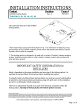
STANDARD TOP BAR
7170-0744-01
TOP BAR
LOWER
MOUTNING BRACKET
PUSH BUMPER
LIGHT BAR W/ WIRE COVER
7170-0744-02
LIGHT BAR
WIRE COVER
UPPER
MOUNTING BRACKET
PS-001
© Copyright 2019 Gamber-Johnson, LLC
1/6
These instructions cover the installation of the Gamber-Johnson push bumper on 2015 and
newer Chevrolet Tahoe. The push bumper can be purchased in the standard and light bar
configurations. In the standard configuration the push bumper features a bolt in round top
bar. In the light bar configuration the push bumper features a flat mounting bar for lights as
well as two wire chase covers for routing wires down the sides of the push bumper. Both
configurations feature the same push bumper as well as mounting brackets.
Printing Spec:
If you need assistance or have questions, call Gamber-Johnson at 1-800-456-6868
Form
Revision
Product
INSTALLATION INSTRUCTIONS
Product Mounting Disclaimer
Gamber-Johnson is not liable under any theory of contract or tort law for any loss, damage, personal injury, special, incidental or consequential damages for personal injury or other damage
of any nature arising directly or indirectly as a result of the improper installation or use of its products in vehicle or any other application. In order to safely install and use Gamber-Johnson
products full consideration of vehicle occupants, vehicle systems (i.e., the location of fuel lines, brake lines, electrical, drive train or other systems), air-bags and other safety equipment is
required. Gamber-Johnson specifically disclaims any responsibility for the improper use or installation of its products not consistent with original vehicle manufactures specifications
and recommendations, Gamber-Johnson product instruction sheets, or workmanship standards as endorsed through the Gamber-Johnson Certified Installer Program.
7170-0744-01 - STEEL STANDARD TOP BAR
7170-0744-02 - STEEL LIGHT BAR
PUSH BUMPER - CHEVROLET TAHOE 2015+

PUSH BUMPER INSTALL:
NOTE - For vehicle equipped without OEM tow hook package see Step 1, for vehicles
equipped with OEM tow hook see Step 2.
1.
For vehicles without the OEM tow hook may need to remove the lower front mold
and make an opening for the vehicle frame. (see below, then continue to step 3. )
Lower front mold
Note: Create a square cut out (5 inches wide X height of mold ) 14 inches from
center of the vehicle (
Check Alignment with vehicle before cutting
).
*vehicle mold piece may have indent lines can be used as a guide for cutting,
double check before cutting.
2.
For vehicles with OEM tow hooks remove the
tow hooks with 18mm socket and wrench.
3.
Attach the driver side bracket by sliding
through the tow hook openning in the front
bumper and into the vehicle frame.
4.
Attach the push bumper bracket to the frame
with hardware 3/8 thick washer - 3/8 lock washer
- 3/8-16 G8 bolts. repeat for the passanger side.
*hand tight the bolts for now
5.
To install the upper brackets, in the engine bay first remove the front
engine shroud. to remove the plastic push-in clips use a clip tool or a
flat head screwdriver insert into top of the clip and pull up slowly.
2/6

6.
After removing the plastic shroud, then using a 10mm socket and ratchet remove
the 6 bolts hold the grille.
7.
After removing the bolts, pull on the grille carfully (grille is held
in by clips
(marked in yellow arrow, grille will tilt forward, will not come off)
to gain
space to insert the upper brrackets.
8.
In the grille cut away an opening as shown marked
with blue arrow. Repeat for driver side as well.
*you may need to remove more material
for easier install.
9.
Rmove the bolt with a 10MM socket, then feed
the upper brackets through the new openning in
the grille for both side and attch to vehicle with factory
hardware. push grille back in place with clips and
secure with factory bolts.
3/6

S
S
S
S
P
P
P
P
10.
With bracket inplace then attach the push bumper to the brackets with 3/8-
16 G8 bolts - 3/8 washer - 3/8 lock washer - 3/8-16 G8 nut. with everything
aligned torqe down the hardware and check if anything is loose.
Bumper Adjustment Feature:
With Gamber-Johnson Push Bumpers it has a build in Adjustment feature to locate
the push bumper in Standard or Push position. In the "Push position" the bumper
will be located farther from the vehicle to reduce damage during use.
*if customer has the upper bar option, the upper bar and bracket will share
hardware.
Position Locator:
Push : bolt pattern will be marked "P"
Standard: bolt pattern will be marked "S"
4/6

Top Bar
3/8-16 G8 bolt
3/8-16 G8 Nut
3/8 Lock Washer
Light Bar
1/4-20 Bolt
1/4 Washer
Wire Chase
Cover
#10 Machine Screw
#10 Washer
To Install Round Top Bar:
1. Bolt the round upper bar in place using the 3/8-16 x 1.00 bolts, lock washers and nuts
provided.
To Install Light Bar:
1. After the lights have been installed in the light bar, align the light bar and rear cover with
the top holes in the push bumper. Wires can be guided through the notches at either end of
the light bar. Install the light bar and cover using the 1/4-20 x 1.00 bolts and washers
provided.
2. The side wire chase covers can be installed to guide wires down from the light bar to the
flat plate in the middle of the push bumper. The covers are installed using #10-32 x 0.500
machine screws and #10 washers. The edges of the cover may need to be tucked
underneath the flexible rubber strip on the front of the push bumper to be installed.
5/6

5.24
4.11
2.37
1.23
To Install Lights on Bar:
Knock out the two knockouts that line up with the mouting holes of chosen light. Bolt light
1.
onto bar per light instructions.
Acceptable Lights:
The light bar knockouts are designed for the following light models:
1.
6/6
/