American Standard T018.500.278 Installation guide

Category
Sanitary ware
Type
Installation guide

This manual is also suitable for

- 1 -
Product names listed herein are trademarks of AS America, Inc.
© AS America, Inc. 2017
Thank you for selecting American Standard...
the benchmark of fine quality for over 100 years.
To ensure that your installation proceeds smoothly-please
read these instructions carefully before you begin.
RECOMMENDED TOOLS
M965807 Rev. 1.1 (10/19)
ROUGHING-IN DIMENSIONS
EDGEMERE
TUB AND SHOWER
INSTALLATION
INSTRUCTIONS
T018.50X
Plumbers’ Putty
or Caulking
Adjustable Wrench Channel Locks
Phillips Screwdriver
Certied to comply with ANSI A112.18.1M
To assure proper positioning in relation to wall.
Note roughing-in dimensions.
C
H
OFF
Teon Tape
Flat Blade Screwdriver
THREADED INLETS (STOPS)
INLETS
1/2" NPT
5-7/8"
(149 mm)
5-7/8"
(149 mm)
5-7/8"
(149 mm)
INLETS 1/2" NPT
OUTLETS
1/2" NPT
OUTLETS
1/2" NPT
3-3/8"
(86 mm)
3-3/8"
(86 mm)
THREADED INLETS
SHR. 1/2" NOM.
COPPER SWEAT
TUB 1/2" NOM.
COPPER SWEAT
4-1/16" (103 mm)
INLETS
4-1/16"
(103 mm)
4-1/16"
(103 mm)
INLETS
1/2" NOM.
COPPER
SWEAT
SHR. 1/2" NOM.
COPPER SWEAT
TUB 1/2" NOM.
COPPER SWEAT
2"
SWEAT
INLETS
SWEAT
INLETS (STOPS)
INLETS
1/2" NOM.
COPPER
SWEAT
1/2" COPPER
FOR SLIP-ON
SPOUT
7-11/16"
(195 mm)
1-5/8" to 3-1/4"
1/2" (13 mm) I.P.S.
FINISHED FLOOR USUALLY
BETWEEN 65" AND 78"
(1651 AND 1981MM)
FINISHED WALL
18" (457 mm)
OPTIONAL
TOP OF TUB RIM
*5-1/8" (130 mm) Ref.
4"
(102 mm)
1-1/2"
2-3/4" MAX. (69 mm)
1-3/4" MIN. (45 mm)
- 2 -
C
H
OFF
Figure 1.
Figure 2.
2
PLASTER
GUARD
1
4
5
1
3
6
1
M965807 Rev. 1.1 (10/19)
Figure 1. Remove plaster guard from valve. Push
CAP (1) over VALVE CARTRIDGE (2) until seated
against stop.
Figure 2. Push ESCUTCHEON (3) onto CAP (1) and
attach to valve body with LONG SCREWS (4). Mount
DECORATIVE PLATE (5) to ESCUTCHEON (3) by
aligning three PINS (6) on back side of DECORATIVE
PLATE (5).
INSTALL VALVE TRIM
2
INSTALL TUB SPOUT, SHOWER HEAD,
SHOWER ARM WITH FLANGE
Remove pipe cap and plug from shower and tub
rough piping.
Slip DECORATIVE PLATE (5), then slip TUB SPOUT (1)
onto tub nipple and tighten with 2.5 mm Hex Wrench.
CAUTION: Protect finish on TUB SPOUT when
installing.
Install SHOWER ESCUTCHEON (2) onto SHOWER
ARM (3). Apply sealant or Teon tape to threads on
both ends of SHOWER ARM (3) and thread longer
leg of SHOWER ARM (3) into shower elbow.
Thread SHOWER HEAD (4) onto SHOWER ARM (3).
CAUTION: Protect finish on SHOWER HEAD and
ARM when installing.
CAUTION
Protect finish on SHOWER HEAD
and TUB SPOUT when installing.
C
H
OFF
PIPE
PLUG
PIPE
CAP
4
3
2
SHR.
ELBOW
TUB FILLER
NIPPLE
1-1/2" REF.
2.5 MM HEX
WRENCH
1
5
- 3 -
4
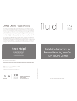
HOT LIMIT SAFETY STOP ADJUSTMENT
By restricting HANDLE rotation and limiting the
amount of hot water allowed to mix with the cold,
the HOT LIMIT STOP (1) reduces risk of accidental
scalding. To set the maximum hot water temperature
of your faucet, all you need to do is adjust the setting
on the HOT LIMIT STOP (1).
Turn CARTRIDGE STEM (2) to the OFF position
(coldest setting) before making adjustment to HOT
LIMIT STOP (1). Use a at blade screwdriver to pry
free the HOT LIMIT STOP (1). Pull forward and rotate
counterclockwise to limit hot water temperature.
Use ARROW (3) on CARTRIDGE (4) and NUMBERS (5)
on HOT LIMIT STOP (1) for indication.
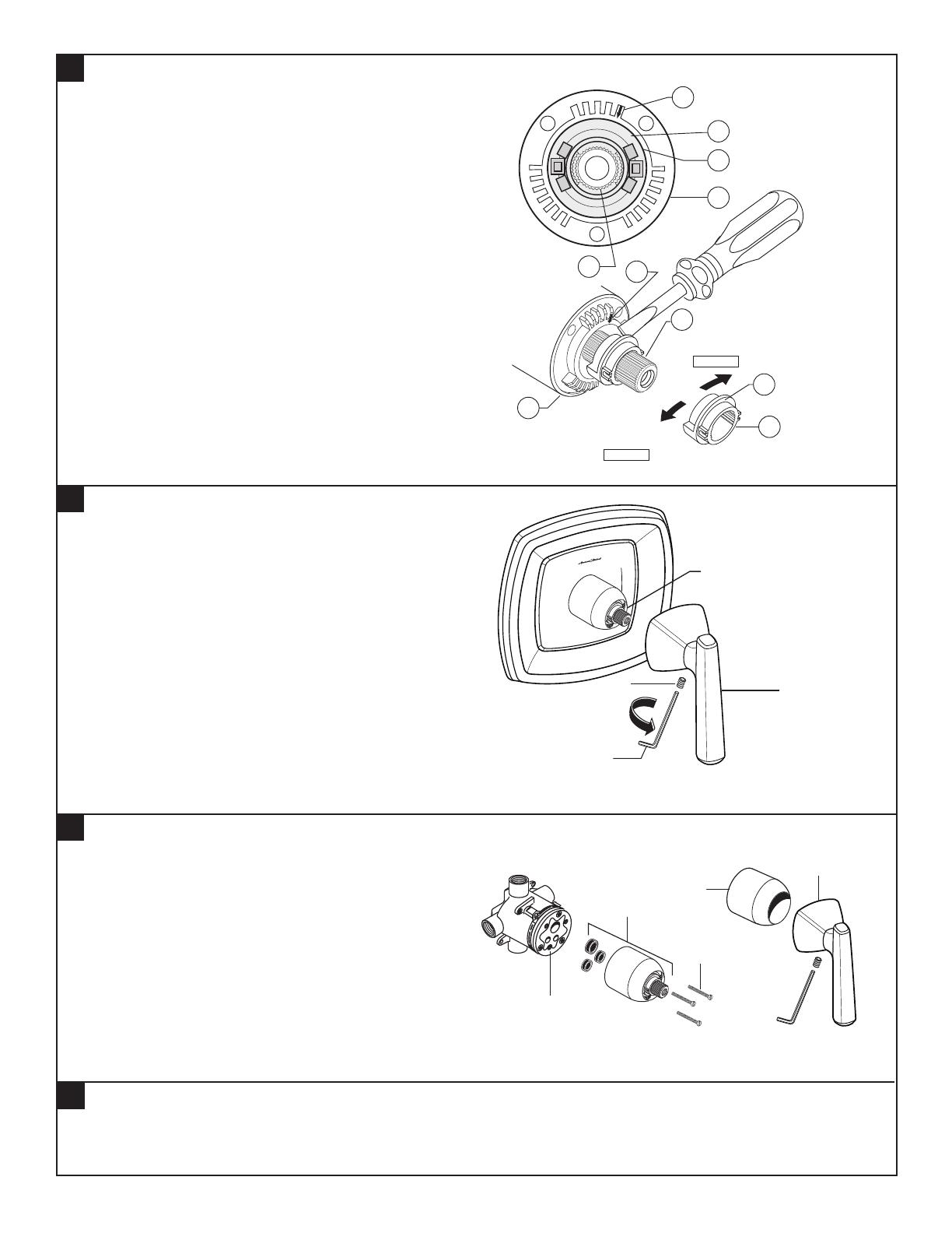
Install HANDLE (1) by pushing it onto CARTRIDGE STEM (2)
and tightening SET SCREW (3) from below with 2.5 mm
Hex Wrench supplied.
HANDLE INSTALLATION
ADJUST HOT LIMIT STOP
3
M965807 Rev. 1.1 (10/19)
6
CARE INSTRUCTIONS:
DO: SIMPLY RINSE THE PRODUCT CLEAN WITH CLEAR WATER. DRY WITH A SOFT COTTON FLANNEL CLOTH.
DO NOT: DO NOT CLEAN THE PRODUCT WITH SOAPS, ACID, POLISH, ABRASIVES, HARSH CLEANERS, OR A
CLOTH WITH A COARSE SURFACE.
C
H
OFF
1
2.5MM HEX
WRENCH
3
2
5
If faucet drips, operate handle several times from “off”
to “on”. Do not apply excessive force.
Clogged CARTRIDGE (4) inlets may cause reduced ow
in “full on” hot or cold. To clean inlets, rst turn off water
supply, then:
– Remove HANDLE (1), CAP (2) and CARTRIDGE (4).
Clean inlets and MANIFOLD (5).
– Reassemble CARTRIDGE (4), alternately tightening
SCREWS (3).
– Replace CAP (2) and HANDLE (1). Check ow.
SERVICE
5
4
3
2
1
1
5
1
3
1
1
9
7
5
3
1
0
1
5
1
3
1
1
9
7
5
3
1
1
5
1
3
1
1
9
7
5
3
1
COLDER
(Larger Numbers)
MÁS FRÍA
(números mayores)
0 1 3 5 7 9 11 13 15
HOTTER
(Smaller Numbers)
MÁS CALIENTE
(números menores)
0 1 3 5 7 9 11 13 15
1
5
1
5
4
4
3
3
2
2
- 4 -- 4 -
M965807 Rev. 1.1 (10/19)
HOT LINE FOR HELP
For toll-free information and answers to your questions, call:
1 (800) 442-1902
Mon. - Fri. 8:00 a.m. to 8:00 p.m. EST
Saturday 10:00 a.m. to 4:00 p.m. EST
IN CANADA 1-800-387-0369
(TORONTO 1-905-306-1093)
Weekdays 8:00 a.m. to 7:00 p.m. EST
IN MEXICO 01-800-839-1200
M970410-0070A
Cartridge
C
H
OFF
M970579-0070A
Screw & Adapter Kit
M970138-YYY0A
Shower Arm & Flange
M970139-YYY0A
Decorative Plate
M970145-002250A
Shower Head (2.5 gpm)
M970145-002180A
Shower Head (1.8 gpm)
M970448-YYY0A
Escutcheon & Screws
M907051-YYY0A
Cover
M970353-YYY0A
Diverter Spout (Slip-on)
M970057-YYY0A
Lever Handle Kit
M970114-YYY0A
Set Screw & Button Kit
NOTE: TO AVOID SHOWER RISE OR OTHER RELATED ISSUES,
DO NOT USE PEX CONNECTIONS ON ANY OF THE OUTLETS.
M954805-YYY0A
Deep Rough-in Kit
PURCHASE SEPARATELY
PURCHASE SEPARATELY
M970640-0070A
Back-to-Back
Cartridge
EDGEMERE
TUB AND SHOWER
MODEL NUMBER
T018.50X
Replace the “YYY” with
appropriate finish code
CHROME 002
BRUSHED NICKEL 295
LEGACY BRONZE 278
1 / 1

American Standard T018.500.278 Installation guide

Category
Sanitary ware
Type
Installation guide
This manual is also suitable for

Ask a question and I''ll find the answer in the document

Finding information in a document is now easier with AI

Ask the document