Page is loading ...

SERVICE MANUAL
Spreader/Sprayer
Residential Products
Issued: May 2016

Table of Contents
ABOUT THIS MANUAL
2016 The Toro Company
All Rights Reserved
This service manual was written expressly for Toro service technicians. The Toro Company has made every effort
to make the information in this manual complete and correct.
Basic shop safety knowledge and mechanical/electrical skills are assumed. The Table of Contents lists the
systems and the related topics covered in this manual.
The Spreader/Sprayer is covered in this manual. The manual may also be specied for use on later model
products.
Due to the compact design, parts were removed for photographic purposes when necessary.
We are hopeful that you will nd this manual a valuable addition to your service shop. If you have any questions
or comments regarding this manual, please contact us at the following address:
The Toro Company
Residential Contractor Service Training Department
8111 Lyndale Avenue South
Bloomington, MN 55420
The Toro Company reserves the right to change product specications on this manual without notice.

2 Table of Contents
TABLE OF CONTENTS
1. Safety
General Safety Information........................................................................................................................
2. Specications and Maintenance
Torque Specications.................................................................................................................................
Standard Torque (Inch Series)...................................................................................................................
Standard Torque (Metric Fasteners)..........................................................................................................
Other Torque Specications......................................................................................................................
Equivalents and Conversions....................................................................................................................
U.S. to Metric Conversions.........................................................................................................................
Recommended Maintenance Schedule.....................................................................................................
Premaintenance Procedures.....................................................................................................................
Lubrication...................................................................................................................................................
Engine Maintenance....................................................................................................................................
Electrical System Maintenance..................................................................................................................
Drive System Maintenance.........................................................................................................................
Controls System Maintenance...................................................................................................................
Maintaining the Sprayer System................................................................................................................
Cleaning.......................................................................................................................................................
Storage.........................................................................................................................................................
3. Spreader System
Spreader Subsystem Diagram...................................................................................................................
Spreader Bottom Section View Diagram..................................................................................................
Spreader Controls and Console View Diagram........................................................................................
Spreader Left Rear View Diagram..............................................................................................................
Spreader Right Side View Diagram...........................................................................................................
Hopper Spreader Asm. Diagram................................................................................................................
Hopper Replacement..................................................................................................................................
Removal...................................................................................................................................................
Installation...............................................................................................................................................
4. Chassis
Steering Subsystem Diagram....................................................................................................................
Frame Subsystem Diagram........................................................................................................................
Front Axle Assembly Replacement...........................................................................................................
Removal...................................................................................................................................................
Installation...............................................................................................................................................
Control Tower Replacement......................................................................................................................
Removal...................................................................................................................................................
Installation...............................................................................................................................................
5. Engine
Engine Subsystem......................................................................................................................................
Engine Replacement...................................................................................................................................
Removal...................................................................................................................................................
Installation...............................................................................................................................................
1-1
2-1
2-2
2-3
2-4
2-5
2-6
2-7
2-8
2-8
2-9
2-15
2-19
2-21
2-22
2-22
2-23
3-1
3-2
3-3
3-4
3-5
3-6
3-7
3-7
3-8
4-1
4-2
4-3
4-3
4-4
4-6
4-6
4-7
5-1
5-2
5-2
5-4

3Table of Contents
6. Sprayer System
Spray Subsystem 1 Diagram......................................................................................................................
Manifold-Valve Control Diagram................................................................................................................
Spray System Fitting Orientation Diagram...............................................................................................
Spray System Left Front View Diagram....................................................................................................
Spray System Rear View (Under Console) Diagram................................................................................
Spray System Right Rear View Diagram...................................................................................................
Valve Block Replacement...........................................................................................................................
Removal...................................................................................................................................................
Installation...............................................................................................................................................
Electrical Schematic...................................................................................................................................
7. Electrical
Electrical Subsystem Diagram...................................................................................................................
Electrical View Left Inside..........................................................................................................................
Electrical View Right Inside.......................................................................................................................
Electrical View Under Console..................................................................................................................
Electrical Schematic...................................................................................................................................
8. Drive System
Ground Drive Subsystem...........................................................................................................................
Transmission Replacement........................................................................................................................
Removal...................................................................................................................................................
Installation...............................................................................................................................................
6-1
6-2
6-3
6-4
6-5
6-6
6-7
6-7
6-8
6-10
7-1
7-2
7-3
7-4
7-5
8-1
8-2
8-2
8-4

Toro®- Spreader/Sprayer Service Manual 1-1Table of Contents
SAFETY
1
General Information
This symbol means WARNING or PERSONAL SAFETY
INSTRUCTION - read the instruction be-
cause if has to do with your safety. Failure
to comply with the instruction may result in
personal injury or even death.
This manual is intended as a service and
repair manual only. The safety instructions provided
herein are for troubleshooting, service, and repair of the
Toro Spreader/Sprayer. The Spreader/Sprayer and oper-
ator’s manual contains safety information and operating
tips for safe operating practices. Operator’s manuals are
available through your Toro parts source or:
The Toro Company
Publications Department
8111 Lyndale Avenue South
Bloomington, MN 55420
Think Safety First
Avoid injury due to inferior parts...
Use only original equipment parts to ensure that import-
ant safety criteria are met.
Avoid injury to bystanders...
Always clear the area of bystanders before starting or
testing powered equipment.
Avoid injury due to projectiles...
Always clear the area of sticks, rocks, or any other de-
bris that could be picked up and thrown by the powered
equipment.
Avoid modications...
Never alter or modify any part unless it is a factory ap-
proved procedure.
Avoid unsafe operation...
Always test the safety interlock system after making
adjustments or repairs on the machine. Refer to the
Electrical section in this manual for more information.
Avoid unexpected starting of engine...
Always turn off the engine and disconnect the spark plug
wire(s) before cleaning, adjusting, or repair.
Avoid lacerations and amputations...
Stay clear of all moving parts whenever the engine is
running. Treat all normally moving parts as if they were
moving whenever the engine is running or has the po-
tential to start.
Avoid burns...
Do not touch the engine, mufer, or other components
which may increase in temperature during operation,
while the unit is running or shortly after it has been run-
ning.
Avoid res and explosions...
Avoid spilling fuel and never smoke while working with
any type of fuel or lubricant. Wipe up any spilled fuel
or oil immediately. Never remove the fuel cap or add
fuel when the engine is running. Always use approved,
labeled containers for storing or transporting fuel and
lubricants.
Avoid asphyxiation...
Never operate an engine in a conned area without
proper ventilation.
Avoid injury from batteries...
Battery acid is poisonous and can cause burns. Avoid
contact with skin, eyes, and clothing. Battery gases can
explode. Keep cigarettes, sparks, and ames away from
the battery.
!

Toro®- Spreader/Sprayer Service Manual Table of Contents
SPECIFICATIONS AND MAINTENANCE
2-1
2
SPECIFICATIONS
2 - 4 TimeCutter
®
Z Service Manual
Torque Specifications
Recommended fastener torque values are listed in the
following tables. For critical applications, as
determined by Toro, either the recommended torque or
a torque that is unique to the application is clearly
identified and specified in the service manual.
These torque specifications for the installation and
tightening of fasteners shall apply to all fasteners which
do not have a specific requirement identified in the
service manual. The following factors shall be
considered when applying torque: cleanliness of the
fastener, use of a thread sealant (Loctite), degree of
lubrication on the fastener, presence of a prevailing
torque feature, hardness of the surface underneath of
the fastener’s head, or similar condition which affects
the installation.
As noted in the following tables, torque values should
be reduced by 25% for lubricated fasteners to
achieve the similar stress as a dry fastener. Torque
values may also have to be reduced when the fastener
is threaded into aluminum or brass. The specific
torque value should be determined based on the
aluminum or brass material strength, fastener size,
length of thread engagement, etc.
The standard method of verifying torque shall be
performed by marking a line on the fastener (head or
nut) and mating part, then back off fastener 1/4 of a
turn. Measure the torque required to tighten the
fastener until the lines match up.
Fastener Identification
Figure 1
Figure 2
Inch Series Bolts and Screws
(A) Grade 1
(B) Grade 5
(C) Grade 8
Metric Bolts and Screws
(A) Class 8.8 (B) Class 10.9
2
Torque Specications

Toro®- Spreader/Sprayer Service Manual
2
Table of Contents
SPECIFICATIONS AND MAINTENANCE
2-2
SPECIFICATIONS
TimeCutter
®
Z Service Manual 2 - 5
Standard Torque for Dry, Zinc Plated, and Steel Fasteners (Inch Series)
Note: Reduce torque values listed in the table above
by 25% for lubricated fasteners. Lubricated fasteners
are defined as threads coated with a lubricant such as
oil, graphite, or thread sealant such as Loctite.
Note: Torque values may have to be reduced when
installing fasteners into threaded aluminum or brass.
The specific torque value should be determined based
on the fastener size, the aluminum or base material
strength, length of thread engagement, etc.
Note: The nominal torque values listed above for
Grade 5 and 8 fasteners are based on 75% of the
minimum proof load specified in SAE J429. The
tolerance is approximately ± 10% of the nominal
torque value. Thin height nuts include jam nuts.
Thread Size
Grade 1, 5, &
8 with Thin
Height Nuts
SAE Grade 1 Bolts, Screws,
Studs, & Sems with Regular
Height Nuts (SAE J995
Grade 2 or Stronger Nuts)
SAE Grade 5 Bolts, Screws,
Studs, & Sems with Regular
Height Nuts (SAE J995
Grade 2 or Stronger Nuts)
SAE Grade 8 Bolts, Screws,
Studs, & Sems with Regular
Height Nuts (SAE J995
Grade 2 or Stronger Nuts)
In-lb In-lb N-cm In-lb N-cm In-lb N-cm
# 6 - 32 UNC
10 ± 2 13 ± 2 147 ± 23
15 ± 2 170 ± 20 23 ± 2 260 ± 20
# 6 - 40 UNF 17 ± 2 190 ± 20 25 ± 2 280 ± 20
# 8 - 32 UNC
13 ± 2 25 ± 5 282 ± 30
29 ± 3 330 ± 30 41 ± 4 460 ± 45
# 8 - 36 UNF 31 ± 3 350 ± 30 43 ± 4 31 ± 3
# 10 - 24 UNC
18 ± 2 30 ± 5 339 ± 56
42 ± 4 475 ± 45 60 ± 6 674 ± 70
#10 - 32 UNF 48 ± 4 540 ± 45 68 ± 6 765 ± 70
1/4 - 20 UNC 48 ± 7 53 ± 7 599 ± 79 100 ± 10 1125 ± 100 140 ± 15 1580 ± 170
1/4 - 28 UNF 53 ± 7 65 ± 10 734 ± 113 115 ± 10 1300 ± 100 160 ± 15 1800 ± 170
5/16 - 18 UNC 115 ± 15 105 ± 17 1186 ± 169 200 ± 25 2250 ± 280 300 ± 30 3390 ± 340
5/16 - 24 UNF 138 ± 17 128 ± 17 1446 ± 192 225 ± 25 2540 ± 280 325 ± 30 3670 ± 340
ft-lb ft-lb N-m ft-lb N-m ft-lb N-m
3/8 - 16 UNC 16 ± 2 16 ± 2 22 ± 3 30 ± 3 41 ± 4 43 ± 4 58 ± 5
3/8 - 24 UNF 17 ± 2 18 ± 2 24 ± 3 35 ± 3 47 ± 4 50 ± 4 68 ± 5
7/16 - 14 UNC 27 ± 3 27 ± 3 37 ± 4 50 ± 5 68 ± 7 70 ± 7 68 ± 9
7/16 - 20 UNF 29 ± 3 29 ± 3 39 ± 4 55 ± 5 75 ± 7 77 ± 7 104 ± 9
1/2 - 13 UNC 30 ± 3 48 ± 7 65 ± 9 75 ± 8 102 ± 11 105 ± 10 142 ± 14
1/2 - 20 UNF 32 ± 3 53 ± 7 72 ± 9 85 ± 8 115 ± 11 120 ± 10 163 ± 14
5/8 - 11 UNC 65 ± 10 88 ± 12 119 ± 16 150 ± 15 203 ± 20 210 ± 20 285 ± 27
5/8 - 18 UNF 75 ± 10 95 ± 15 129 ± 20 170 ± 15 230 ± 20 240 ± 20 325 ± 27
3/4 - 10 UNC 93 ± 12 140 ± 20 190 ± 27 265 ± 25 359 ± 34 374 ± 35 508 ± 47
3/4 - 16 UNF 115 ± 15 165 ± 25 224 ± 34 300 ± 25 407 ± 34 420 ± 35 569 ± 47
7/8 - 9 UNC 140 ± 20 225 ± 25 305 ± 34 430 ± 45 583 ± 61 600 ± 60 813 ± 81
7/8 - 14 UNF 155 ± 25 260 ± 30 353 ± 41 475 ± 45 644 ± 61 660 ± 60 895 ± 81

Toro®- Spreader/Sprayer Service Manual Table of Contents
SPECIFICATIONS AND MAINTENANCE
2-3
2
SPECIFICATIONS
2 - 6 TimeCutter
®
Z Service Manual
Standard Torque for Dry, Zinc, and Steel Fasteners (Metric Fasteners)
Note: Reduce torque values listed in the table above
by 25% for lubricated fasteners. Lubricated fasteners
are defined as threads coated with a lubricant such as
oil, graphite, or thread sealant such as Loctite.
Note: Torque values may have to be reduced when
installing fasteners into threaded aluminum or brass.
The specific torque value should be determined based
on the fastener size, the aluminum or base material
strength, length of thread engagement, etc.
Note: The nominal torque values listed above are
based on 75% of the minimum proof load specified in
SAE J1199. The tolerance is approximately ± 10% of
the nominal torque value. Thin height nuts include jam
nuts.
Thread Size
Class 8.8 Bolts, Screws, and Studs with
Regular Height Nuts
(Class 8 or Strong Nuts)
Class 10.9 Bolts, Screws, and Studs with
Regular Height Nuts (
Class 10 or Strong Nuts)
M5 X 0.8 57 ± 5 in-lb 640 ± 60 N-cm 78 ± 7 in-lb 885 ± 80 N-cm
M6 X 1.0 96 ± 9 in-lb 1018 ± 100 N-cm 133 ± 13 in-lb 1500 ± 150 N-cm
M8 X 1.25 19 ± 2 ft-lb 26 ± 3 N-m 27 ± 2 ft-lb 36 ± 3 N-m
M10 X 1.5 38 ± 4 ft-lb 52 ± 5 N-m 53 ± 5 ft-lb 72 ± 7 N-m
M12 X 1.75 66 ± 7 ft-lb 90 ± 10 N-m 92 ± 9 ft-lb 125 ± 12 N-m
M16 X 2.0 166 ± 15 ft-lb 225 ± 20 N-m 229 ± 22 ft-lb 310 ± 30 N-m
M20 X 2.5 325 ± 33 ft-lb 440 ± 45 N-m 450 ± 37 ft-lb 610 ± 50 N-m

Toro®- Spreader/Sprayer Service Manual
2
Table of Contents
SPECIFICATIONS AND MAINTENANCE
2-4
SPECIFICATIONS
TimeCutter
®
Z Service Manual 2 - 7
Other Torque Specifications
SAE Grade 8 Steel Set Screws
Thread Cutting Screws
(Zinc Plated Steel)
Conversion Factors
in-lb X 11.2985 - N-cm
ft-lb X 1.3558 = N-m
Wheel Bolts and Lug Nuts
** For steel wheels and non-lubricated fasteners.
Thread Cutting Screws
(Zinc Plated Steel)
* Hole size, material strength, material thickness and
finish must be considered when determining specific
torque values. All torque values are based on non-
lubricated fasteners.
N-cm X - 0.08851 = in-lb
N-cm X 0.73776 - ft-lb
Thread Size
Recommended Torque
Square Head Hex Socket
1/4 - 20 UNC 140 ± 20 in-lb 73 ± 12 in-lb
5/16 - 18 UNC 215 ± 35 in-lb 145 ± 20 in-lb
3/8 - 16 UNC 35 ± 10 ft-lb 18 ± 3 ft-lb
1/2 - 13 UNC 75 ± 15 ft-lb 50 ± 10 ft-lb
Type 1, Type 23, or Type F
Thread Size Baseline Torque*
No. 6 - 32 UNC 20 ± 5 in-lb
No. 8 - 32 UNC 30 ± 5 in-lb
No.10 - 24 UNC 38 ± 7 in-lb
1/4 - 20 UNC 85 ± 15 in-lb
5/16 - 18 UNC 110 ± 20 in-lb
3/8 - 16 UNC 200 ± 100 in-lb
Thread Size Recommended Torque**
7/16 - 20 UNF
Grade 5
65 ± 10 ft-lb 88 ± 14 N-m
1/2 - 20 UNF
Grade 5
80 ± 10 ft-lb 108 ± 14 N-m
M12 X 1.25
Class 8.8
80 ± 10 ft-lb 108 ± 14 N-m
M12 X 1.5
Class 8.8
80 ± 10 ft-lb 108 ± 14 N-m
Thread
Size
Threads per Inch
Baseline Torque*
Type A Type B
No. 6 18 20 20 ± 5 in-lb
No. 8 15 18 30 ± 5 in-lb
No. 10 12 16 38 ± 7 in-lb
No. 12 11 14 85 ± 15 in-lb

Toro®- Spreader/Sprayer Service Manual Table of Contents
SPECIFICATIONS AND MAINTENANCE
2-5
2
SPECIFICATIONS
2 - 8 TimeCutter
®
Z Service Manual
Equivalents and Conversions
Decimal and Millimeter Equivalents
Fractions Decimals mm Fractions Decimals mm
1/64 0.015625 0.397 33/64 0.515625 13.097
1/32 0.03125 0.794 16/32 0.53125 13.484
3/64 0.046875 1.191 35/64 0.546875 13.891
1/16 0.0625 1.588 9/16 0.5625 14.288
5/64 0.078125 1.984 37/64 0.578125 14.684
3/32 0.9375 2.381 19/32 0.59375 15.081
1/8 0.1250 3.175 5/8 0.6250 15.875
9/64 0.140625 3.572 41/64 0.640625 16.272
5/32 0.15625 3.969 21/32 0.65625 16.669
11/64 0.171875 4.366 43/64 0.671875 17.066
3/16 0.1875 4.762 11/16 0.6875 17.462
13/64 0.203125 5.159 45/64 0.703125 17.859
7/32 0.21875 5.556 23/32 0.71875 18.256
15/64 0.234375 5.953 47/64 0.734375 18.653
1/4 0.2500 6.350 3/4 0.7500 19.050
17/64 0.265625 6.747 49/64 0.765625 19.447
9/32 0.28125 7.144 25/32 0.78125 19.844
19/64 0.296875 7.541 51/64 0.796875 20.241
5/16 0.3125 7.541 13/16 0.8125 20.638
21/64 0.328125 8.334 53/64 0.828125 21.034
11/32 0.34375 8.731 27/32 0.84375 21.431
23/64 0.359375 9.128 55/64 0.859375 21.828
3/8 0.3750 9.525 7/8 0.8750 22.225
25/64 0.390625 9.922 57/64 0.890625 22.622
13/32 0.40625 10.319 29/32 0.90625 23.019
27/64 0.421875 10.716 59/64 0.921875 23.416
7/16 0.4375 11.112 15/16 0.9375 23.812
29/64 0.453125 11.509 61/64 0.953125 24.209
15/32 0.46875 11.906 31/32 0.96875 24.606
31/64 0.484375 12.303 63/64 0.984375 25.003
1/2 0.5000 12.700 1 1.000 25.400
1 mm = 0.03937 in. 0.001 in. = 0.0254 mm

Toro®- Spreader/Sprayer Service Manual
2
Table of Contents
SPECIFICATIONS AND MAINTENANCE
2-6
SPECIFICATIONS
TimeCutter
®
Z Service Manual 2 - 9
U.S. to Metric Conversions
To Convert Into Multiply By
Linear
Measurement
Miles
Yards
Feet
Feet
Inches
Inches
Inches
Kilometers
Meters
Meters
Centimeters
Meters
Centimeters
Millimeters
1.609
0.9144
0.3048
30.48
0.0254
2.54
25.4
Area
Square Miles
Square Feet
Square Inches
Acre
Square Kilometers
Square Meters
Square Centimeters
Hectare
2.59
0.0929
6.452
0.4047
Volume
Cubic Yards
Cubic Feet
Cubic Inches
Cubic Meters
Cubic Meters
Cubic Centimeters
0.7646
0.02832
16.39
Weight
Tons (Short)
Pounds
Ounces
Metric Tons
Kilograms
Grams
0.9078
0.4536
28.3495
Pressure
Pounds/Sq. In. Kilopascal
6.895
Work
Foot-pounds
Foot-pounds
Inch-pounds
Newton-Meters
Kilogram-Meters
Kilogram-Centimeters
1.356
0.1383
1.152144
Liquid Volume
Quarts
Gallons
Liters
Liters
0.9463
3.785
Liquid Flows
Gallons/Minute Liters/Minute
3.785
Temperature
Fahrenheit Celsius
1. Subtract 32°
2. Multiply by 5/9

Toro®- Spreader/Sprayer Service Manual Table of Contents
SPECIFICATIONS AND MAINTENANCE
2-7
2
Maintenance
WARNING
While you are maintaining or adjusting the machine,
someone could start the engine. Accidentally starting
the engine could seriously injure you or other
bystanders.
Remove the key from the ignition switch, engage
parking brake, and pull the wire(s) off the spark plug(s)
before you do any maintenance. Also push the wire(s)
aside so it does not accidentally contact the spark
plug(s).
WARNING
The engine can become very hot. Touching a hot
engine can cause severe burns.
Allow the engine to cool completely before service or
making repairs around the engine area.
Recommended Maintenance Schedule(s)
Maintenance Service
Interval
Maintenance Procedure
Before each use or daily
• Check the engine-oil level.
• Check the safety interlock system.
• Test the starter interlock.
• Check the machine for loose hardware.
• Check air cleaner; replace if dirty (may need more often under severe conditions).
• Clean the engine and the exhaust system area.
• Clean the grass and debris buildup from the machine.
After each use
• Clean and lubricate the spreader.
• Clean the sprayer tank.
• Clean the strainer.
• Clean the sprayer nozzles.
Every 50 hours
• Clean the foam air-cleaner element (more often under severe conditions).
• Check the pressure in the tires.
• Service the transaxle.
• Check sprayer system.
Every 80 hours
• Remove the engine shrouds and clean the cooling ns.
Every 100 hours
• Lubricate the grease ttings.
• Replace the dual element air lter.
• Change the engine oil.
• Change the engine oil (more often under severe condition).
• Check, clean and gap the spark plug.
Every 200 hours
• Service the spark arrester.
Monthly
• Clean the fuel sediment cup.
• Service the fuel strainer.
• Check the battery.
Yearly
• Torque the axle bolts.
Yearly or before storage
• Prepare the machine for storage.
50

Toro®- Spreader/Sprayer Service Manual
2
Table of Contents
SPECIFICATIONS AND MAINTENANCE
2-8
Premaintenance
Procedures
CAUTION
Raising the machine for service or maintenance
relying solely on mechanical or hydraulic jacks could
be dangerous. The mechanical or hydraulic jacks may
not be enough support or may malfunction allowing
the machine to fall, which could cause injury.
Do not rely solely on mechanical or hydraulic jacks for
support. Use adequate jack stands or equivalent
support.
Preparing Machine for
Maintenance
Perform the following before servicing, cleaning, or making
any adjustments to the machine.
1. Move the machine to a level surface.
2. Shut off the engine, set the parking brake, wait for
all moving parts to stop.
3. Remove the key from the key switch.
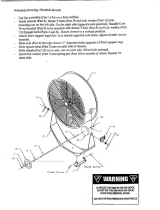
Lubrication
Lubricating the Grease Fittings
Service Interval: Every 100 hours
Grease type: National Lubricating Grease Institute (NGLI)
grade #2 multi-purpose gun grease.
Note: Refer to the lubrication chart for the grease
points and service intervals.
Lubrication Chart
Fitting Locations Initial Pumps
Number of
Places
1. Wheel bearings 1to2 2
2. Kingpin pivots 1to2 2
3. Front axle pivots 1to2 1
4. Steering control
pivot
1to2 1
Figure 1
1. Stop engine, set the parking brake, wait for all
moving parts to stop, and remove key.
2. Wipe clean the grease fittings with a rag (Figure 1).
3. Connect a grease gun to the fitting (Figure 1).
4. Pump grease into the fittings until grease begins to
ooze out of the bearings.
5. Wipe up any excess grease.
51

Toro®- Spreader/Sprayer Service Manual Table of Contents
SPECIFICATIONS AND MAINTENANCE
2-9
2
Engine Maintenance
Servicing the Air Cleaner
Service Interval: Before each use or daily
Every 100 hours
Important: Do not apply oil to the foam or
paper element.
Removing the Foam and Paper
Elements
1. Stop the engine, set the parking brake, remove the
key, and wait for all moving parts to stop before
leaving the operating position.
2. Clean around the air cleaner to prevent dirt from
getting into the engine and causing damage (Figure
2).
Figure 2
1. Air-cleaner cover 4. Hold-down rod
(carburetor)
2. Paper lter element
5. Wing nuts
3. Foam element
3. Rotate the wing nut that secures the air-cleaner
cover counterclockwise and remove the air-cleaner
cover (Figure 2).
4. Rotate the wing nut that secures the paper and
foam filter elements counterclockwise and remove
the filter elements from the hold-down rod of the
carburetor (Figure 2).
5. Carefully pull the foam element off the paper
element (Figure 2).
Note: Inspect the paper and foam filter elements for
damage or an excessive accumulation of dirt.
Replace all damaged filters. Clean the foam filter
element if it is dirty. Replace the paper filter element
if it is dirty.
Servicing the Foam Filter Element
Service Interval: Every 50 hours (more often
under severe
conditions).
1. Inspect the element for tears, an oily film, or
damaged (Figure 2).
Important: Replace the foam element if it is
worn or damaged.
2. Wash the foam element in liquid soap and warm
water. When the element is clean, rinse it
thoroughly.
3. Dry the element by squeezing it in a clean cloth.
Note: Allow the foam filter element to air dry.
Installing the Foam and Paper Filter
Elements
Important: To prevent engine damage, always operate
the engine with the complete foam and paper air-
cleaner assembly installed.
1. Carefully slide the foam filter element onto the paper
filter element (Figure 2).
2. Align the hole in the top plate of the paper filter
element with the hold-down rod of the carburetor
(Figure 2).
3. Secure the filter elements to the carburetor with the
wing nut (Figure 2) that you removed in step 4 of
Removing the Foam and Paper Elements.
4. Align the hole in the air-cleaner cover with the hold-
down rod (Figure 2) and secure the cover to the rod
with the wing nut that you removed in step 3 of
Removing the Foam and Paper Elements.
52

Toro®- Spreader/Sprayer Service Manual
2
Table of Contents
SPECIFICATIONS AND MAINTENANCE
2-10
Servicing the Engine Oil
Oil Type: Detergent oil (API service SJ or
higher) Engine Oil Capacity: 1.1 L (1.2 US qt)
Oil viscosity: Refer to the table below.
Figure 3
Changing the Engine Oil
Service Interval: Every 100 hours
Every 100 hours (more often under severe condition).
Important:
Do not operate the engine with the oil
level below the Low (or Add) mark on the dipstick, or
over the Full mark.
1. Move the machine to a level surface.
2. Stop the engine, remove the key, and wait for all
moving parts to stop before leaving the operating
position.
3. Allow the engine to cool.
4. Align a drain pan with a capacity of 1.5 L (1.6 US qt)
or greater below the drain valve at the bottom of the
skid plate and inboard from the battery tray (Figure
4).
Figure 4
4. Skid plate
5. Front of the machine
1. Drain valve
2. Hex-head stem
3. Battery tray
5.
Open the drain valve by rotating the hex-head stem
of the valve counterclockwise with a wrench (Figure
4).
Note:
Allow the engine oil to drain completely.
6.
Close the drain valve clockwise until the valve is
fully seated (Figure 4).
Note:
Wipe clean any residual oil from the drain
valve.
7.
Remove the dipstick from the filler neck of the
engine and wipe clean the dipstick with a rag (Figure
5).
Figure 5
1. Dipstick 2. Filler neck
8.
Slowly pour 1.1 L (1.2 US qt) of the specified oil into
the crank case of the engine through the filler
neck (Figure 5).
53

Toro®- Spreader/Sprayer Service Manual Table of Contents
SPECIFICATIONS AND MAINTENANCE
2-11
2
9. Insert the dipstick from the engine.
Note: Do not thread the dipstick into the filler neck
when checking the engine oil level.
Figure 6
1. Dipstick 3. Minimum oil level
2. Maximum oil level
10. Remove the dipstick from the filler neck and look at
the oil level in the dipstick (Figure 5).
Note: The engine oil level must cover between
the hatch marked areas on the dipstick (Figure 5).
11. If the oil level is low, add the specified oil into the
engine until the oil level is between the hatch
marked areas on the dipstick.
Note: Do not overfill the engine with oil.
12. Insert the dipstick into the filler neck and tighten
the dipstick hand tight (Figure 5).
Servicing the Spark Plug
Service Interval: Every 100 hours
Spark Plug Type: NGK BR6HS, Champion RTL86C, or
equivalent
Air Gap: 0.6 to 0.7 mm (0.02 to 0.03 inch)
Make sure the air gap between the center and side
electrodes is correct before installing the spark plug.
Use a spark plug wrench for removing and installing the
spark plug(s) and a gapping tool/feeler gauge to check and
adjust the air gap. Install a new spark plug(s) if necessary.
Removing the Spark Plug
1. Stop the engine, set the parking brake, remove the
key, and wait for all moving parts to stop before
leaving the operating position.
2. Remove the spark plug as shown in Figure 7.
Figure 7
54

Toro®- Spreader/Sprayer Service Manual
2
Table of Contents
SPECIFICATIONS AND MAINTENANCE
2-12
Checking the Spark Plug
Important:
Do not clean the spark plug(s). Always
replace the spark plug(s) when it has a black coating,
worn electrodes, an oily film, or cracks.
If you see light brown or gray on the insulator, the engine
is operating properly. A black coating on the insulator
usually means the air cleaner is dirty.
Set the gap to 0.6 to 0.7 mm (0.02 to 0.03 inch).
G008794
1
2
Figure 8
Installing the Spark Plug
Tighten the spark plug as follows:
•
New spark plug—12 to 15 N-m (8.7 to 10.8 ft-lb)
•
In-service spark plug—23 to 27 N-m (16.6 to 19.5 ft-lb)
Figure 9
Servicing the Engine Fuel
System
Cleaning the Fuel Sediment Cup
Service Interval: Monthly
1. Move the fuel shutoff valve to the Off position; refer
to Fuel Shut-Off Valve.
2. Align a drain pan under the body of the fuel shutoff
valve for the carburetor (Figure 10).
Figure 10
1. Fuel shutoff valve body
(carburetor)
3. Sediment cup
2. Seal
3.
Rotate the sediment cup counterclockwise and
remove the cup from the carburetor (Figure 10).
Note:
Check the seal for the sediment cup for
damage or wear; replace the seal if it is damaged or
worn.
4.
Clean the sediment cup in fresh gasoline or
kerosene.
5.
Thread the sediment cup into the body of the fuel
shutoff valve hand tight (Figure 10).
6.
Open the fuel shutoff valve and check for fuel leaks.
Servicing the Fuel Strainer
Service Interval: Monthly
Removing the Fuel Tank
1.
Move the fuel shutoff valve to the Off position; refer
to Fuel Shut-Off Valve.
2.
Align a drain pan with a 6.1 L (1.6 US gallons)
capacity with a under the carburetor.
3.
Rotate the sediment cup counterclockwise and
remove the cup from the carburetor.
Note:
Check the seal for the sediment cup for
damage or wear; replace the seal if it is damaged or
worn.
4.
Move the fuel shutoff valve to the On position.
Note:
Allow the fuel system to drain completely.
5.
Remove the 2 bolts 6 x 25 mm and 2 nuts 8 mm that
secure the fuel tank to the tank supports (Figure 11).
55

Toro®- Spreader/Sprayer Service Manual Table of Contents
SPECIFICATIONS AND MAINTENANCE
2-13
2
Figure 11
1. Fuel tank 5. Tank supports
2. Strainer
6. Bolt 6 x 25 mm
3. Fuel hose
7. Clamps
4. Nuts 8 mm
6.
Loosen the hose clamp and disconnect fuel hose from
the fitting on the carburetor (Figure 12).
Figure 12
1. Fitting (carburetor)
3. Fuel hose
2. Clamp
7.
Remove the fuel tank from the crankcase of the engine
(Figure 11 and Figure 13).
Figure 13
1. Fuel hose
3. Strainer
2. Boss 4. Fuel tank
Cleaning the Fuel Strainer
1.
Loosen the hose clamp and disconnect fuel hose
from the fitting at the fuel strainer (Figure 11).
2.
Rotate the fuel strainer counterclockwise and remove
it from the fuel tank (Figure 11).
Note:
Check the seal and fuel strainer for damage
or wear. Replace the seal or fuel strainer if the seal
or strainer are damaged.
3.
Clean the fuel strainer in fresh gasoline or kerosene.
4.
Thread the fuel strainer into the fuel tank (Figure 11).
5.
Torque the fuel strainer to 3.0 to 4.0 N-m (2.2 to 2.9
ft-lb).
6.
Align the fuel hose that you removed in step 1 over
the fitting on the fuel strainer (Figure 11 and Figure
13).
7.
Secure the hose to the strainer fitting with the clamp
(Figure 11 and Figure 13).
Installing the Fuel Tank
1. Apply medium-grade thread-locking compound to the
8 mm studs in the fuel tank and the 2 bolts 6 x 25
mm.
2. Align the fuel tank to the tank supports on the engine
(Figure 11).
3. Align the fuel hose that you removed in step 6 of
Removing the Fuel Tank to the fitting on the
carburetor (Figure 12 and Figure 13).
4. Secure the hose to the carburetor fitting with the
clamp (Figure 12).
5. Assemble the tank to the tank supports on the engine
with the 2 bolts 6 x 25 mm and 2 nuts 8 mm (Figure
11).
6. Torque the 6 mm bolts to 945 to 1171 N-m (86 to 106
in-lb).
7. Thread the sediment cup into the carburetor hand
tight.
56

Toro®- Spreader/Sprayer Service Manual
2
Table of Contents
SPECIFICATIONS AND MAINTENANCE
2-14
8.
Add fuel to the fuel tank, open the fuel shutoff valve,
and check for fuel leaks.
Note:
Do not add too much fuel to the tank before
you have confirmed that there are no fuel leaks.
Servicing the Spark Arrester
Service Interval: Every 200 hours
Removing the Spark Arrester
WARNING
Hot exhaust system components may ignite gasoline
vapors even after the engine is stopped. Hot particles
exhausted during engine operation may ignite
flammable materials. Fire may result in personal
injury or property damage.
Do not refuel or run engine unless spark arrester is
installed.
1. Stop the engine, set the parking brake, remove the
key, and wait for all moving parts to stop before
leaving the operating position.
2. Allow the muffler to cool.
3. Remove the 2 self-tapping screws that secure the tail
screen to the muffler cover and remove the screen
(Figure 14).
Figure 14
1. Fanged-head bolt
5. Self-tapping screw
2. Bolts
6. Mufer
3. Mufer cover 7. Spark arrester
4. Tail screen
8. Self-tapping screw
4. Remove the 2 bolts and 1 flanged-head bolt that
secures the muffler cover to the muffler (Figure 14).
5. Remove the self-tapping screw that secure the
spark arrester to the muffler and remove the spark
arrester (Figure 14).
57

Toro®- Spreader/Sprayer Service Manual Table of Contents
SPECIFICATIONS AND MAINTENANCE
2-15
2
Electrical System
Maintenance
Servicing the Battery
Service Interval: Monthly
Always keep the battery clean and fully charged. Use a
paper towel to clean the battery case. If the battery
terminals are corroded, clean them with a solution of four
parts water and one part baking soda. Apply a light
coating of grease to the battery terminals to prevent
corrosion.
Voltage: 12 volts
WARNING
CALIFORNIA
Proposition 65 Warning
Battery posts, terminals, and related
accessories contain lead and lead compounds,
chemicals known to the State of California to
cause cancer and reproductive harm. Wash
hands after handling.
DANGER
Charging or jump starting the battery may produce
explosive gases. Battery gases can explode causing
serious injury.
• Keep sparks, flames, or cigarettes away from
battery.
• Ventilate when charging or using battery in an
enclosed space.
• Make sure that the venting path of battery is
always open once the battery is filled with acid.
• Do not lean over the batteries.
• Always shield eyes and face from battery.
DANGER
Battery electrolyte contains sulfuric acid, which is
poisonous and can cause severe burns. Swallowing
electrolyte can be fatal or if it touches skin can cause
severe burns.
• Wear safety glasses to shield your eyes and rubber
gloves to protect your skin and clothing when
handling electrolyte.
• Do not swallow electrolyte.
• In the event of an accident, flush with water and call
a doctor immediately.
Checking the Battery Charge
CAUTION
If the ignition is in the On position there is potential for
sparks and engagement of components. Sparks could
cause an explosion or moving parts could accidentally
engage causing personal injury.
Be sure ignition switch is in the Off position before
charging the battery.
1. Move the ignition switch to the Off position and
remove the key.
2. Remove the free end of the battery strap from the
buckle and remove the battery cover from the
battery box (Figure 15).
Figure 15
1. Battery box 5. Battery cover
2. Battery support 6. Negative terminal
3. Buckle 7. Positive terminal
4. Battery strap
3. Measure the voltage of the battery with a voltmeter.
4. Use the table below to locate the charge state or the
battery, and if needed, the battery-charger setting
and charging interval recommended to charge the
battery to 12.6 volts or greater; refer to the battery
charge table below.
58
/