Page is loading ...

User Guide
NAV Pro AV Over IP
68-3124-01 Rev. A
06 23
NAV 10E 401 D and NAV 10E 201 D
Streaming HDMI Encoders

Safety Instructions
Safety Instructions • English
WARNING: This symbol, , when used on the product, is intended to
alert the user of the presence of uninsulated dangerous voltage within the
product’s enclosure that may present a risk of electric shock.
ATTENTION: This symbol, , when used on the product, is intended
to alert the user of important operating and maintenance (servicing)
instructions in the literature provided with the equipment.
For information on safety guidelines, regulatory compliances, EMI/EMF
compatibility, accessibility, and related topics, see the Extron Safety and
Regulatory Compliance Guide, part number 68-290-01, on the Extron website,
www.extron.com.

Copyright
© 2023 Extron. All rights reserved. www.extron.com
Trademarks
All trademarks mentioned in this guide are the properties of their respective owners.
The following registered trademarks (®), registered service marks (SM), and trademarks (TM) are the property of RGBSystems, Inc. or Extron (see
the current list of trademarks on the Terms of Use page at www.extron.com):
Registered Trademarks (®)
Extron, Cable Cubby, ControlScript, CrossPoint, DTP, eBUS, EDID Manager, EDID Minder, eLink, Flat Field, FlexOS, Glitch Free,
GlobalConfigurator, GlobalScripter, GlobalViewer, Hideaway, HyperLane, IPIntercom, IPLink, KeyMinder, LinkLicense, LockIt, MediaLink,
MediaPort, NAV, NetPA, PlenumVault, PoleVault, PowerCage, PURE3, Quantum, ShareLink, Show Me, SoundField, SpeedMount,
SpeedSwitch, StudioStation, SystemINTEGRATOR, TeamWork, TouchLink, V-Lock, VN-Matrix, VoiceLift, WallVault, WindoWall, XPA, XTP,
XTPSystems, and ZipClip
Registered Service Mark(SM) : S3 Service Support Solutions
Trademarks (™)
AAP, AFL (Accu-RATEFrameLock), ADSP(Advanced Digital Sync Processing), AVEdge, CableCover, CDRS(ClassD Ripple
Suppression), CodecConnect, DDSP(Digital Display Sync Processing), DMI (DynamicMotionInterpolation), DriverConfigurator,
DSPConfigurator, DSVP(Digital Sync Validation Processing), EQIP, Everlast, FastBite, Flex55, FOX, FOXBOX, IP Intercom HelpDesk, MAAP,
MicroDigital, Opti-Torque, PendantConnect, ProDSP, QS-FPC(QuickSwitch Front Panel Controller), RoomAgent, Scope-Trigger, SIS,
SimpleInstructionSet, Skew-Free, SpeedNav, Triple-Action Switching, True4K, True8K, Vector™ 4K, WebShare, XTRA, and ZipCaddy

FCC Class A Notice
This equipment has been tested and found to comply with the limits for a Class A digital
device, pursuant to part15 of the FCC rules. The ClassA limits provide reasonable
protection against harmful interference when the equipment is operated in a commercial
environment. This equipment generates, uses, and can radiate radio frequency energy and,
if not installed and used in accordance with the instruction manual, may cause harmful
interference to radio communications. Operation of this equipment in a residential area is
likely to cause interference. This interference must be corrected at the expense of the user.
ATTENTION:
• The Twisted Pair Extension technology works with unshielded twisted pair (UTP)
or shielded twisted pair (STP) cables; but to ensure FCC Class A and CE
compliance, STP cables and STP Connectors are required.
• La technologie extension paires torsadées fonctionne avec les câbles paires
torsadées blindées(UTP) ou non blindées(STP). Afin de s’assurer de la
compatibilité entre FCC ClasseA et CE, les câbles STP et les connecteurs STP
sont nécessaires.
NOTES:
• This unit was tested with shielded I/O cables on the peripheral devices. Shielded
cables must be used to ensure compliance with FCC emissions limits.
• For more information on safety guidelines, regulatory compliances, EMI/EMF
compatibility, accessibility, and related topics, see the Extron Safety and
Regulatory Compliance Guide on the Extron website.
Battery
CAUTION: Risk of explosion — Do not replace the battery with an incorrect type.
Dispose of used batteries according to the instructions.
ATTENTION : Risque d’explosion — Ne pas remplacer la pile par le mauvais type de
pile. Débarrassez-vous des piles usagées selon le mode d’emploi.
Class 1 Laser Product
Any service to this product must be carried out by Extron and its qualified service personnel.
CAUTION: Using controls, making adjustments, or performing procedures in a manner
other than what is specified herein may result in hazardous radiation exposure.
NOTE: For more information on safety guidelines, regulatory compliances,
EMI/EMF compatibility, accessibility, and related topics, see the “Extron Safety and
Regulatory Compliance Guide” on the Extron website.
Complies with 21 CFR 1040.10 and 1040.11.

Produit laser de classe1
Si ce produit a besoin d’un quelconque entretient, celui-ci doit être fait par Extronet son
personnel qualifié.
ATTENTION : L’utilisation de commandes, la réalisation de réglages, ou l’exécution de
procédures de manière contraire aux dispositions établies dans le présent document,
présente un risque d’exposition dangereuse aux radiations.
Remarque : Pour plus d'informations sur les directives de sécurité, les conformités de
régulation, la compatibilité EMI/EMF, l'accessibilité, et les sujets en lien, consultez le
«Informations de sécurité et de conformité Extron» sur le site internet d'Extron.
Conforme aux section 1040.10 et 1040.11 du titre 21 du Code des règlements
fédéraux des États-Unis.
Conventions Used in this Guide
Notifications
The following notifications are used in this guide:
CAUTION: Risk of minor personal injury.
ATTENTION : Risque de blessuremineure.
ATTENTION:
• Risk of property damage.
• Risque de dommages matériels.
NOTE: A note draws attention to important information.
TIP: A tip provides a suggestion to make working with the application easier.
Software Commands
Commands are written in the fonts shown here:
^AR Merge Scene,,0p1 scene 1,1 ^B 51 ^W^C.0
[01] R 0004 00300 00400 00800 00600 [02] 35 [17] [03]
E X! *X1#* X1&* X2%* X2) CE}
NOTE: For commands and examples of computer or device responses used in this
guide, the character “0” is the number zero and “O” is the capital letter “o.”
Computer responses and directory paths that do not have variables are written in the font
shown here:
Reply from 208.132.180.48: bytes=32 times=2ms TTL=32
C:\Program Files\Extron
Variables are written in italics as shown here:
ping xxx.xxx.xxx.xxx —t
SOH R Data STX Command ETB ETX
Selectable items, such as menu names, menu options, buttons, tabs, and field names are
written in the font shown here:
From the File menu, select New.
Click the OK button.


viiNAV 10E 401 D and NAV 10E 201 D Encoders • Contents
Introduction .................................................... 1
About this Guide ...................................................1
About the NAV System .........................................2
About the Encoder ...........................................2
About the Decoder ...........................................3
System Interaction and Capabilities ..................3
Features ...............................................................3
Installation ...................................................... 6
Mounting and Rear Panel Connections .................6
UL and Safety Guidelines ..................................7
Choosing and Preparing the Site ......................7
Make Rear Panel Connections ........................10
Test and Troubleshoot.....................................10
Complete the Physical Installation ...................11
Connectors .....................................................12
Indicators and buttons ....................................13
Connector and Cable Details .............................. 14
HDMI connectors ...........................................14
Control connector wiring .................................15
Ext connector (NAV 10E 401 D only) ...............15
Power supply wiring........................................16
Basic Operation ............................................ 18
Power .................................................................18
Pairing Devices ...................................................18
Operation ...........................................................19
System operation with a NAVigator .................19
Configuration and other operations .................19
Reset operations ............................................19
HTML Operation ........................................... 22
Opening the Embedded HTML Pages ................22
Using the HTML Pages .......................................25
Input Configuration Page ................................26
Output Configuration Page .............................28
Ties Page .......................................................38
Tools Pages .................................................... 40
Monitoring Page .............................................47
Settings Page ................................................. 51
About Page ....................................................66
Control System ............................................. 67
Toolbelt ...............................................................67
Global Configurator Plus and Professional ..........69
Global Scripter....................................................70
SIS Operation ............................................... 71
Host-to-Encoder Communications .....................71
Encoder-Initiated Power-Up Message .................71
Encoder Error Responses ...................................72
Using the Command and Response Tables ........72
Common symbol definitions............................72
SIS Command and Response Tables ..................73
Troubleshooting ........................................... 77
Alarms ................................................................77
Contents

NAV 10E 401 D and NAV 10E 201 D Encoders • Contents viii

NAV 10E 401 D and NAV 10E 201 D Encoders • Introduction 1
Introduction
WARNING: This unit outputs continuous invisible light (Class 1 rated), which may
be harmful to the eyes; use with caution.
• Do not look into the rear panel fiber optic cable connectors or into the fiber optic
cables themselves.
• For additional safety, plug the attached dust caps into the optical transceivers when
the fiber cable is unplugged.
AVERTISSEMENT : L’appareil émet une lumière invisible (équipement de classe 1) en
continu, à utiliser avec précaution.
• Ne regardez pas dans les connecteurs de câble fibre optique sur le panneau arrière
ou dans les câbles fibre optique eux-mêmes.
• Pour une sécurité renforcée, associez les bouchons anti-poussière à l’ensemble
émetteur/récepteur optique lorsque le câble fibre optique est débranché.
This section contains the following topics:
• About this Guide
• About the NAV System
• Features
About this Guide
This guide contains installation, configuration, and operating information for the following
Extron streaming encoders:
• NAV 10E 401 D Encoder — Streams HDMI video and audio over a managed 10G IP
network. Also supports Ethernet extension.
• NAV 10E 201 D Encoder — Streams HDMI video and audio over a managed 10G IP
network.
The encoders discussed in this guide are housed in mountable enclosures with decorator-
style wallplates. The encoders can be mounted in Underwriters Laboratories (UL) standard
wall boxes or using the included mud ring.
NOTE: In this guide:
• The NAV 10E 401 D and NAV 10E 201 D are each referred to as an “encoder.”
They are referenced by model name when differences exist.
• NAV encoders and decoders collectively are referred to as “endpoints.”
Two versions of encoder are documented in this guide. They are categorized by the type of
fiber optic cable, multimode (MM) or singlemode (SM), which defines the effective range of
transmission:
• Multimode encoder — Long distance, up to 400 m (1312 feet)
• Singlemode encoder — Very long distance, up to 10 km (6.25 miles)

NAV 10E 401 D and NAV 10E 201 D Encoders • Introduction 2
About the NAV System
The Extron NAV decoders and one or more compatible encoders form an AV distribution
and switching matrix on an Internet Group Management Protocol (IGMP) Managed IP
Network. The encoders are configured for low latency multicast streaming. The decoders
are configured to join the assigned multicast group.
About the Encoder
A NAV encoder inputs an HDMI video signal and generates a video and audio stream
that can be transmitted over an IP network using the Extron PURE3 Codec algorithm to
compress the data. The PURE3 Codec exceeds many of the performance characteristics of
existing compression formats and provides exceptionally robust protection against network
errors, making it ideal for quality-critical applications.
The data stream can include:
• HDCP-compliant HDMI video (which can include embedded digital audio [SMPTE 299M
and SMPTE 272M-A]) at resolutions up to 4k @ 60 Hz
• RS-232 and IR control signals
• NAV 10E 401 D only — An Ethernet Extension port allows communication to the same
network.
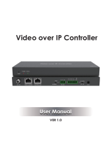
You can manage the endpoints using an Extron NAVigator System Manager (see figure 1).
The base version of the NAVigator can control up to 16 endpoints with an expansion option
that can accommodate up to 240 endpoints.
The streamed NAV signal can also be routed using a managed network switch and can be
dedicated to a specific VLAN. AV switching can be done via a control system by interfacing
to the NAV decoder or the NAVigator.
NOTE: The RS-232 and IR communications are passive pass-through only.
The encoder and decoder do not generate or respond to the RS-232 and IR
communication signals.
e
CONFIG
NAVigator
LAN
LNK
ACT
00 BNAV
NAVigator
OOB NAV/PoE
LAN
AV
Streaming
Network
Control
Network
HDMI
POWER
12V
2.0 A MAX L
Tx Rx GSG
RS-232 IRR
AUDIO
CONTROLOUTPUT
NAV 10SD 101
RESET
HDMI LOOP THRU
POWER
12V
2.0 A MAX L CONT
CTTx Rx GSG
RS-232IRR
AUDIO
CONTROLINPUT NAV 10E 101
RESET
HDMI
POWER
12V
2.0 A MAX L
Tx Rx GSG
RS-232 IRR
AUDIO
CONTROLOUTPUT
NAV 10SD 101
RESET
HDMI
POWER
12V
2.0 A MAX L
Tx Rx GSG
RS-232 IRR
AUDIO
CONTROLOUTPUT
NAV 10SD 101
RESET
HDMI LOOP THRU
POWER
12V
2.0 A MAX L CONT
CTTx Rx GSG
RS-232IRR
AUDIO
CONTROLINPUT NAV 10E 101
RESET
HDMI
POWER
12V
2.0 A MAX L
Tx Rx GSG
RS-232 IRR
AUDIO
CONTROLOUTPUT
NAV 10SD 101
RESET
Extron NAV 10E 101 Input 1
Extron NAV 10E 101 Input 2
Extron NAV 10E 101 Input 3
HDMI LOOP THRU
POWER
12V
2.0 A MAX L CONT
CTTx Rx GSG
RS-232IRR
AUDIO
CONTROLINPUT NAV 10E 101
RESET
Extron NAV 10E 201 D Input n
Extron NAV 10SD 101 #1
Extron NAV 10SD 101 #2
Extron NAV 10SD 101 #3
Extron NAV 10SD 101 #n
HDMI IN
E
HDMI IN HDMI OUT
STRM
HDMI HDCP
PWR
NAV 10G
LAN
NAV 10G
LAN
NAV 10G
LAN
NAV 10G
LAN
NAV 10G
LAN
NAV 10G
LAN
NAV 10G
LAN
TLP Pro 1025M
Blu-ray
?
Figure 1. Typical NAV Application

NAV 10E 401 D and NAV 10E 201 D Encoders • Introduction 3
About the Decoder
One or more compatible decoders, such as the NAV 10SD 501 or NAV 10SD 101, decode
the data stream back into the original video and audio signal formats and output them
locally.
System Interaction and Capabilities
Each encoder and decoder has an integrated web interface. All normal system configuration
and control is via the web interface of the NAVigator. Using a computer on the same
network and a standard web browser; such as Google Chrome™, Mozilla™ Firefox™, or
Microsoft® Edge™; you can configure any encoder or decoder unit in the system.
The embedded audio can be transported as a 2-channel LPCM uncompressed stream.
Audio can follow video to the same decoder or be broken away to a different endpoint.
A dedicated RS-232/IR port, a secure platform device (SPD), is available for distributing
RS-232 and IR data with the streamed video, such as for control of a projector.
The units are housed in 3-gang wall-mountable metal enclosures with decorator-style
faceplates available in black and white to match a variety of room decors.
The external 100 VAC to 240 VAC, 50-60 Hz power supply provides worldwide power
compatibility.
Features
• Decorator-style wallplate design — Three-gang, in-wall enclosure with a decorator-
style faceplate is available in black or white to blend with a wide range of environments.
Facilitates discreet installation near the source without a rack or external power.
• Encodes and streams video and audio over 10 Gbps fiber networks — Standard
10 Gbps fiber supports flexible system design and transmission over large distances to
any location.
• Supports HDMI 2.0 at resolutions up to 4K/60 @ 4:4:4 — HDMI up to 4K @ 60 Hz
(4096 x 2160) with full 4:4:4 chroma subsampling ensures accurate reproduction of
source images.
• PURE3 Codec — Patented by Extron, the wavelet-based compression technology
delivers high image quality with very low-latency at highly efficient bit rates. With its high
immunity to network errors and built-in error concealment, PURE3 facilitates reliable,
real-time delivery of visually lossless video over IP networks.
• PURE3 Intelligent Selective Streaming (ISS) — Leverages low motion content to
achieve extremely low bitrates while maintaining visually lossless performance.
• Interoperable with 1 Gbps NAV endpoints — Supports transmission of lower bitrate
video to 1 Gbps decoders in mixed 1 Gbps/10 Gbps solutions.
• Ultra-low latency with high quality video — Streams professional-grade video with
ultra-low latency using the unique wavelet-based Extron PURE3 codec, guaranteeing
exceptional user experience and accurate reproduction of every detail.
• AES67 audio support — Supports the AES67 audio over IP standard, providing
compatibility with Extron and third-party DSP processors.
• HDCP 2.3 compliant — Ensures display of content-protected media and
interoperability with other HDCP-compliant devices.
• (NAV 10E 401 D only) Ethernet extension — Built-in Ethernet extension facilitates
connection to peripheral Ethernet-enabled devices over the same cable as video and
audio. Saves on cabling cost in installations with any remote devices requiring LAN
connectivity.

NAV 10E 401 D and NAV 10E 201 D Encoders • Introduction 4
• SRTP stream encryption (SRTP) — Ensures encryption, message authentication,
and data integrity for video and data streams.
• Audio breakaway enables independent audio and video switching — Provides
the capability to break away an audio signal from its corresponding video signal.
• Customizable Screen Saver — Displays a user-supplied custom image, black screen,
blue screen, or the last video frame when no active video signal or stream is present.
• Priority Routing — Assign custom tags to endpoints on built-in encoder HTML pages.
Tags can be used to further classify endpoints, easily locate them on the network, or
apply rules for routing with an Extron control system.
• 802.1X port-based Network Access Control — Supports 802.1X port-based
authentication, requiring that all devices are approved before network access is granted.
• Certified FIPS 140-2 module — Extron cryptographic module meets NIST and CCS
guidelines and is certified by CMVP to the FIPS 140-2 information processing standard
in order to ensure protection of sensitive data.
• Active Directory support — Integrates with Microsoft® Active Directory, simplifying user
management, group authentication, and helping to maintain strong security policies.
• Adjustable bit rate — Selects bit rates while maintaining image quality for a more
flexible network configuration that easily adapts to different application requirements. A
non-blocking solution is available to accommodate even very large installations.
• Error concealment — Offers high immunity to network errors, ensuring reliable
transmission of high quality imagery with the ability to conceal errors even during
incidents of heavy packet loss.
• HDMI loop-through — Local HDMI output provides signal for a local display, an AV
system, or a hardware codec, enabling monitoring or sharing of content without the
need for a separate distribution amplifier.
• Embedded web interface — Intuitive, user-friendly embedded web interface simplifies
device configuration, setup, and system operation.
• EDID Minder automatically manages EDID communication between connected
devices — EDID Minder ensures that all sources power up properly and reliably output
content for display.
• Key Minder continuously verifies HDCP compliance for quick, reliable switching —
Key Minder authenticates and maintains continuous HDCP encryption between input
and output devices to ensure quick and reliable switching in professional AV environments,
while enabling simultaneous distribution of a single source signal to one or more displays.
• HDCP Visual Confirmation — When HDCP-encrypted content is transmitted to
a non-HDCP compliant display, a full-screen green signal is sent to the display for
immediate visual confirmation that protected content cannot be viewed on that display.
• Supports embedded HDMI audio signals — Directly interfaces with common digital
AV source signals for compatibility with most digital audio devices.
• Integrates with Pro Series control systems for secure, user-friendly external
control — Designed to integrate directly with Extron Pro Series control systems for
secure, encrypted RS-232 and IR control of external devices without the need for
additional control processors.
• Consumer Electronics Control (CEC) capability — CEC commands can be
triggered to control displays or other AV devices connected over HDMI.

NAV 10E 401 D and NAV 10E 201 D Encoders • Introduction 5
• Secure Platform Interface — Working natively with NAV Systems, Extron Pro Series
control systems offer flexible system management and matrix switching control via
a Secure Platform Interface that encrypts all commands from control processor to
endpoint. Together, NAV and Extron Pro Series control systems create the most secure
and reliable Pro AV over IP solution on the market.
• Multicast filtering with IGMPv3 — Supports multicast filtering with IGMPv3 for lower
bandwidth consumption. Enables use of standard network equipment.
• One-button endpoint identification — Identify endpoints with an ID button and
indicator for quick discovery of units on a network, simplifying diagnostics and installation.
• External Extron Everlast power supply included — Provides worldwide power
compatibility with high-demonstrated reliability and low power consumption.
• Extron Everlast Power Supply is covered by a 7-year parts and labor warranty
• Mounts in an included 3-gang decorator-style wallplate — The 3-gang decorator-
style wallplate is available in black or white to blend with a wide range of environments.

NAV 10E 401 D and NAV 10E 201 D Encoders • Installation 6
Installation
This section describes the installation and the operation of the NAV 10E 401 D and
NAV 10E 201 D encoders, including:
• Mounting and Rear Panel Connections
• Front Panel Features
• Connector and Cable Details
Mounting and Rear Panel Connections
The NAV 10E 401 D and NAV 10E 201 D encoders can be installed in the provided three-
gang mud ring or a compatible junction box.
A decorator-style wallplate cover is supplied.
The installation must conform to national and local electrical codes and to the size
requirements of the wall plate.
ATTENTION:
• Installation and service must be performed by authorized personnel only.
• L’installation et l’entretien doivent être effectués par le personnel expérimenté et
autorisé uniquement.
• Extron recommends installing the encoder into a grounded, UL Listed electrical
junction box.
• Extron recommande d’installer le encoder dans une boîte de dérivation électrique
mis à la terre, certifiée UL.
• If the encoder will be installed into fine furniture, it is best to hire a licenced, bonded
craftsperson to cut the access hole and perform the physical installation so the
surface will not be damaged.
• S’il est prévu d’installer le encoder dans du beau mobilier, il est préférable de
faire appel à un artisan autorisé et qualifié pour couper le trou d’accès et réaliser
l’installation de telle façon que la surface ne soit pas endommagée.
• Follow all national and local building and electrical codes that apply to the
installation site.
• Respectez tous les codes électriques et du bâtiment, nationaux et locaux, qui
s’appliquent au site de l’installation.
• For the installation to meet UL requirements and to comply with National Electrical
Code (NEC), the encoder must be installed in a ULListed junction box. The end
user or installer must furnish the junction box. It is not included with the unit.
• Pour que l’installation respecte les exigences UL et soit conforme au National
Electrical Code (NEC) américain, le encoder doit être installé dans une boîte de
dérivation certifiée UL. Il incombe à l’utilisateur final ou à l’installateur de fournir la
boîte de dérivation. Cet équipement n’est pas inclus avec l’unité.

NAV 10E 401 D and NAV 10E 201 D Encoders • Installation 7
UL and Safety Guidelines
The following UL guidelines pertain to the installation of the decorator-style wallplate
decoders into a wall or furniture.
• These units are not to be connected to a centralized DC power source or used beyond
their rated voltage range.
• These units must be installed in UL-listed junction boxes.
• These units must be installed with conduit in accordance with National Electrical Code.
Choosing and Preparing the Site
Choose the site
Choose a location that allows cable runs without interference. Allow enough depth for
both the wall box and the cables. The box should be at least 3.0 inches (7.6 cm) deep
to accommodate the connectors and cables. Install the cables into the wall, furniture, or
conduits before installing the encoder.
The encoder fits into a standard US three-gang junction box or mud ring and includes a
decorator-style wallplate and a metal mud ring. Optional ULListed junction boxes, external
junction boxes, and surface mounting boxes are available for use with the unit. Please
see the product specifications, available on the Extron website, www.extron.com for the
product dimensions.
NOTE: The encoder is wider than a standard 3-gang device. You cannot install
another wall-mounted device immediately adjacent to this device.
Americans with Disabilities Act (ADA) compliance
When planning where to install the encoder, you may need to consider factors affecting
accessibility of the encoder such as height from the floor, distance from obstructions,
and how far a user must reach to access the connectors. For guidelines, see sections
307 (“Protruding Objects”) and 308 (“Reach Ranges”) of the 2010 ADA Standards for
Accessible Design available at:
http://www.ada.gov/regs2010/2010ADAStandards/2010ADAStandards.pdf.

NAV 10E 401 D and NAV 10E 201 D Encoders • Installation 8
Prepare the Site
To prepare the site:
1. Using either of the following sizing methods:
• Print the applicable mounting template, available on the Extron website and tape
your template to the mounting surface.
• Place the wall box against the installation surface, and mark the opening guidelines.
2. Cut out the material from the marked area. Protect the surface prior to and while cutting
so the surface is not damaged.
3. Test the fit by inserting the encoder or wall box (if applicable) into the opening. The rear
connectors on the encoder should fit easily into the opening.
4. Enlarge or smooth the edges of the opening if needed.
5. If using a mounting bracket, install the junction box or mud ring into the wall or
furniture (see figure 2).
Detail A
0.75" #6-32 Scre
w
Backing Clip
Backing Clip
Sheet Rock
Sheet Rock
Mounting Bracket
Mounting Bracket
Detail B
1.25" #6-32 Scre
w
Backing Clip can
be in either orientation.
See Detail A or Detail B.
Figure 2. Installing a Mounting Bracket
a. Place 0.75 (1.90 cm) to 1.25 inch (3.18 cm) long #6-32 machine screws through
the large holes in the four corners of the mouting bracket.
b. Loosely fasten the mounting bracket clip to the on the end of each screw.
c. Insert the mounting bracket into the opening in the wall (see step 2).
d. Rotate each mounting bracket clip so that the tab is behind the installation surface
to hold the bracket suggly against the surface when the screw is tightened.
NOTE: The mounting bracket clip can be installed as shown in Detail A or
Detail B of figure 2.
e. Use a screwdriver to fasten the screws and bracket clips in place.
6. If using a junction box, secure it with nails or screws, leaving the front edge flush with
the outer wall or furniture surface (see figure 3 on page 9).
NOTE: Read any installation instructions and UL guidelines that come with the
mounting devices, then install the box or mud ring in the opening at the installation
site.

NAV 10E 401 D and NAV 10E 201 D Encoders • Installation 9
Flush with
W
all Surface
Wall Stud
Metal Junction Box
Figure 3. Installing a Junction Box
7. Run cables to the mounting location, leaving enough slack for device installation.
8. Feed the cables through the opening and through the wall box punch-out holes (if
applicable), securing them with cable clamps to provide strain relief and so they do not
slip back down into the wall or furniture.
NOTE: Connect the network cable and (if applicable) the external power supply, but
do not apply power yet.
9. Trim back and insulate exposed cable shields with heat shrink to reduce the chance of
short circuits. The outer foil shield can be cut back to the point where the cable exits the
cable clamp.

NAV 10E 401 D and NAV 10E 201 D Encoders • Installation 10
Make Rear Panel Connections
Connect the cables to the rear of the unit (see figure 4 for connector details).
POWER
12V
2.0A MAX
+
CONTROL
NAV 10G
Tx Rx S G
G
RS-232 IR
CCCBBB
AAA
NOTE: *NAV 10E 201 D amperage is 1.7A max.
NAV 10E 401 D amperage is 2.0 A max.
*
Figure 4. NAV 10E 401 D and NAV 10E 201 D Rear Panel Connectors
A NAV 10G port — Connect to an Ethernet LAN on which one or more decoders also
reside for streaming and control.
WARNING: This unit outputs continuous invisible light (Class 1 rated), which
may be harmful to the eyes; use with caution. Plug the attached dust cap into the
optical transceiver when the fiber optic cable is unplugged.
AVERTISSEMENT : Le grilles de commutation de la gamme FOX cartes d’entrée/
sortie fibre optique émet une lumière invisible en continu (équipement de classe
1) qui peut être dangereux pour les yeux, à utiliser avec précaution Branchez la
protection contre la poussière dans l’ensemble émetteur/récepteur lorsque le
câble fibre optique est débranché.
NOTE: Ensure that you use the proper fiber cable for your unit. Typically,
singlemode fiber has a yellow jacket and multimode cable has an orange or aqua
jacket.
B Control RS-232/IR port — Connect a serial RS-232 signal, a modulated IR signal,
or both to this 3.5 mm, 5-pole direct insertion connector for bidirectional RS-232 and
IR communication with connected remote controlled devices using an Extron control
system (see Control connector on page 15 to wire the connector).
C Power connector — Connect the included external 12 VDC power supply to this
2-pole direct insertion connector to power the encoder (see Power supply wiring on
page 16 to wire the connector).
Test and Troubleshoot
1. Power up the system. Check that after approximately 45 seconds, the front panel LEDs
indicate normally (Power LED and Stream LEDs lit steadily green).
2. Make adjustments to wiring or configuration as needed. Remember that the rear panel
ports are not accessible after the encoder is mounted.

NAV 10E 401 D and NAV 10E 201 D Encoders • Installation 11
Complete the Physical Installation
Mount the encoder to a wall or furniture as follows:
NOTE: Extron recommends taking safety precautions to avoid electrostatic discharge
issues during installation.
1. Insert the cabled encoder into the mud ring or junction box within the wall or furniture,
aligning the mounting holes in the encoder mounting tabs with those in box or mud
ring.
2. Secure the encoder to the junction box, wall or surface mounting box, or mud ring as
follows (see figure 5):
NAV 10E 201 D
HDMI IN HDMI OUT
E
STRM
HDMI HDCP
PWR
Mounting
Screws
(6 Plcs)
NOTE: Ensure that the vent holes on the
top and bottom of the encoder remain
unobstructed.
Figure 5. Installing the Encoder in a Junction Box
a. Insert the included screws through the mounting holes at diagonal corners of the
unit and into the corresponding threaded holes in the box or mud ring.
b. Using a Phillips screwdriver, tighten the screws until snug.
ATTENTION: Do not overtighten the screws.
ATTENTION : Veillez à ne pas trop serrer les vis.
c. Attach the faceplate to the encoder: insert the six included screws through the
circular holes in the faceplate and the tabs on the encoder. Tighten the screws
using a flat bladed screwdriver until snug.

NAV 10E 401 D and NAV 10E 201 D Encoders • Installation 12
Front Panel Features
figure 6
HDMI IN HDMI OUT
E
STRM
HDMI HDCP
PWR
RESET
NAV 10G
ID
LNK
ACT
CONFIG
NAV - EXT
BBBDDDCCCAAA
FFF
EEE
NAV 10E 401
D
only
Figure 6. NAV 10E 401 D and NAV 10E 201 D Front Panel Features
NOTES:
• Figure 6 shows a NAV 10E 401 D. The NAV 10E 201 D is similar; the only
exception is lack of an Extension port (D).
• Items C and F are visible only when the faceplate is removed.
Connectors
A HDMI IN port — Receives the HDMI video input (or DVI, with an appropriate adapter)
from the HDMI output port of the digital video source.
B HDMI OUT port — Outputs looped-through HDMI video for local monitoring of the
source signal.
NOTE: See LockIt Lacing Brackets on page 14 to securely fasten the HDMI
connectors (A and B) to the encoder.
C Configuration (CONFIG) port — Connect a PC into the encoder for configuration
of the encoder. The port uses IP over USB technology; the IP address is always
203.0.113.22 and CANNOT be changed. The Config port is also discoverable via
Toolbelt and Product Configuration Software (PCS).
D NAV - Ext(ension) port (NAV 10E 401 D only) — If desired, connect another
networked device to this port. The port acts as a networked switch to the NAV 10G
port (see A on page 10).
NOTES:
• See Ext connector on page 15 to properly wire the Extension connector.
• The EXT (RJ-45) port LED indicates as follows:
• Act (amber) LED — Indicates transmission of data packets on the RJ-45
connector. This LED blinks as the encoder communicates.
• Link (green) LED — Indicates that the encoder is properly connected to
an Ethernet LAN. This LED lights steadily.
1/88