NAPCO LIBRA LIB-P432EX Installation Instructions Manual
- Category
- Wall transmitters
- Type
- Installation Instructions Manual
This manual is also suitable for
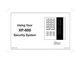
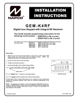
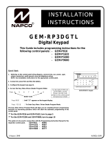
NAPCO LIBRA DXK4RF-433 is a digital keypad with an integral RF receiver compatible with LIBRA LIB-P432EX, LIB-P432EXT, LIB-P432EXT-230 control panels. It can be used to fully program the control panel. With its easy-to-read LCD display, the keypad provides intuitive operation. The built-in receiver allows for wireless connectivity with compatible NAPCO transmitters, such as smoke detectors, motion sensors, and door/window sensors. This enables the creation of a comprehensive security system that can be monitored and controlled remotely.
NAPCO LIBRA DXK4RF-433 is a digital keypad with an integral RF receiver compatible with LIBRA LIB-P432EX, LIB-P432EXT, LIB-P432EXT-230 control panels. It can be used to fully program the control panel. With its easy-to-read LCD display, the keypad provides intuitive operation. The built-in receiver allows for wireless connectivity with compatible NAPCO transmitters, such as smoke detectors, motion sensors, and door/window sensors. This enables the creation of a comprehensive security system that can be monitored and controlled remotely.


-
 1
1
-
 2
2
-
 3
3
-
 4
4
-
 5
5
-
 6
6
-
 7
7
-
 8
8
-
 9
9
-
 10
10
-
 11
11
-
 12
12
-
 13
13
-
 14
14
-
 15
15
-
 16
16
-
 17
17
-
 18
18
-
 19
19
-
 20
20


NAPCO LIBRA LIB-P432EX Installation Instructions Manual
- Category
- Wall transmitters
- Type
- Installation Instructions Manual
- This manual is also suitable for
NAPCO LIBRA DXK4RF-433 is a digital keypad with an integral RF receiver compatible with LIBRA LIB-P432EX, LIB-P432EXT, LIB-P432EXT-230 control panels. It can be used to fully program the control panel. With its easy-to-read LCD display, the keypad provides intuitive operation. The built-in receiver allows for wireless connectivity with compatible NAPCO transmitters, such as smoke detectors, motion sensors, and door/window sensors. This enables the creation of a comprehensive security system that can be monitored and controlled remotely.
Ask a question and I''ll find the answer in the document
Finding information in a document is now easier with AI
Related papers
-
 NAPCO EXPRESS XP-600 User manual
-
 NAPCO GEM-RP8 User manual
-
 NAPCO EXPRESS XP-600 User manual
-
 NAPCO Gemini GEM-P1632 Installation Instructions Manual
-
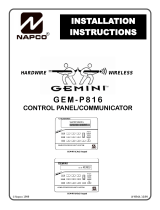
 Napco Security Technologies GEM-P816 User manual
-
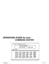 NAPCO SECURITY COMMAND CENTER Operating instructions
-
NAPCO ISECHUB User manual
-
 NAPCO XP-400 Using Instruction
-
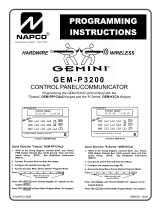 NAPCO GEM-P3200 User manual
-
 NAPCO Gemini GEM-RP1CAe2 Installation Instructions Manual


Other documents
-
 Napco Security Technologies WI1501A User manual
-
 Napco Security Technologies Gemini GEM-P1664 User manual
-
Gemini Gemini GEM-P3200 Programming Instructions Manual
-
Visonic CL-80 Installation guide
-
Dahua ARA24-W2 User manual
-
Satel RK-1K User manual
-
ADEMCO VISTA-48D Installation And Setup Manual
-
ADEMCO VISTA 10 User manual
-
-
Honeywell ADEMCO VISTA-20PSIA User manual

