Page is loading ...

Installation Instructions D Series
Issue Date July 14, 2016
© 2016 BASO Gas Products 1
Part No. BASO-INS-DSERIES Rev. - www.baso.com
Spark Igniter Applications
with Flame Rectification Sensing
Application
This document is intended to aid the appliance
engineer or authorized service contractor in an
Intermittent Pilot Ignition (IPI) or Direct Spark Ignition
(DSI) application. Spark igniters are manufactured with
a variety of tips and mounting configurations.
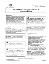
DC2/DC3 Spark/Sensor Assembly (DSI)
Figure 1: Mounting Position Example
Good Practice Rules
The following are good practice rules for governing the
location of the igniter assembly:
• Locate the igniter assembly in a position that has a
fixed relation to the main burner.
• Locate the igniter assembly in such a position that it
does not receive the full force of igniting puffs from
the main burner.
• Locate the igniter assembly in a position that will
allow ready removal for cleaning.
After Installation
When the igniter assembly has been installed, carefully
make the following observations and tests:
1. Ensure the pilot gas readily ignites and that the
flame is sensed, i.e., main valve is energized (pilot
application). Ensure main burner gas readily ignites
and is sensed, i.e., main valve is energized prior to
lockout (DSI application).
2. Ensure the main burner flames do not impinge on
any part of the igniter assembly, except the
electrodes.
3. Ensure the igniter assembly will ignite the main
burner under various pressure and voltage
conditions if the main valve is energized.
4. Ensure the burner remains lit and the igniter
assembly does not cycle the valve:
• when the main burner is ignited from a cold
start
• when the main burner is ignited with the
appliance at the maximum temperature
conditions of operation
• with normal variation in air adjustments of the
main burner
• with rapid Off and On operation of the main
burner with the combustion chamber cold
• with rapid Off and On operation of the main
burner with the combustion chamber hot
• with continued operation of the main burner
5. To ensure proper operation, the igniter assembly
must produce a satisfactory microamperage.
Note: When an igniter is to be applied to an appliance
already in the field, obtain the appliance
manufacturers' recommendations for the correct
pilot specification and location dimensions for the
particular model appliance.
Flame Sensor Output Test
When the DSI assembly is applied properly, the flame
sensor will produce a microamperage. Minimum
operating microamperage must be obtained to give
trouble free performance. Check with your ignition
manufacturer for proper microamp reading.
1007 South 12
th
Street
PO Box 170
Watertown, WI 53094
1-877-227-6427 (1-877-BASOGAS)
/