
®U.S. Registered Trademark
Copyright © 1999 Honeywell Inc. • All Rights Reserved
INSTALLATION INSTRUCTIONS
69-1174
S8701/S8702 Direct Spark
Ignition Controls
APPLICATION
S8701 and S8702 Direct Spark Ignition Controls are
designed for use in commercial cooking and other gas
heating applications which require direct ignition and flame
safety control of gas burners. S8701/S8702 controls are
used to ignite the main burner(s), sense the flame and
control the gas valve in these applications, see Table 1.
Model Flame Sense Trials for Ignition Spark/Sense Prepurge
S8701D remote 1 1 No
S8702D remote 1 2 No
S8702F remote 3
a
2No
S8702K remote 1 2 Yes
S8702M remote 3
a
2 Yes
The S8701 is a single spark, single flame sense, direct
ignition control that is compatible with dual rod systems.
The S8702 is a dual spark, dual flame sense, direct
ignition control capable of igniting and sensing flame on
two separate gas burners that are fed by a single gas
valve. The S8702 is compatible with dual rod systems
only.
Table 1. S8701/S8702 Models.
a
S8702 F and M models include an auto-reset from lockout after 1 hour.
Planning the Installation
WARNING
Fire or Explosion Hazard.
Can cause property damage, severe injury,
or death.
Follow these warnings exactly:
1. Plan the installation as outlined below.
2. Plan for frequent maintenance as described in
the Maintenance section.
Review the following conditions that can apply to your
specific installation and take the precautionary steps
suggested.
Frequent Cycling
This control is designed for use on commercial cooking
appliances that typically cycle 400 times a day, year round.
Perform a monthly checkout.
Water or Steam Cleaning
If a control gets wet, replace it. If the appliance is likely to
be cleaned with water or steam, protect (cover) the control
and wiring from water or steam flow. Mount the control
high enough above the floor so it does not get wet during
normal cleaning procedures.
High Humidity or Dripping Water
Dripping water can cause the control to fail. Never install
an appliance where water can drip on the control. In
addition, high ambient humidity can cause the control to
corrode and fail. If the appliance is in a humid atmosphere,
make sure air circulation around the control is adequate to
prevent condensation. Also, regularly check out the
system.
IMPORTANT
Always install a splash cover to protect the
control from water damage.
Corrosive Chemicals
Corrosive chemicals can attack the control, eventually
causing a failure. If chemicals are used for routine
cleaning, avoid contact with the control. Where chemicals
are suspended in air, as in some industrial or agricultural
applications, protect the control with an enclosure.
Dust or Grease Accumulation
Heavy accumulations of dust or grease can cause the
control to malfunction. Where dust or grease can be a
problem, provide covers for the control to limit contamina-
tion.

69-1174
2
S8701/S8702 DIRECT SPARK IGNITION CONTROLS
a
Valve used must be designed for DSI application.
b
Separate spark igniter and flame sensor mounted on a
common bracket.
INSTALLATION
When Installing this Product…
1. Read these instructions carefully. Failure to follow
them could damage the product or cause a hazard-
ous condition.
2. Check the ratings given in the instructions and on
the product to make sure it is suitable for your
application.
3. The installer must be a trained, experienced service
technician.
4. After installation is complete, check out system
operation.
WARNING
Fire or Explosion Hazard.
Can cause property damage, severe injury
or death.
If a new gas control is to be installed, turn off gas
supply before starting installation.
Be sure to conduct a gas leak test after the control
is installed.
CAUTION
Electric Shock Hazard.
Can cause personal injury or equipment
damage.
Disconnect power supply before wiring.
Model
No.
Spark
Igniter
Flame
Sensor
Valve Required
a
S8701/
Q347A Q354A
Honeywell VR8205
S8702
Q366
b
gas valves or
equivalent
Heat
Excessively high temperatures can damage the control.
Make sure the maximum ambient temperature at the
control does not exceed the rating of the control, see Table
2. If the appliance operates at very high temperatures, use
insulation, shielding, and air circulation, as necessary, to
protect the control. Proper insulation or shielding should be
provided by the appliance manufacturer; verify proper air
circulation is maintained when the appliance is installed.
Table 2. S8701/S8702 Ambient Temperature Ratings.
IMPORTANT
If this is a replacement application, follow the
appliance manufacturer’s instructions, if avail-
able. The manufacturer usually provides wiring
diagrams, start-up and checkout instructions and
the service procedures for their system. If the
manufacturer’s instructions are not available, this
information may be used as a general guide.
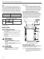
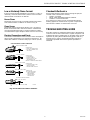
Mounting The S8701/S8702 Control
Select a location within 6 ft (1.8m) of the burner that will
permit a direct cable route to the spark igniter terminal.
Ready access to the terminals is necessary for wiring and
servicing. The S8701/S8702 control may be mounted in
any position. Use No. 6-32 machine screws or No. 8
sheetmetal screws 1 inch long for fastening. Fasten
securely. Do not exceed the ambient temperature rating
given in Table 2.
M16233
13/16 (21)
1-1/8
(29)
2
(50)
2-13/16 (72)
3-15/16 (100)
3-3/8 (86)
3-3/8
(86)
5/17 (7)
7/8 (23)
5-3/16
(130)
3/16 (4)
Operation Ambient Temperature
50 Hz -40°F to 160°F
60 Hz -40°F to 175°F
Table 3. System Requirements.
Fig. 1. S8701/S8702 Dimensions.
Mounting Auxiliary Controls
Mount the spark igniter, flame sensor, temperature control,
transformer, gas control and any other auxiliary controls
according to the manufacturer’s instructions.
NOTE: The S8701 and S8702 installations require a 24V
transformer rated to handle both the S8701/
S8702 current and the gas valve current. Table 4
shows the transformer rating necessary for
various loads.

69-1174
3
S8701/S8702 DIRECT SPARK IGNITION CONTROLS
RMS
Temperature
Rating
Cable Type
Voltage Rating
°F °C
UL Style 3257 10,000 482 250
Table 4. Transformer Ratings for S8701/S8702 and
Dual Valve Combination Gas Controls.
Wiring the S8701/S8702 Control
1. Connect system components to the S8701/S8702
terminals as shown in the wiring diagrams, Figs. 2
and 3. Refer to the appliance manufacturer’s
instructions for wiring any other auxiliary controls.
2. Adjust temperature control heat anticipator to match
system current draw. The current draw equals the
total current required for the S8701 or S8702
(0.15A) plus the gas valve and all other 24 V control
loads (vent dampers, prepurge relays, etc.). Gas
valve must be designed for the DSI application.
NOTE: Use only recommended ignition cable (see
Table 5) to connect the S8701/S8702 with the
spark igniter. Cable must not run in continuous
contact with a metal surface or spark voltage
will be greatly reduced; use ceramic standoff
brackets if necessary. Cable length must not
exceed 6 ft (1.8m).
Q347
SPARK
IGNITER
Q354 FLAME
SENSOR
BURNER
IGNITER AND
BURNER GROUND
L1
(HOT)
L2
1
2
3
1
2
3
POWER SUPPLY. PROVIDE DISCONNECT MEANS AND OVERLOAD
PROTECTION AS REQUIRED.
ALTERNATE LIMIT CONTROLLER LOCATION.
MAXIMUM IGNITER-SENSOR CABLE LENGTH: 6 FT. (1.8 M) OR LESS.
S8701D CONTROL MODULE
ANY COMBINATION
GAS CONTROL
2.0A MAX.
TEMPERATURE
CONTOLLER
LIMIT CONTROLLER
TRANSFORMER
M16232A
FLAME
SENSE
ALARM
VALVE
GND
VALVE (GND)
24 Vac (GND)
24 Vac
BURNER
(GND)
SPARK
ALARM, IF USED
Fig. 2. S8701 Wiring Diagram.
Minimum VA
Rating (24V
transformer)
Total Valve
Current
(in amperes)
S8701/S8702
(in amperes)
20 up to 0.6 0.15
30 0.6 to 1.0 0.15
40 1.0 to 1.4 0.15
55 1.4 to 2.0 0.15
Wiring
General Precautions
1. Check the wiring diagram furnished by the
heating appliance manufacturer, if available, for
circuits different from the ones shown. Carefully
follow any special instructions affecting the general
procedures outlined below.
2. All wiring must comply with applicable electrical
codes and ordinances.
3. Disconnect the power supply before wiring to
prevent electrical shock or equipment damage.
4. If installing a separate Q345A flame sensor, the
sensor leadwire should be kept as short as possible
and should not be allowed to rest against grounded
metal surfaces.
5. A common ground is required for the S8701/S8702,
the spark igniter and the main burner. The 24V
(GND) terminal does not internally ground the
transformer. The 24 V (GND) terminal must be
grounded to the equipment chassis separately. Any
auxiliary controls or limits must not be in the
grounded leg.
6. Ignition cable should not touch any metal surface or
current carrying wires. It must not be more than 6 ft
(1.8m) long.
7. Do not short valve terminals as this may damage the
temperature controller, the transformer or the
S8701/S8702.
Table 5. Recommended Ignition Cable.

69-1174
4
S8701/S8702 DIRECT SPARK IGNITION CONTROLS
Fig. 3. S8702 Wiring Diagram.
Grounding the S8701/S8702 Spark Igniter and
Main Burner
For the system to operate properly, spark igniter, flame
sensor bracket, the burner (GND) terminal on the 24V
(GND) terminal, and the S8701/S8702 control must share
a common ground with the main burner. Use thermoplastic
insulated wire with a minimum rating of 105°C (221°F) for
the ground wire; asbestos insulation is not acceptable. If
necessary, use a shield to protect the wire from radiant
heat generated by the burner.
IMPORTANT
Use moisture resistant 18 AWG wire rated for
continuous duty up to 105
°
C (221
°
F). Connec-
tions must be clean and tight.
Connect the ground wire as follows:
1. Fit one end of the ground wire with a female 1/4 in.
quick-connect terminal and connect it to the male
quick connect GND (Burner) terminal on the S8701/
S8702 control.
2. Strip the other end of the GND (Burner) wire and
fasten it under the igniter bracket mounting screw. If
necessary, use a shield to protect the wire from
radiant heat. The burner serves as the common
grounding area.
3. Fit one end of another ground wire with a female 1/4
in. quick connect terminal and connect it to the male
quick connect 24V (GND) terminal on the S8701/
S8702 control.
4. Strip the other end of the 24V (GND) wire and fasten
it to the burner ground.
5. If used with a separate flame sensor, make sure the
bracket is connected to the burner ground.
NOTE: It is not necessary that the burner is earth
grounded.
STARTUP AND CHECKOUT
The following start-up and checkout procedures are basic
to all S8701 and S8702 control modules. If this is a
replacement application, refer to the specific instructions
provided by the heating appliance manufacturer (if
available). Also, since the auxiliary controls used on any
DSI system may differ, refer to the manufacturer’s
instructions for start-up and checkout procedures for other
system components.
NOTE: If one of the system components fail, the S8701/
S8702 will either not operate or it will go into
safety lockout (depending on the type of failure).
If the system does not perform as outlined in
Start System and Check Trial for Ignition steps
below, refer to the SERVICE section to deter-
mine the cause.
Gas Leak Test
If the gas control has been replaced as a part of the S8701
or S8702 installation, perform the following test for gas
leaks.
WARNING
Fire or Explosion Hazard.
Can cause property damage, severe injury
or death.
To avoid possible explosion or fire, perform Gas
Leak Test.
With the main burner in operation, paint the pipe joints and
valve gasket with a rich soap and water solution. Bubbles
indicate a gas leak. To stop leak, tighten joints and screws or
replace the gasket. Never use a flame to check for gas leaks.
START SYSTEM
1. Turn on the power and the gas supply.
Set the temperature control to request heat and
watch for a spark at the igniter (S8701D, S8702D
models have no delay on start-up. S8702K and M
models have a predetermined delay on start-up for
prepurge.). Time the length of the spark operation; it
must be within the Trial for Ignition (TFI) timing
period (see Table 6).
2. Check that the system starts as follows: Spark turns
on, gas valve opens at once, and burner ignites after
gas reaches main burner. Once burner flame is
established, spark igniter cuts off. For S8702
models; flame must be established on both burners
for spark igniters to turn off.
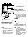
Q347
SPARK
IGNITER
Q354 FLAME
SENSOR
BURNER
IGNITER AND
BURNER GROUND
L1
(HOT)
L2
1
2
3
1
2
3
POWER SUPPLY. PROVIDE DISCONNECT MEANS AND OVERLOAD
PROTECTION AS REQUIRED.
ALTERNATE LIMIT CONTROLLER LOCATION.
MAXIMUM IGNITER-SENSOR CABLE LENGTH: 6 FT. (1.8 M) OR LESS.
S8702D CONTROL MODULE
ANY COMBINATION
GAS CONTROL
2.0A MAX.
TEMPERATURE
CONTOLLER
LIMIT CONTROLLER
TRANSFORMER
M16267A
SENSE 1
SENSE 2
ALARM
VALVE
GND
VALVE (GND)
24 Vac (GND)
24 Vac
BURNER
(GND)
SPARK 1
SPARK 2
Q347 SPARK
IGNITER
Q354 FLAME
SENSOR
BURNER
IGNITER AND
BURNER GROUND
3
ALARM, IF USED

69-1174
5
S8701/S8702 DIRECT SPARK IGNITION CONTROLS
NOTE: If the gas control has been replaced or serviced,
lightoff may not be satisfactory until air has been
purged from the gas line or the gas input and
combustion air have been adjusted (see
manufacturer’s instructions).
Table 6. Trial for Ignition Periods for the S8701/S8702.
Check Trial for Ignition
1. Check device label on control to determine correct
Trial for Ignition time.
2. With the system power off and the thermostat or
temperature control set to call for heat, manually
shut off the gas supply.
3. Turn power on to energize the S8701/S8702,
immediately start timing when the gas valve turns
on.
4. Determine the number of seconds to drop-out of the
gas valve. It should not exceed the trial for ignition
time shown in Table 6.
5. After spark cutoff, manually reopen gas supply cock.
No gas should flow to the main burner.
6. Reset system as described below.
Resetting S8701 and S8702 After Safety
Lockout
If the control goes into safety lockout, it will remain locked
out for D and K models, until the system is reset.
To reset the system:
Adjust the temperature control setting to below room
temperature, wait 5 seconds, and move the temperature
control setting up to request heat or remove 24V power
and reapply. Normal ignition should occur as described in
Start System section.
NOTE: F and M models have the 3 retry feature for Trial
for Ignition with 30 second interpurge between
TFI periods. Safety lockout on the F and M
models occurs after the 3rd TFI period if flame is
not sensed. F and M models also automatically
reset after one (1) hour in lockout.
CHECKOUT
Start the system and observe operation through at least
one complete cycle to make certain all controls are
operating safely.
Sequence of Operation
The S8701/S8702 controls perform the following basic
functions:
• Supplies power to the electronic pulse-generator
circuit for the spark igniter (14,000 volts, open circuit).
• Allows up to 23.75 seconds (maximum) for ignition
and 1 or 3 trials before system safety lockout occurs
(see Table 4).
• Senses burner flame for safe lighting (2 burners for
S8702).
• Shuts off spark after burner is lit.
The S8701 and S8702 are powered by a 24 Vac trans-
former and activated when the temperature control
requests heat.
Operation is as follows:
When the S8701/S8702 control is activated by the
temperature control’s request for heat, S8701/S8702
controls perform a safe-start check that determines proper
operation of the control before beginning the normal
sequence of operation. Once the Safe Start Check
operation passes, the control turns on the spark circuit and
at the same time, the S8701/S8702 opens the gas
control’s main valves, which allows gas to flow to the main
burner.
Power is supplied to the generator until:
• The main burner(s) lights and the flame sensor
current reaches 1.0 µA, or
• The ignition activation period ends
If the main burner lights, a flame sensing circuit is com-
pleted through the flame to the burner head to ground.
This current flow sets the Trial for Ignition timer to the reset
(normal) condition and interrupts the spark ignition circuit
(flame sense must occur on both burners on a S8702).
Should the current flow be interrupted, i.e., flame out
condition, the trial for ignition period begins again.
The S8701/S8702 will keep the gas control main valve
open as long as there is a request for heat and flame
current through the flame sensing circuit. If, however, the
trial for ignition timing period ends before the main burner
lights or the flame sensor establishes enough current, the
system will go into safety lockout or interpurge if the
control is an F or M model.
When the system goes into safety lockout, power to the
spark generator is interrupted, the power to the gas valve
is interrupted and the alarm circuit is completed and the
LED is steady on. The system will stay locked out until it is
reset by moving the temperature control setpoint to below
room temperature, no request for heat, for 5 seconds.
Then, re-energize the system by moving the temperature
control setpoint 5°F (3°C) above room temperature. Or,
remove 24 Vac power to the control then reapply.
NOTE: F and M models will automatically reset from
lockout after one (1) hour.
Model
Specified Trial for
Ignition (TFI) (stamped
on control)
Trial for
Ignition Should
Not Exceed
S8701;
S8702
4.6 sec
6.6 sec
11.6 sec
21.6 sec
5.05 sec
7.25 sec
12.75 sec
23.75 sec

69-1174
6
S8701/S8702 DIRECT SPARK IGNITION CONTROLS
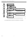
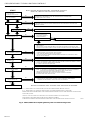
Fig. 4. S8701/S8702 Sequence of Operation for 1 Trial Models (B, D, J, and K Models).
START
PREPURGE
(J AND K MODELS ONLY)
SAFE START CHECK
TRIAL FOR IGNITION
MAIN BURNER
OPERATION
END
THERMOSTAT CALLS FOR HEAT
SAFE START CHECK. LED BLINKS RAPIDLY.
PREPURGE - J & K MODELS ONLY
SPARK GENERATOR POWERED
MAIN VALVE OPERATORS OPEN.
IF NO SPARK, B, D, J, AND K MODELS GO INTO LOCKOUT
AFTER ONE (1) TRIAL FOR IGNITION PERIOD.
ALARM CIRCUIT IS ACTIVATED.
LED IS ON STEADY. SYSTEM MUST BE RESET.
IF FLAME CURRENT SENSED:
(MUST BE SENSED AT BOTH
BURNERS ON S8702)
SPARK GENERATOR IS SHUT OFF.
LOCKOUT TIMER IS RESET.
IF FLAME CURRENT IS NOT SENSED:
B, D, J, AND K MODELS GO INTO LOCKOUT
AFTER ONE (1)TRIAL FOR IGNITION PERIOD.
LED IN ON. SYSTEM MUST BE RESET.
MAIN BURNER OPERATION
UNIT MONITORS BURNER
FLAME CURRENT.
LOSS OF FLAME
SPARK GENERATOR IS POWERED.
B, D, J, AND K MODELS GO INTO LOCKOUT AFTER
ONE (1) TRIAL FOR IGNITION PERIOD. LED IS ON STEADY.
SYSTEM MUST BE RESET.
TEMPERATURE CONTROLLER
IS SATISFIED.
POWER TO UNIT IS INTERRUPTED.
VALVES CLOSE.
MAIN BURNER(S) ARE OFF.
DURING NORMAL OPERATION LED BLINKS ONCE PER SECOND.
M18058
NOTES: B, D, J, AND K MODELS GO THROUGH ONE (1) TRIAL FOR IGNITION PERIOD BEFORE LOCKOUT.
LOCKOUT = VALVE CLOSED PLUS SPARK OFF PLUS ALARM ACTIVATED PLUS LED ON STEADY.

69-1174
7
S8701/S8702 DIRECT SPARK IGNITION CONTROLS
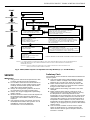
Fig. 5. S8701/S8702 Sequence of Operation for Retry Models (E, F, L and M Models).
SERVICE
IMPORTANT
1. Only persons trained and experienced in DSI
systems should service this equipment.
2. If a condition exists that causes the S8701 or
S8702 control to go into safety lockout, meter
readings must be taken quickly after restart—
within the Trial-for-Ignition period.
3. Always de-energize the system for at least 5
seconds before recycling for further tests.
4. Always turn off gas supply before performing
ignition checks.
5. S8701 and S8702 control cannot be repaired. If
the troubleshooting procedure indicates a
malfunction in the S8701 or S8702, it must be
replaced.
6. The following service procedures are for the
S8701/S8702 and basic DSI systems. On all
installations, refer to the appliance
manufacturer’s service instructions.
Preliminary Check
The following checks should be made before troubleshoot-
ing the system.
1. Check for power to the heating appliance and the
S8701 or S8702. Voltage to the control should be
between 20.5 and 28.5 Vac when in run mode.
2. Make certain that the manual shut-off valve in the
supply line and the gas cock knob on the combina-
tion gas control valve are open.
3. Make certain that all wiring connections are clean
and tight.
4. Make certain that the S8701 or S8702 is not in
safety lockout. De-energize the system by moving
the temperature control setpoint below room
temperature or by removing the 24 Vac power to the
S8701/S8702 control. Wait at least 5 seconds and
reenergize the system by moving the thermostat or
temperature control setpoint 5°F (3°C) above room
temperature. Return setpoint to normal temperature
setting or by re-applying 24 Vac power to the S8701/
S8702 control.
5. Check ceramic insulator on flame sensor, spark
igniter or igniter/sensor. A cracked insulator will
allow current to leak to ground. Replace device if
insulator is cracked.
START
PREPURGE
(L AND M MODELS ONLY)
SAFE START CHECK
TRIAL FOR IGNITION
MAIN BURNER
OPERATION
END
THERMOSTAT CALLS FOR HEAT
SAFE START CHECK. LED BLINKS RAPIDLY.
PREPURGE - L & M MODELS ONLY
INTERPURGE
SPARK GENERATOR POWERED
MAIN VALVE OPERATORS OPEN.
IF NO SPARK, E, F, L, AND M MODELS GO INTO LOCKOUT
AFTER THREE (3) TRIAL FOR IGNITION PERIODS.
ALARM CIRCUIT IS ACTIVATED. LED
IS ON STEADY. SYSTEM WILL AUTOMATICALLY
RETRY AFTER ONE (1) HOUR.
IF FLAME CURRENT SENSED:
(MUST BE SENSED AT BOTH
BURNERS ON S8702)
SPARK GENERATOR IS SHUT OFF.
LOCKOUT TIMER IS RESET.
IF FLAME CURRENT IS NOT SENSED:
SPARK GENERATOR AND MAIN VALVE OFF. GO TO
INTERPURGE. E, F, L AND M MODELS GO INTO LOCKOUT
AFTER THREE (3) TRIAL FOR IGNITION PERIODS. SYSTEM
WILL AUTOMATICALLY RETRY AFTER ONE (1) HOUR.
LED IS ON STEADY.
MAIN BURNER OPERATION
UNIT MONITORS BURNER
FLAME CURRENT.
LOSS OF FLAME
SPARK GENERATOR IS POWERED.
E, F, L, AND M MODELS GO INTO LOCKOUT AFTER THREE (3)
TRIAL FOR IGNITION PERIODS. LED IS ON STEADY.
SYSTEM WILL AUTOMATICALLY RETRY AFTER ONE (1) HOUR.
TEMPERATURE CONTROLLER
IS SATISFIED.
POWER TO UNIT IS INTERRUPTED.
VALVES CLOSE.
MAIN BURNER(S) ARE OFF.
M18057
NOTES: E, F, L, AND M MODELS GO THROUGH THREE (3) TRIAL FOR IGNITION PERIODS WITH A 30 SECOND INTERPURGE
PERIOD BETWEEN TRIAL FOR IGNITION PERIODS BEFORE LOCKOUT AND THEN RETRY AUTOMATICALLY
AFTER ONE (1) HOUR.
LOCKOUT = VALVE CLOSED PLUS SPARK OFF PLUS ALARM ACTIVATED PLUS LED ON STEADY PLUS
ONE (1) HOUR AUTO RESET TIMER ACTIVATED
DURING NORMAL OPERATION LED BLINKS ONCE PER SECOND.

69-1174
8
S8701/S8702 DIRECT SPARK IGNITION CONTROLS
6. Check the flame sensor and its mounting bracket.
Correct the position if bent out of shape.
7. Review the S8701/S8702 normal sequence of
operation. See START SYSTEM section.
S8701/S8702 COMPONENT CHECKS
Spark Ignition Circuit
The step-up transformer in the S8701/S8702 provides
spark ignition at 14,000 volts (open circuit). To check the
spark ignition circuit, proceed as follows:
1. Shut off gas supply to the gas control.
2. Disconnect the ignition cable at the S8701 or both
S8702 spark terminals to isolate the circuit from the
spark igniter or igniter sensor. Prepare a short
jumper lead, using heavily insulated wire such as
ignition cable.
WARNING
High Voltage.
Can cause personal injury or death.
To prevent electric shock, do not allow fingers to
touch either the stripped end of the jumper or the
stud terminal.
3. Perform this test immediately upon energizing the
system, before the S8701 or S8702 goes into
lockout and interrupts the spark circuit. Touch one
end jumper firmly to the S8701/S8702 GND
terminal. Do not remove the existing ground lead.
Slowly move the other end of the jumper wire toward
the spark terminal on the control to establish a
spark. Pull the wire away from the spark terminal
and note the length of the gap at which spark
discontinues.
4. A spark length of 1/8 inch (3 mm) or more indicates
satisfactory voltage output. If no arc can be estab-
lished or the maximum spark is less than 1/8 inch
(3 mm), and power to the S8701 or S8702 input
terminals was proved, replace the S8701/S8702.
Ignition Cable
Check the electrical continuity of the ignition cable and
make certain the cable is not in contact with metal
surfaces. The total cable length should not exceed 6 ft
(1.8 m). Check connection to the spark terminal on the
S8701/S8702 and the boot connection to the igniter/
sensor. Make certain they are clean and tight.
Grounding Connections
A common ground is required for the burner, spark igniter
or igniter sensor mounting bracket, the 24 Vac (GND)
terminal and the GND (burner) terminal of the S8701/
S8702. If ground is poor or erratic, safety shutdown may
occur occasionally even though operation is normal at time
of checkout. Therefore, if nuisance shutdowns have been
reported, be sure to check ground connections.
Electrical ground connections at the spark igniter or igniter
sensor and the S8701/S8702 must be clean and tight. If
leadwire is damaged or deteriorated, use only a no. 14 to
18 gauge, moisture resistant, thermoplastic insulated wire
with the 105°C (221°F) minimum rating as a replacement.
Flame Sensor Circuit
The S8701 and S8702 provide ac power to the flame
sensor which the burner flame rectifies to direct current. If
the flame signal is less than 1.0 µA dc, the system will
lockout.
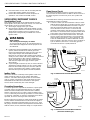
Check the flame sensing current from the sensor to the
S8701/S8702 control as follows:
1. Connect a meter (dc microammeter scale) in series
with the flame signal wire as shown in figures 4 and
5. Use the Honeywell W136A test meter or equiva-
lent. Disconnect the flame sense wire from the
sense terminal on the control. Connect the red
(positive) meter lead to the flame sense terminal on
the control. Connect the black (negative) meter lead
to the flame sense wire that goes to the flame rod.
2. Restart the system and read the meter. The flame
sensor current must be at least 1.0 µA and steady.
If the reading is less than 1.0 µA or unsteady , see
LOW OR UNSTEADY FLAME CURRENT section,
below. If flame is present at sensor and a reading of
0 µA is obtained, check for a secondary ground
connection to the 24 V (GND) terminal.
Fig. 6. S8701 Flame Current Measurement.
ALARM
VALVE
(GND)
SPARK
SENSE
RED (+)
BLACK (–)
MULTIPURPOSE
METER
1.2 µA dc MINIMUM (AND STEADY)
M16236A
FLAME
SENSOR
BURNER
Fig. 7. S8702 Flame Current Measurement.
(See also S8701 Fig. 4).
GND
SENSE 2
VALVE (GND)
BURNER
(GND)
24 Vac (GND)
24 Vac
RED (+)
BLACK (–)
MULTIPURPOSE METER
1.2 µA dc MINIMUM
(AND STEADY)
M16268A
FLAME
SENSOR
BURNER

69-1174
9
S8701/S8702 DIRECT SPARK IGNITION CONTROLS
CHECK BURNER FLAME CONDITION
NOISY LIFTING FLAME
BURNER
WAVING FLAME
SMALL BLUE FLAME
LAZY YELLOW FLAME
GOOD RECTIFYING FLAME
1 IN. (25.4 MM)
1/4 TO 1/2 IN. (6.4 TO 12.7 MM)
M18055
CHECK FOR:
• HIGH GAS PRESSURE
• EXCESS PRIMARY AIR
OR DRAFT
CHECK FOR:
• POOR DRAFT
• EXCESS DRAFT
• HIGH VELOCITY OR
SECONDARY AIR
INSTALL SHIELD IF NECESSARY.
CHECK FOR:
• CLOGGED PORTS OR
ORIFICE FILTER
• WRONG SIZE ORIFICE
CHECK FOR
LACK OF AIR FROM:
• DIRTY PRIMARY
AIR OPENING
• LARGE PORTS
OR ORIFICES
Low or Unsteady Flame Current
If the current to the S8701/S8702 is less than 1.0 µA or is
unsteady, check the burner flame, flame sensor location
and electrical connections as follows:
Burner Flame
The flame sensor must be constantly immersed in flame.
Check burner flame conditions as shown in Fig. 8.
Flame Sensor
The flame signal is best when about 1 inch. (25 mm) of
flame rod is immersed in the burner flame. A bent flame
rod, bent mounting bracket or cracked ceramic insulator
can affect flame signal. Replace flame sensor if necessary.
Electrical Connections and Shorts
Connections at the flame sensor must be clean and tight. If
wiring needs replacement, use moisture resistant no. 18
AWG wire rated for continuous duty up to 105°C (221°F).
Fig. 8. Check Burner Flame Conditions.
Checkout After Service
Perform the following steps before leaving the job (de-
scribed in the CHECKOUT section).
• START SYSTEM
• TRIAL FOR IGNITION PERIOD CHECK
• SAFETY LOCKOUT RESET
Also perform any other checks recommended by the
heating appliance manufacturer if system components
other than the S8701 or S8702 were serviced.
TROUBLESHOOTING GUIDE
Start the system by setting the thermostat or temperature
control to call for heat. Observe the system response and
establish the type of malfunction or deviation from normal
operation by using the troubleshooting guide. After any
maintenance or repair, the troubleshooting sequence
should be repeated until normal system operation is
obtained.

69-1174
10
S8701/S8702 DIRECT SPARK IGNITION CONTROLS
START
SPARK STOPS WHEN
BURNER IS LIT
SYSTEM RUNS UNTIL
CALL FOR HEAT ENDS
CALL FOR HEAT ENDS:
SYSTEM SHUTS OFF
TROUBLESHOOTING ENDS
TURN THERMOSTAT TO
CALL FOR HEAT
TURN GAS SUPPLY OFF.
POWER TO UNIT
(24 VAC NOMINAL)
SAFE START CHECK OK.
J, K, L, AND M MODELS
PREPURGE DELAY.
CHECK LINE VOLTAGE POWER, LOW VOLTAGE TRANSFORMER, LIMIT CONTROLLERS,
THERMOSTATS AND WIRING. ALSO, AIR PROVING SWITCH ON PREPURGE
SYSTEMS (SEE FIGS. 4 AND 5).
UNIT LOCKS OUT ON POWER UP. CHECK FOR FLAME AT EACH BURNER. IF FLAME
IS PRESENT, SHUT OFF GAS SUPPLY AND REPLACE GAS CONTROL. IF NOT, REPLACE
IGNITION CONTROL.
SPARK ACROSS IGNITER OR
IGNITER/SENSOR GAP.
NO PREPURGE DELAY. REPLACE J, K, L, OR M UNIT.
M18059
NOTE: BEFORE TROUBLESHOOTING, FAMILIARIZE YOURSELF
WITH THE START-UP AND CHECKOUT PROCEDURE.
• TURN OFF GAS SUPPLY.
• PULL IGNITION LEAD
AND CHECK SPARK AT
SPARK TERMINALS.
SPARK OKAY?
• CHECK IGNITION CABLE, BURNER GROUND WIRING, CERAMIC INSULATOR AND GAP,
AND CORRECT.
• CHECK BOOT OF THE IGNITION CABLE FOR SIGNS OF MELTING OR BUCKLING. TAKE
PROTECTIVE ACTION TO SHIELD CABLE AND BOOT FROM EXCESSIVE TEMPERATURES.
• CHECK FOR 24 VAC ACROSS VALVE AND VALVE TERMINALS DURING TRIAL FOR
IGNITION PERIOD. IF NO VOLTAGE, REPLACE UNIT.
• Q347, Q354 OR Q366 MAY BE OUT OF POSITION.
• CHECK ELECTRICAL CONNECTIONS BETWEEN UNIT AND GAS CONTROL. IF OKAY,
REPLACE GAS CONTROL.
NOTE: IF UNIT GOES INTO LOCKOUT, RESET SYSTEM.
• CHECK CONTINUITY OF SENSOR CABLE(S) AND GROUND WIRES.
NOTE: IF GROUND IS POOR OR ERRATIC, SHUTDOWNS MAY OCCUR OCCASIONALLY
EVEN THOUGH OPERATION IS NORMAL AT TIME OF CHECKOUT.
• CHECK FOR EXCESSIVE HEAT AT SENSOR INSULATOR(S)
(TEMPERATURE ABOVE 1000 °F (538 °C) CAUSES SHORT TO GROUND).
• IF CHECKS ARE OKAY, REPLACE UNIT.
NOTE: IF UNIT GOES INTO LOCKOUT, RESET SYSTEM.
• CHECK CONTINUITY OF SENSOR CABLE(S) AND BURNER GROUND WIRES.
• CHECK THAT BURNER FLAME COVERS ALL ELECTRODES (ON BOTH BURNERS IF S8702).
• CHECK 24V GROUND CONNECTION TO BURNER.
• IF CHECKS ARE OKAY, REPLACE UNIT.
• CHECK FOR PROPER TEMPERATURE CONTROLLER OPERATION.
• REMOVE VALVE LEAD AR UNIT; IF VALVE CLOSES, RECHECK TEMPERATURE
CONTROLLER AND WIRING; IF NOT, REPLACE GAS CONTROL.
REPLACE UNIT
REPEAT PROCEDURE UNTIL TROUBLE FREE OPERATION IS OBTAINED.
NOTES: B, D, J, AND K MODELS GO THROUGH ONE (1) TRIAL FOR IGNITION PERIOD BEFORE LOCKOUT.
E, F, L, AND M MODELS GO THROUGH THREE (3) TRIAL FOR IGNITION PERIODS WITH A 30 SECOND
INTERPURGE PERIOD BETWEEN TRIAL FOR IGNITION PERIODS BEFORE LOCKOUT AND THEN RETRY AUTOMATICALLY
AFTER ONE (1) HOUR.
LOCKOUT = VALVE CLOSED PLUS SPARK OFF PLUS ALARM ACTIVATED PLUS LED ON STEADY.
S8702 MODELS SPARK AND SENSE FLAME ON TWO SEPARATE BURNERS.
FLAME MUST BE SENSED ON BOTH BURNERS DURING TRIAL FOR IGNITION ON THE UNIT WILL LOCKOUT.
MAIN BURNER(S) LIGHTS
NO
YES YES
YES
YES
YES
YES
YES
YES
YES
YES
NO
NO
NO
NO
NO
NO
NO
NO
Fig. 9. S8701/S8702 Direct Spark Ignition System Troubleshooting Guide

69-1174
11
S8701/S8702 DIRECT SPARK IGNITION CONTROLS

Home and Building Control
Honeywell Limited-Honeywell Limitée
155 Gordon Baker Road
North York, Ontario
M2H 3N7
69-1174 L.C. 4-99 Printed in Mexico
Home and Building Control
Honeywell Inc.
Honeywell Plaza
P.O. Box 524
Minneapolis, MN 55408-0524
www.honeywell.com
-
 1
1
-
 2
2
-
 3
3
-
 4
4
-
 5
5
-
 6
6
-
 7
7
-
 8
8
-
 9
9
-
 10
10
-
 11
11
-
 12
12


Ask a question and I''ll find the answer in the document
Finding information in a document is now easier with AI
Related papers
-
Honeywell S8670 User manual
-
-
-
-
-
-
-
-
Other documents
-
PVI Industries Controls Owner's manual
-
American Water Heater BCL User manual
-
Johnson Controls G861 Series Technical Bulletin
-
Garland 200 User manual
-
Beckett GeniSys™ 7586 24V Gas Burner Control User manual
-
 Honeywell Home S9200U1000 Installation guide
-
Empire FAN TYPE VENTED WALL FURNACE FAW-55IP User manual
-
Reznor RECB User manual
-
-
