Page is loading ...

IMPORTANT: PLEASE READ BEFORE ATTEMPTING TO
I
NSTALL MAGNETIC LOCK
A. Handle the equipment with care, damaging the mating
s
urface of the magnet or armature plate may reduce locking
efficiency.
B. The magnet mounts rigidly to the door frame. The armature
plate mounts to the door with hardware. The kit provided
allows the armature to pivot about its center to compensate
for door wear and misalignment.
C. Template use must take place with the door
in its normally closed position.
D. Firmly tighten all screws.
ABCDEFGH
8.0 1.75 2.9 .81 1.0 .4 .5 .7
MAGNET DIMENSIONS (INCHES)
ABCDEFGH
203.2 44.45 73.66 20.57 25.4 10.16 12.7 19.05
MAGNET DIMENSIONS (MM)
BLIND NUT
HEADER
DOOR
HEAD
3/8" (US) OR 9.5MM
(METRIC) HOLE
B
G
H
F
CABLE
D
E
A
C
TAMPER
CAP
GOLD
W
ASHER
SOCKET CAP SCREW
1/4-20 X 3"
(US VERSION)
6MM-1MM X 75MM
(METRIC VERSION)
Fig. 2 ARMATURE DIMENSIONS AND ASSEMBLY
Important: Armature plate must be able to float
freely. Do not over tighten. The armature
plate will automatically adjust to the
proper position with the magnet.
Fig. 1 STANDARD MAGNET DIMENSIONS
AND ASSEMBLY
A
B
C
D
E
F
F
ABCDEF
6.0 2.75 .5 1.37 3 2.25
152.4 69.9 12.7 34.8 76.2 57.2
ARMATURE DIMENSIONS
(IN.)
(MM)
INSTALLATION INSTRUCTIONS
1584 - 1587 Series Electromagnetic Locks
FOR ASSISTANCE CONTACT SARGENT AT 800-810-WIRE (9473) or www.sargentlock.com
1
A7361A
Copyright © 2009, Sargent Manufacturing Company, an ASSA ABLOY Group
company. All rights reserved. Reproduction in whole or in part without the
express written permission of Sargent Manufacturing Company is prohibited.

Fig. 4.1 COLLAPSING THE BLIND NUTS
Four holes must be drilled for the mounting screws, and a
1/2” (12.7 mm) diameter wire-way hole should be drilled for
hook-up. For proper strength, the 1/4-20 (6 mm) mounting
machine screws must be secured by the special blind finishing
nuts. The nuts will work on any thickness metal header and are
used as follows: A 3/8” (10mm) hole is drilled according to the
template for each nut. The nut is then pressed up into the hole
and lightly seated with a hammer tap so its knurl engages. The
nut is then pre-collapsed inside the header.
TAMPER CAPS
STOP
HEADER
DOOR
ARMATURE
HEADER BRACKET
I
F FRAME IS TOO
NARROW
S
TOP FILLER
PLATE IF STOP
IS TOO NARROW
WASHERS
STACK (2)
SEX
BOLT
MAGNET
1/4-20 (6 mm)
MOUNTING SCREWS
3'' (76 mm) LENGTH.
O
THER LENGTHS
MAY BE REQUIRED
DEPENDING ON DOOR
BLIND NUTS
NARROW
FRAME
.75"
2.5"
(57.15 mm)
(19mm)
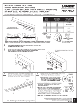
Fig. 4 TYPICAL MOUNTING FOR PUSH APPLICATION
MOUNTING THE MAGNET
The magnet mounts in the door frame header with four socket
cap machine screws for metal frames or wood screws for wood
frames. In mounting the Electromagnet, 6 conditions must
be followed:
— The frame header must present a flat surface for the
Magnet to mount to.
— The frame area selected must be reinforced to yield a properly
secure installation.
— The magnet face must be parallel to the armature.
— The magnetic poles (three metal bars on the Electromagnet),
must be centered on the armature.
— The magnet must make solid contact with the armature
but still allow the door to close properly.
— The direction of door opening must pull the armature
directly away from the magnet rather than sliding it away.
Electromagnets hold only weakly in the shear direction of pull.
Taking these points in order, the first is satisfied if the frame
presents a flat surface wide enough for the Magnet. If not, the
use of stop filler plates and/or header brackets available from
SARGENT can usually resolve the problem. Figure 4 shows the
typical use of these two accessories. 2-1/2” (63.5MM) are
required from the door to the rear of the Magnet for proper
mounting (as shown in the drawing).
The issue of frame strength must be considered in selecting
vertical or horizontal mounting. On aluminum headers the
horizontal extrusion is weak and can be snapped off so vertical
mounting would obviously be preferred. It is also possible to
reinforce the header by adding a steel plate. The installer must
avoid mounting the magnet to a wobbly or weak support or the
intrinsic security of the lock will be diminished.
Once a flat surface has been prepared for the Magnet, it must
be positioned so that its face is parallel to the armature (and
door). The magnetic poles must be centered on the armature,
and the door must close properly with the Magnet making firm
contact to the armature. When the Magnet has been
experimentally positioned so that these criteria are met, it’s
ready for mounting.
HEADER
TOOL
BLIND NUT
COLLAPSES WHEN CAP SCREW
IS TURNED WITH ALLEN WRENCH
WHILE TOOL IS HELD FAST
WITH BOX WRENCH
WHILE TURNING WITH ALLEN
WRENCH, PRESS IN TO KEEP
NUT SEATED IN HEADER
HOLD WITH WRENCH OR
VISE GRIP WHILE TURNING
CAP SCREW
DRILL 3/8" (9.5MM)
HOLE PRESS IN BLIND
NUT AS SHOWN
KNURL
CAP SCREW 1/4-20 X 1" (US) OR
6MM-1MM X 25MM (METRIC)
TWO FLAT WASHERS
IF SCREW IS STIFF TO TURN,
ADD LUBRICANT TO WASHERS
FLATHEAD SCREW
(US VERSION)
5/16-18 X 1 3/4"
(METRIC VERSION)
8mm-1.25mm X 40mm
2 X RUBBER
WASHERS
DOOR
EXPLOSION SHOWS CONVENTIONAL ARMATURE MOUNTING
(OUTSWINGING DOOR - PUSH APPLICATION)
WHITE PLASTIC
B
USHING
W
HITE PLASTIC
BUSHINGS
LATCH SIDE OF THE DOOR
1
/4" X 1 1/4"
ROLL PINS
SEXBOLT
1/2"
12.7MM
Fig. 3 ARMATURE MOUNTING
The armature should be mounted before the
magnet on the upper corner of the door according
to template. Final positioning of the armature is
dictated by the desired position of the magnet.
T
he armature must be centered on the magnetic
poles (3 bars). Roll pins furnished with the arma-
ture should then be hammered into the armature.
The armature is secured by the center armature
mounting screw.
Two flexible washers are then placed between the
a
rmature and the door with the armature mount-
ing screw passing through the washers to provide
flexibility.
Do not place the washers around the roll pins. The
roll pins should "float" in their holes and not bind.
Their only purpose is to prevent the armature from
rotating.The armature is secured to the door via
the supplied sex bolt.
2
Copyright © 2009, Sargent Manufacturing Company, an ASSA ABLOY Group
company. All rights reserved. Reproduction in whole or in part without the
express written permission of Sargent Manufacturing Company is prohibited.
A7361A

3
Copyright © 2009, Sargent Manufacturing Company, an ASSA ABLOY Group
company. All rights reserved. Reproduction in whole or in part without the
express written permission of Sargent Manufacturing Company is prohibited.
A7361A
STOP
(2) #14 HEX
S
HEET METAL
SCREW
Z BRACKET
DOOR
MAGNALOCK
DOOR
HEADER
M
OUNTING
SCREWS
W
ASHERS (2)
USE 1" MOUNTING
SCREW SUPPLIED
W
ITH Z BRACKET
ARMATURE
SEX BOLT
(
DRILL 1/2"
13 mm HOLE)
CAP SCREW
5
/16"-18
(8mm-1.25mm)
DRESS COVER SLIDES ON
LAST WITH OPEN SIDE UP
AND IS ATTACHED WITH
SUPPLIED DOUBLE STICK TAPE
T
-NUT REQUIRES
3/8" (10 mm) DIA HOLE
I
N BRACKET AND
ACCEPTS STRIKE
MOUNTING SCREW.
R
OLL PIN PLASTIC
BUSHINGS REQUIRE 1/2"
(
13 mm) HOLES AND MUST
BE SHORTENED TO WORK
I
N Z BRACKET.
Fig. 5 FACE MOUNT MAGNET DIMENSIONS
AND ASSEMBLY
A
B
C
D
E
F
G
G
GOLD WASHER
BLIND NUT
CABLE EXIT
TAMPER CAP
(US VERSION)
1/4-20 X 2 1/2"
(METRIC VERSION)
6mm-1mm X 60mm
DOUBLE DOOR MOUNTING
It is very common to use electromagnetic locks on double doors as most electromechanical locks cannot be utilized. In some cases
one of the door leaves is inactive so that only one leaf is used and this is secured by a single electromagnetic lock. If both leaves
are to be active, 2 electromagnetic locks can be used. For the most attractive installation, they should be butted together but if
obstructions exist in the header that interferes with mounting, the magnets can be separated and covered with an 18" dress cover
for push applications.
Fig. 4.2 TYPICAL MOUNTING FOR A PULL
APPLICATION WITH Z BRACKET
In cases where the electromagnetic lock must be
mounted on the inswinging side of the door to
p
rotect it from physical assault, the magnet body is
mounted flush on the wall above the door frame and
a
“Z” bracket is affixed to the door which positions
the armature in front of the magnet (part #15-2114
or Z bracket). SARGENT’s 1586 and 1587
electromagnetic locks have mounting holes through
the face of the magnet and wire that exits to the rear
for pull mounting applications. Figure 5 shows this
configuration. Note that when the roll pin bushings
are used, they protrude through the Z bracket and
interfere with the Z bracket cover. Roll pin bushings
m
ust be used to provide insulation. They should be
cut with a hacksaw to function in the bracket.
ABCDEFG
8.0 1.75 2.9 .5 1.48 .5 .45
MAGNET DIMENSIONS (INCHES)
ABCDEFG
203.2 44.45 73.66 12.7 37.59 12.7 11.43
MAGNET DIMENSIONS (MM)

Fig. 7 STANDARD WIRING REQUIREMENTS
For operation, DC voltage (24 or 12VDC) must be provided to the lock. The red
wire receives +12VDC or +24VDC, and the black wire, 0V (negative). If the
lock is connected with reverse polarity, it will not function at all. The voltage
source must be regulated, filtered DC. Half wave pulsating DC generated by a
transformer and single diode will not properly operate the electromagnetic lock.
An exact voltage level is not necessary. However less than standard voltage
will proportionately reduce holding force but will cause no harm.
The current
draw is 125 mA for 24V versions or 250 mA for 12V.
Fig. 9 USE OF DRESS COVERS
Dress covers are metal stampings, which slip over the magnet body and are
affixed with permanent double stick tape (supplied). The dress cover accomplishes
three functions: it makes for a more attractive installation by concealing the strike
plate and mounting holes. Second, the cover provides an extra degree of tamper
proofing and finally it allows easy alteration of the finish for architectural compati-
bility. Dress covers are available on 28, EB and ED.
Double dress covers are also available for installations on double doors. In this
case, the cover fits over two locks so long as they are not separated by more than
2”. Double dress covers have all the advantages mentioned above and in addition
produce the appearance of a single device which inside is really two. Double dress
covers are available on 28, EB and ED.
Fig. 8 ELECTROMAGNETIC LOCKS
All SARGENT electromagnetic locks provide a dry SPDT output which
changes state when the lock is reporting secure (1 Amp @ 30 VDC
maximum). This is accomplished by conducting the input power of the lock
through the strike and employing it to energize an internal SPDT relay. The
white wire is the sensor relay common. Green is closed to white when the
lock is secure and Orange is closed to white when the lock is not secure. If
the sensor is used on a metal door, the strike should be insulated from the
door by utilizing the supplied insulating hardware.
RED
BLK
GREEN
WHITE
POWER
SUPPLY
+
WHITE AND GREEN WIRES PROVIDE ISOLATED CLOSURE
WHEN LOCK IS SECURE. ORANGE AND WHITE ARE CLOSED
WHEN LOCK IS NOT SECURE (AS SHOWN ABOVE).
ORANGE
1584-1587
MAGNET
SWITCH
CONTROL
SYSTEM WIRING DIAGRAM
+
–
3510
24VDC REG.
P
OWER
SUPPLY
N.C. F.A. CONTACTS
1584 - 1587
24VDC
MAGNET
DRESS
COVER
Fig. 6 WOOD FRAME MOUNTING
With a wooden frame, long wood screws may be used to mount the electromagnetic lock. If, however, the frame is not solid enough to
secure the electromagnetic lock adequately, a wood frame bracket available from SARGENT may be used (part #15-2113).
The electromagnetic lock mounts to the bracket via machine screws and the bracket permits wood screws (furnished) to penetrate
m
ore deeply into the header (see Figure 6). Presently, the brackets are
not available in metric threaded versions so they must be mated with US
t
ype screws.
STEEL HEADER FILLED WITH
C
ONCRETE MOUNTING
The blind nuts function normally despite the presence of concrete but
a problem can occur in pulling the hook up wires. To help,
SARGENT offers the concrete header bracket (part #15-2113) which
permits a range of techniques (see Figure 6). The center of the bracket
forms a splice chamber if it’s difficult to pull the wires back into the head-
er. Alternately the wires may be pulled through the edge of the bracket
by drilling a hole if it’s impractical to drill the concrete.
SPLICE
CHAMBER
MAGNET SCREWS INTO
T
APPED HOLES (4 PLACES)
3/8"
S
HEET METAL SCREWS
USED FOR CONCRETE
HEADER BRACKET
WOOD SCREWS
U
SED FOR WOOD
FRAME
SCREWS MOUNT BRACKET TO HEADER
THROUGH 8 COUNTERSUNK HOLES
Fig. 6 WOOD FRAME AND CONCRETE HEADER BRACKET
4
Copyright © 2009, Sargent Manufacturing Company, an ASSA ABLOY Group
company. All rights reserved. Reproduction in whole or in part without the
express written permission of Sargent Manufacturing Company is prohibited.
A7361A
/