Page is loading ...

Features
Photoelectric transmitter and receiver are
combined in a single, compact housing:
An infrared beam is reflected from a matching prism
with the reflected light analyzed by an on-board
microprocessor providing area smoke detection
Two models are available:
– Model 50RU is for 15 ft to 160 ft (5 m to 50 m)
– Model 100RU is for 160 ft to 330 ft (50 m to 100 m)
Each model includes the matching prism reflector(s),
a wall mounting bracket, and a calibrated test filter
UL listed to Standard 268
Microprocessor controlled operation includes:
Easy setup and alignment with three selectable alarm
thresholds of 25%, 35%, or 50% beam obscuration (can
be mounted horizontally or vertically)
Operation at either 12 VDC or 24 VDC
Alarm latching or alarm auto-reset
Automatic gain control
Separate alarm and trouble contacts
Applications:
Open areas where ceiling height exceed 25ft (7.6 m)
(warehouses, hotel atriums, industrial plants, and school
gymnasiums)
Public areas where cosmetics are of prime importance
and detector heads need to be small and unobtrusive
(shopping malls, libraries, theaters, and churches)
Benefits:
Reduces installation costs where 6 or more spot
detectors are required in a single area
Optional remote test station mounts at ground level and
reduces service time by testing without site disruption
Optional Accessories:
Surface mount matching backbox
Extended alignment bracket
Remote Test Station
Description
Single Unit Design. A single unit houses both an
infrared transmitter and receiver. The transmitter signal is
reflected by a matching prism back to the receiver where
the internal microprocessor analyzes it for the presence of
smoke. An alarm condition is determined when the
selected sensitivity level is reached.
Mounting. Detectors are mounted with the beam
projecting between 1 ft (305 mm) and 2 ft (610 mm)
below, and parallel to the ceiling. Lateral detection may
be up to 30 ft (9.144 m) on either side of the beam,
providing a maximum total coverage area of up to
19,800 ft
2
(60 ft x 330 ft or 18.288 m x 100 m).
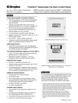
50RU/100RU Reflective Beam Detector (shown without
wall mount bracket) and LLC Remote Test Station
Description (Continued)
Application Note. Reflective beam smoke detectors may
not be suitable for areas with highly reflective surfaces.
Separate transmitter/receiver models may be required.
Engineering Specification
The projected beam type smoke detector shall be a 4-wire
12/24 VDC device to be used with a UL Listed separately
supplied 4-wire control panel. Unit shall be listed to
UL 268 and shall consist of an integrated transmitter and
receiver. The detector shall operate between a range of
15 ft to 330 ft (5 m to 100 m). The temperature range of
the beam shall be -4° F to 131° F (-20° C to +55° C)
[UL 268 listed temperature range is 32° F to 100° F (0° C
to 38° C)]. The beam detector shall feature automatic gain
control which will compensate for gradual signal
deterioration from dirt accumulation on the lenses. The
unit shall include a wall mounting bracket. Testing shall
be carried out by using a calibrated obscuration test filter.
The Reflective beam type smoke detector shall be a Fire
Fighting Enterprises 50RU (160 ft/50 m) or 100RU
(330 ft/100 m).
Beam Detector Spacing
On smooth ceilings, up to 60 ft (18.288 m) between
reflective beams and not more than one-half the spacing
between a reflective beam and a sidewall. Other spacing
may be used depending on ceiling height, airflow
characteristics, and response requirements.
Refer to NFPA 72 and Installation Instructions supplied
with unit for further information.
* Listings are by Fire Fighting Enterprises. Refer to CSFM 7260-1508:102; and MEA 70-02-E.
This product was not approved by FM as of document revision date.
Non-Addressable Initiating Peripherals
UL, ULC, CSFM Listed; Reflective Beam Smoke Detectors
MEA (NYC) Acceptance* Fire Fighting Enterprises Models 50RU and 100RU
S4098-0040-2 12/2011

Ordering Number Model Description
0206.02 50RU Reflective beam smoke detector; 160 ft (50 m) maximum distance
0206.03 100RU Reflective beam smoke detector; 330 ft (100 m) maximum distance
0400-01 LLC
Remote Test Station/Low Level Controller (0400); single gang mount; provides remote Power-on
LED, Alarm LED, and remote Alarm Test
23901.01 23901 Replacement Prism; Note; Model 100RU uses 4 prisms, Model 50 RU uses 1 prism
0608.01 0608 Surface mount matching backbox
0893.01 0893 Extended Alignment Bracket, allows up to +/- 45° adjustment for either detector or prism
1000-020 NA Optional Protective Wire Cage
Internal Ordering Note: These products can be found in Job Design under the Air Products OP category OPFFE.
Construction Specifications
Housing Flame Retardant ABS; IP rating = IP50
Finish Grey/Black
Dimensions, housing only 8-1/4” H x 4-3/4” W x 4-1/2” D (210 mm x 121 mm x 114 mm)
Dimensions, with bracket 8-1/4” H x 5” W x 4-3/4” D (210 mm x 126 mm x 121 mm)
Prism Dimensions
3-15/16” square x 3/8” D (100 mm x 9.5 mm) each;
one is used by the Model 50RU; four are used by the Model 100RU
Manufacturer Fire Fighting Enterprises (A Halma Group Company); website: www.ffeuk.com/
Electrical Specifications
Input Voltage 10.2 to 30 VDC
Standby Current 4 mA @ 24 VDC
Alarm Current 15 mA @ 24 VDC
Alarm and Trouble Relays Dedicated, separate Form C relays, rated 1 A @ 30 VDC resistive
Wiring Method Pluggable connector with attached wire leads
Optical Wavelength 880 nm
Operating Specifications
Startup Time 10 seconds
Reset Time 5 seconds maximum
Sensitivity 25%, 35%, or 50% obscuration
Operating Distance
50RU 15 ft to 160 ft (5 m to 50 m)
100RU 160 ft to 330 ft (50 m to 100 m)
Status Indicators
Alarm = Red LED
Trouble = Amber LED
Alarm Types Select latching or non-latching operation
Trouble Conditions Improper setup alignment; 90% or more obscuration
UL Listed Temperature Range 32° F to 100° F (0° C to 38° C)
Operating Temperature Range -4° F to 131° F (-20° C to 55° C)
Relative Humidity 10 to 93% RH, non-condensing
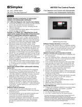
Beam Detector
on Surface Mount
Backbox, shown with
optional 1000-020
Wire Cage
Extended
Alignment
Bracket
Prism
Reflector
TYCO, SIMPLEX, and the product names listed in this material are marks and/or registered marks. Unauthorized use is strictly prohibited. NFPA 72 and National Fire Alarm Code
are trademarks of the National Fire Protection Association (NFPA).
Tyco Fire Protection Products • Westminster, MA • 01441-0001 • USA S4098-0040-2 12/2011
www.simplexgrinnell.com
© 2011 Tyco Fire Protection Products. All rights reserved. All specifications and other information shown were current as of document revision date and are subject to change without notice.
Specifications
Ordering Information
Additional Product Details (not shown to scale)
/