Page is loading ...

63296 Powell Butte Hwy • Bend, OR 97701 • (541) 318-6060 • iFlyEi.com
Read this manual before installing this
instrument. It contains information that
may aect your decision to install this
product and/or the safety of your aircraft.
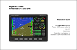
CGR-30P
Operating Instructions
OI 0702131 - Rev. B: 7/2/13
The CGR-30P is an FAA-Approved Primary Replacement
for Engine and Aircraft System Instruments
**

Blank Page

Important Notice
***** MUST READ *****
If you think it is not important to read this manual, you’re wrong! This manual
contains important operating information that may affect the safety of you, your
aircraft and passengers.
Read the Warranty / AgreementRead the Warranty / Agreement
Read the Warranty / AgreementRead the Warranty / Agreement
Read the Warranty / Agreement. There is information in the Warranty/Agreement that may alter your
decision to install this product. If you do not accept the terms of the Warranty / Agreement, doIf you do not accept the terms of the Warranty / Agreement, do
If you do not accept the terms of the Warranty / Agreement, doIf you do not accept the terms of the Warranty / Agreement, do
If you do not accept the terms of the Warranty / Agreement, do
not install this productnot install this product
not install this productnot install this product
not install this product. This product may be returned for a refund. Contact Electronics International
inc. for details.
By installing this product, the aircraft owner/pilot and installer agree to hold Electronics International Inc.
harmless and in no way responsible for monetary compensation, including punitive damages for any
incident, harm and/or damage associated with this product. If you do not agree to the above, DO NOTDO NOT
DO NOTDO NOT
DO NOT
INSTALL THIS PRODUCT.INSTALL THIS PRODUCT.
INSTALL THIS PRODUCT.INSTALL THIS PRODUCT.
INSTALL THIS PRODUCT. This product may be returned for a refund. Contact Electronics Interna-
tional inc. for details.
The pilot mustmust
mustmust
must
understand the operation and limitations of this product before flying the aircraft. Do not
allow anyone to operate the aircraft that does not know how to properly interpret and operate this product.
Keep the Operating Instructions in the aircraft at all times. If you do not thoroughly understand the
operation of this product, contact a knowledgeable flight instructor for training.
The ability for this product to respond to an engine or aircraft system anomaly is directly related to how
that anomaly affects the reading of the function(s) being monitored (i.e.; if an engine fire does not affect
the EGT or CHT, the EGT and CHT readings will not change).
This instrument only displays the parameters for the function(s) being monitored. The pilot is responsible
for interpreting the data and determining if an engine or aircraft system anomaly exists. When using this
instrument, the pilot’s diagnostic ability is limited to his/her interpretation of the displayed data and the
their observation skills. To improve these skills the pilot should seek training from a flight instructor.
If after reading this manual you do not have the knowledge to interpret the displayed data to operate the
aircraft safely or to detect engine and/or aircraft system problems, contact a knowledgeable instructor for
training prior to flying the aircraft with this instrument.
If you detect a problem using this instrument, it is your responsibility to take appropriate action to ensure
the safety of the flight. Practice simulating problems to build your skills and to improve your understand
of the relationships between problems and their affects on the displayed data. To ensure you are taking
appropriate action, contact a knowledgeable flight instructor for training. Inappropriate action can lead to
aircraft and/or engine damage, personal injury or death.
This manual does not make any recommendations as to specific operating parameters or controlling
methods. Check the airframe and/or engine manufacturer’s recommendations to properly operate the
aircraft systems and engine. It is the pilot’s responsibility to operate the engine and aircraft safely.
Notice Page 1

Important Notice
***** MUST READ *****
It is possible for any instrument to fail thereby displaying inaccurate high, low or jumpy readings.
Therefore, you mustmust
mustmust
must be able to recognize an instrument failure and you mustmust
mustmust
must be proficient in operating
your aircraft safely in spite of an instrument failure. If you do not have this knowledge, contact the FAA
or a knowledgeable flight instructor for training prior to flying the aircraft with this instrument.
Electronics International Inc. is not liable or responsible for a pilot’s action or any situation that results in
personal injury, property damage, missed commitments, lack of use of an aircraft or any expenses
incurred due to: product failure, inaccuracy in displayed data or text files, display or display format
issues, software bugs or problems, upgrade or customization issues, misinterpretation of the display,
warning and/or limit settings, calibration problems, installation issues (leaks, mis-wiring, obstructions,
damage to aircraft or components, incorrect installation of any parts, wrong parts, parts that don’t fit,
etc.) or any other issues related to the installation or operation of this product. All of the above are
solely the pilot’s and/or installer’s responsibility. The pilot mustmust
mustmust
must
understand the operation of this prod-
uct before flying the aircraft. The pilot must not allow anyone to operate the aircraft that does not know
the operation of this product. The pilot must keep the instrument Operating Instructions in the aircraft at
all times.
Set a unique password to protect all of the calibration and setup data in the CGR-30P. If setup or calibra-
tion data is inadvertently or improperly changed, you could get inaccurate readings that may lead to
improper operation of the aircraft or engine. This could result in engine damage and/or an emergency
situation.
Before flying the aircraft verify that the instrument markings displayed on the CGR are accurate with
your POH for every function displayed on the CGR.
The CGR must be calibrated to the aircraft fuel system and the CGR's accuracy must be verified before
flying the aircraft.
Fuel Level Accuracy Limitations:Fuel Level Accuracy Limitations:
Fuel Level Accuracy Limitations:Fuel Level Accuracy Limitations:
Fuel Level Accuracy Limitations:
The accuracy limitations of the CGR are listed below. It is the pilot/owner’s obligation to makeIt is the pilot/owner’s obligation to make
It is the pilot/owner’s obligation to makeIt is the pilot/owner’s obligation to make
It is the pilot/owner’s obligation to make
anyone flying the aircraft aware of these limitations.anyone flying the aircraft aware of these limitations.
anyone flying the aircraft aware of these limitations.anyone flying the aircraft aware of these limitations.
anyone flying the aircraft aware of these limitations.
1. Angle of Attack -1. Angle of Attack -
1. Angle of Attack -1. Angle of Attack -
1. Angle of Attack - The CGR must be calibrated with the aircraft in a cruise angle of attack. If the
aircraft is in an angle of attack other than cruise, the CGR may display inaccurate fuel levels (depending
on the mounting location and type of sensor used). If your aircraft does not sit at a cruise angle of attack
when on the ground, it may not display accurate fuel levels. Test your aircraft at different anglesTest your aircraft at different angles
Test your aircraft at different anglesTest your aircraft at different angles
Test your aircraft at different angles
of attack to determine how the CGR fuel level readings are affected.of attack to determine how the CGR fuel level readings are affected.
of attack to determine how the CGR fuel level readings are affected.of attack to determine how the CGR fuel level readings are affected.
of attack to determine how the CGR fuel level readings are affected.
2. Full Fuel Readings -Full Fuel Readings -
Full Fuel Readings -Full Fuel Readings -
Full Fuel Readings - As a tank is filled the fuel sensor may be unable to detect the fuel entering
Notice Page 2

Important Notice
***** MUST READ *****
the upper corners of the fuel tank. If this is the case with your sensor, the CGR may display fuel levels
lower than the actual fuel in the tanks when the tanks are full. When the fuel level drops to a point
where the fuel sensor starts to detect a change, the displayed fuel level should be accurate. Check the Check the
Check the Check the
Check the
accuracy of your system by comparing the displayed fuel levels on the CGR to the fuelaccuracy of your system by comparing the displayed fuel levels on the CGR to the fuel
accuracy of your system by comparing the displayed fuel levels on the CGR to the fuelaccuracy of your system by comparing the displayed fuel levels on the CGR to the fuel
accuracy of your system by comparing the displayed fuel levels on the CGR to the fuel
levels listed in the flight manual at each fill up.levels listed in the flight manual at each fill up.
levels listed in the flight manual at each fill up.levels listed in the flight manual at each fill up.
levels listed in the flight manual at each fill up.
3. Low Fuel Readings -3. Low Fuel Readings -
3. Low Fuel Readings -3. Low Fuel Readings -
3. Low Fuel Readings - Do not rely on the CGR to determine the fuel level in the tankDo not rely on the CGR to determine the fuel level in the tank
Do not rely on the CGR to determine the fuel level in the tankDo not rely on the CGR to determine the fuel level in the tank
Do not rely on the CGR to determine the fuel level in the tank
for an indicated tank level below 1/8for an indicated tank level below 1/8
for an indicated tank level below 1/8for an indicated tank level below 1/8
for an indicated tank level below 1/8. You should always fly the aircraft in such a manner as to
at least maintain the FAA minimum fuel requirements in the aircraft at all times. Depending on theDepending on the
Depending on theDepending on the
Depending on the
mounting location and type of fuel sensor used, the CGR may not be able to accuratelymounting location and type of fuel sensor used, the CGR may not be able to accurately
mounting location and type of fuel sensor used, the CGR may not be able to accuratelymounting location and type of fuel sensor used, the CGR may not be able to accurately
mounting location and type of fuel sensor used, the CGR may not be able to accurately
measure the last few gallons of fuel in the tanks.measure the last few gallons of fuel in the tanks.
measure the last few gallons of fuel in the tanks.measure the last few gallons of fuel in the tanks.
measure the last few gallons of fuel in the tanks.
4. Improper Calibration -4. Improper Calibration -
4. Improper Calibration -4. Improper Calibration -
4. Improper Calibration - If the CGR has not been properly calibrated, it will not display accurate
fuel levels in the tanks. It is important to verify the accuracy of the CGR. Always cross check yourAlways cross check your
Always cross check yourAlways cross check your
Always cross check your
measured fuel levels in the tanks with the readings on the CGR before each flight.measured fuel levels in the tanks with the readings on the CGR before each flight.
measured fuel levels in the tanks with the readings on the CGR before each flight.measured fuel levels in the tanks with the readings on the CGR before each flight.
measured fuel levels in the tanks with the readings on the CGR before each flight.
5. Poor Connections -5. Poor Connections -
5. Poor Connections -5. Poor Connections -
5. Poor Connections - Poor connections between the wires leading from the EDC to the fuel
sensors can become intermittent with age. An intermittent connection most likely will show up as
wandering or inaccurate readings on the CGR. Always cross check your measured fuel levelsAlways cross check your measured fuel levels
Always cross check your measured fuel levelsAlways cross check your measured fuel levels
Always cross check your measured fuel levels
in the tanks with the readings on the CGR before each flight.in the tanks with the readings on the CGR before each flight.
in the tanks with the readings on the CGR before each flight.in the tanks with the readings on the CGR before each flight.
in the tanks with the readings on the CGR before each flight.
6. Defective Fuel Level Sensors -6. Defective Fuel Level Sensors -
6. Defective Fuel Level Sensors -6. Defective Fuel Level Sensors -
6. Defective Fuel Level Sensors - Fuel sensors can become intermittent or change resistance
with age. It is not uncommon to find intermittent problems even in new resistive sensors. An intermit-
tent problem with a fuel sensor most likely will show up as wandering or inaccurate readings on the
CGR. Always cross check the measured fuel levels in the tanks with the readings on theAlways cross check the measured fuel levels in the tanks with the readings on the
Always cross check the measured fuel levels in the tanks with the readings on theAlways cross check the measured fuel levels in the tanks with the readings on the
Always cross check the measured fuel levels in the tanks with the readings on the
CGR at each fill up.CGR at each fill up.
CGR at each fill up.CGR at each fill up.
CGR at each fill up.
Notice Page 3

Important Notice
***** MUST READ *****
Important Fuel Level Considerations:Important Fuel Level Considerations:
Important Fuel Level Considerations:Important Fuel Level Considerations:
Important Fuel Level Considerations:
DO NOT RELY SOLELY ON THE FUEL LEVEL DISPLAYED ON THE CGR TODO NOT RELY SOLELY ON THE FUEL LEVEL DISPLAYED ON THE CGR TO
DO NOT RELY SOLELY ON THE FUEL LEVEL DISPLAYED ON THE CGR TODO NOT RELY SOLELY ON THE FUEL LEVEL DISPLAYED ON THE CGR TO
DO NOT RELY SOLELY ON THE FUEL LEVEL DISPLAYED ON THE CGR TO
DETERMINE THE FUEL LEVELS IN THE AIRCRAFT.DETERMINE THE FUEL LEVELS IN THE AIRCRAFT.
DETERMINE THE FUEL LEVELS IN THE AIRCRAFT.DETERMINE THE FUEL LEVELS IN THE AIRCRAFT.
DETERMINE THE FUEL LEVELS IN THE AIRCRAFT. The use of the CGR does not The use of the CGR does not
The use of the CGR does not The use of the CGR does not
The use of the CGR does not
eliminate or reduce the necessity for the pilot to use good flight planning, preflight andeliminate or reduce the necessity for the pilot to use good flight planning, preflight and
eliminate or reduce the necessity for the pilot to use good flight planning, preflight andeliminate or reduce the necessity for the pilot to use good flight planning, preflight and
eliminate or reduce the necessity for the pilot to use good flight planning, preflight and
in-flight techniques for managing fuel.in-flight techniques for managing fuel.
in-flight techniques for managing fuel.in-flight techniques for managing fuel.
in-flight techniques for managing fuel. It is important the pilot adopt the practices listed below.
If you are not familiar with these techniques, contact the FAA to acquire proper training.
1. 1.
1. 1.
1. A copy of these Operating Instructions must be in the aircraft at all times.A copy of these Operating Instructions must be in the aircraft at all times.
A copy of these Operating Instructions must be in the aircraft at all times.A copy of these Operating Instructions must be in the aircraft at all times.
A copy of these Operating Instructions must be in the aircraft at all times.
2. Flight Planning -2. Flight Planning -
2. Flight Planning -2. Flight Planning -
2. Flight Planning - Always calculate the fuel requirement for each leg of a flight, including any
alternate plans for bad weather or other problems. Keep this information available in the aircraft
during the flight. Keep a chart of the published fuel flows for various flight/engine conditions in the
aircraft. Keep a chart of the measured fuel flows for various flights in the aircraft. Measured fuel
flows can be considerably different from published figures.
3. Preflight - Do not rely on the CGR to determine the fuel level in the fuel tanks. The3. Preflight - Do not rely on the CGR to determine the fuel level in the fuel tanks. The
3. Preflight - Do not rely on the CGR to determine the fuel level in the fuel tanks. The3. Preflight - Do not rely on the CGR to determine the fuel level in the fuel tanks. The
3. Preflight - Do not rely on the CGR to determine the fuel level in the fuel tanks. The
pilot must visually check/measure the fuel levels in the tanks before every takeoff.pilot must visually check/measure the fuel levels in the tanks before every takeoff.
pilot must visually check/measure the fuel levels in the tanks before every takeoff.pilot must visually check/measure the fuel levels in the tanks before every takeoff.
pilot must visually check/measure the fuel levels in the tanks before every takeoff. Cross
check the measured fuel levels with the displayed levels on the CGR. Also, cross check these levels
with the fuel requirements for the flight listed in your flight plan.
4. In Flight -4. In Flight -
4. In Flight -4. In Flight -
4. In Flight - Make the CGR part of your normal instrument scan. Crosscheck the fuel levelsCrosscheck the fuel levels
Crosscheck the fuel levelsCrosscheck the fuel levels
Crosscheck the fuel levels
displayed on the CGR with your flight plan at each leg of the flight or every 30 minutesdisplayed on the CGR with your flight plan at each leg of the flight or every 30 minutes
displayed on the CGR with your flight plan at each leg of the flight or every 30 minutesdisplayed on the CGR with your flight plan at each leg of the flight or every 30 minutes
displayed on the CGR with your flight plan at each leg of the flight or every 30 minutes
(if a leg is longer than 30 minutes). Calculate the fuel flows from the CGR displayed fuel levels and
compare them with your charts of measured and published fuel flows for the aircraft. If there is a
discrepancy, land the aircraft at the nearest airport and verify the fuel levels. Discrepancies should be
taken seriously.
5. New Pilot or Owner of the Aircraft -5. New Pilot or Owner of the Aircraft -
5. New Pilot or Owner of the Aircraft -5. New Pilot or Owner of the Aircraft -
5. New Pilot or Owner of the Aircraft - If there is a new pilot or new owner of theIf there is a new pilot or new owner of the
If there is a new pilot or new owner of theIf there is a new pilot or new owner of the
If there is a new pilot or new owner of the
aircraft, it is the previous aircraft pilot/owner’s responsibility to insure the new pilot/aircraft, it is the previous aircraft pilot/owner’s responsibility to insure the new pilot/
aircraft, it is the previous aircraft pilot/owner’s responsibility to insure the new pilot/aircraft, it is the previous aircraft pilot/owner’s responsibility to insure the new pilot/
aircraft, it is the previous aircraft pilot/owner’s responsibility to insure the new pilot/
owner has read this manual and is aware of any accuracy limitations and other importantowner has read this manual and is aware of any accuracy limitations and other important
owner has read this manual and is aware of any accuracy limitations and other importantowner has read this manual and is aware of any accuracy limitations and other important
owner has read this manual and is aware of any accuracy limitations and other important
considerations. All limitations and operating characteristics learned from operating theconsiderations. All limitations and operating characteristics learned from operating the
considerations. All limitations and operating characteristics learned from operating theconsiderations. All limitations and operating characteristics learned from operating the
considerations. All limitations and operating characteristics learned from operating the
CGR must be passed on to the new pilot/owner.CGR must be passed on to the new pilot/owner.
CGR must be passed on to the new pilot/owner.CGR must be passed on to the new pilot/owner.
CGR must be passed on to the new pilot/owner.
Notice Page 4

Contents
Warranty/Agreement ------------------------------------------------------------------------------- 1
1.0 Introduction: ---------------------------------------------------------------------------------- 3
1.1 Features -------------------------------------------------------------------------------- 5
1.2 Overview of the CGR Screens: -------------------------------------------------------- 5
1.3 System Hardware: --------------------------------------------------------------------- 6
1.4 SELECT Knob and Button Operation: ------------------------------------------------- 7
1.5 Display Dimming: ----------------------------------------------------------------------- 7
1.6 Cleaning the Screen: ------------------------------------------------------------------- 7
2.0 Main Engine Screen: -------------------------------------------------------------------------- 9
2.1 Power-up Add Fuel Message: --------------------------------------------------------- 11
2.2 Main Screen Layout: ------------------------------------------------------------------- 11
2.3 RPM and Maniflod Pressure: ---------------------------------------------------------- 12
2.4 Horizontal Strip Gauges: --------------------------------------------------------------- 12
2.5 Bar Graph Analyzer: ------------------------------------------------------------------- 12
2.6 Main Screen Annunciators: ------------------------------------------------------------ 15
2.7 External Master Caution and Warning Light: ------------------------------------------- 15
3.0 Secondary Screen: --------------------------------------------------------------------------- 17
3.1 RPM and Mainifold pressure Gauges: ------------------------------------------------- 19
3.2 Three Annunciators: ------------------------------------------------------------------- 19
3.3 Six Horizontal Strip and/or Digital Gauges: --------------------------------------------- 19
3.4 EGT/CHT Digital Gauges: ------------------------------------------------------------- 19
4.0 Fuel Qtys Screens: --------------------------------------------------------------------------- 21
4.1 Fuel Quantity: ------------------------------------------------------------------------- 23
4.2 Selecting a Tank: ---------------------------------------------------------------------- 23
4.3 Adding Fuel: -------------------------------------------------------------------------- 23
4.4 K-Factor Adjustments: ---------------------------------------------------------------- 24
5.0 Fuel Data Screen: ---------------------------------------------------------------------------- 25
5.1 Total Fuel Cylinder: ------------------------------------------------------------------- 27
5.2 Fuel: FLOW ------------------------------------------------------------------------- 27
5.3 Fuel: EST DIST ---------------------------------------------------------------------- 27
5.4 Fuel: EST QTYS --------------------------------------------------------------------- 27
5.5 Fuel: EST TIME ---------------------------------------------------------------------- 28
5.6 Fuel: EST AT DEST ------------------------------------------------------------------ 28
5.7 Fuel: EST USED --------------------------------------------------------------------- 28
i

6.0 User Setup Screens: -------------------------------------------------------------------------- 29
6.1 Fuel K-Factor Screen: ----------------------------------------------------------------- 31
6.2 Clock and Hour Meters Screen: ------------------------------------------------------- 32
6.3 EGT/CHT Bar Graph Setup Screen: --------------------------------------------------- 32
6.4 USB and Data Recording Screen: ------------------------------------------------------ 33
6.5 Fuel Alarm and Unit Info Screen: ------------------------------------------------------- 33
6.6 System Config Screens Menu: ---------------------------------------------------------- 34
7.0 System Configuration Screens ---------------------------------------------------------------- 35
7.1 USB Config and SW Prg Manager Screen: -------------------------------------------- 37
7.2 Change Passwords Screen: ------------------------------------------------------------ 37
7.3 Aircraft ID Screen: --------------------------------------------------------------------- 38
7.4 Hour Meters and Flight Timers Screen: ------------------------------------------------ 38
7.5 Serial Port and EDC Setup Screen: ---------------------------------------------------- 38
7.6 Engine and EGT/CHT Bar Graph Setup Screen: --------------------------------------- 39
7.7 Fuel Tank Setup Screen: --------------------------------------------------------------- 39
7.8 Display and Voice Controls Screen: ---------------------------------------------------- 41
7.9 CGR Input/Output Tests Screen: ------------------------------------------------------- 41
7.10 Horsepower Calibration Screen: ------------------------------------------------------ 42
7.11 Function Configuration Screen: ------------------------------------------------------- 42
7.11.1 Probe Calibration Screen: ------------------------------------------------- 45
7.11.2 Function Mapping Screen (Fuel Tank Calibration): ------------------------- 47
Appendix ---------------------------------------------------------------------------------------- 49
A1.0 Specifications / Features: ----------------------------------------------------------- 51
A2.0 Recorded Flight Data Format ------------------------------------------------------- 55
Contents
ii

1
Warranty / Agreement
You must read the entire Installation and Operating Instructions. If you do not agree to andYou must read the entire Installation and Operating Instructions. If you do not agree to and
You must read the entire Installation and Operating Instructions. If you do not agree to andYou must read the entire Installation and Operating Instructions. If you do not agree to and
You must read the entire Installation and Operating Instructions. If you do not agree to and
accept the terms of this warranty/agreement and the responsibilities set forth in these manuals,accept the terms of this warranty/agreement and the responsibilities set forth in these manuals,
accept the terms of this warranty/agreement and the responsibilities set forth in these manuals,accept the terms of this warranty/agreement and the responsibilities set forth in these manuals,
accept the terms of this warranty/agreement and the responsibilities set forth in these manuals,
DO NOT install this product. Contact E.I. for a refund.DO NOT install this product. Contact E.I. for a refund.
DO NOT install this product. Contact E.I. for a refund.DO NOT install this product. Contact E.I. for a refund.
DO NOT install this product. Contact E.I. for a refund.
Electronics International Inc. (EI) warrants this instrument and system components to be free from defects in
materials and workmanship for a period of one year from the purchase date. EI will repair or replace any item
under the terms of this Warranty provided the item is returned to the factory prepaid.
Electronics International Inc. is not liable or responsible for a pilot’s action or any situation that results in
personal injury, property damage, missed commitments, lack of use of an aircraft or any expenses incurred due
to: product failure, inaccuracy in displayed data or text files, display or display format issues, software bugs or
problems, upgrade or customization issues, misinterpretation of the display, warning and/or limit settings,
calibration problems, installation issues (leaks, mis-wiring, obstructions, damage to aircraft or components,
incorrect installation of any parts, wrong parts, parts that don’t fit, etc.) or any other issues related to the instal-
lation or operation of this product. All of the above are solely the pilot’s and/or installer’s responsibility. The
pilot mustmust
mustmust
must
understand the operation of this product before flying the aircraft. The pilot will not allow anyone
to operate the aircraft that does not know the operation of this product. The pilot will keep the instrument
Operating Instructions in the aircraft at all times.
By installing this product, the aircraft owner/pilot and installer agree to hold Electronics International Inc.
harmless and in no way responsible for monetary compensation, including punitive damages for any incident,
harm and/or damage associated with this product (including but not limited to the ones listed above). If you do
not agree to the above, DO NOT INSTALL THIS PRODUCT.DO NOT INSTALL THIS PRODUCT.
DO NOT INSTALL THIS PRODUCT.DO NOT INSTALL THIS PRODUCT.
DO NOT INSTALL THIS PRODUCT.
This Warranty shall not apply to any product that has been repaired or altered by any person other than Elec-
tronics International Inc., or that has been subjected to misuse, accident, incorrect wiring, negligence, improper
or unprofessional assembly or improper installation by any person. This warranty does not cover anyThis warranty does not cover any
This warranty does not cover anyThis warranty does not cover any
This warranty does not cover any
reimbursement for any person’s time for installation, removal, assembly or repair.reimbursement for any person’s time for installation, removal, assembly or repair.
reimbursement for any person’s time for installation, removal, assembly or repair.reimbursement for any person’s time for installation, removal, assembly or repair.
reimbursement for any person’s time for installation, removal, assembly or repair. Electronics
International retains the right to determine the reason or cause for warranty repair and if the product will be
covered.
Personal injury or property damage due to misinterpretation or lack of understanding of this product is solely
the pilot’s responsibility. The pilot mustmust
mustmust
must
understand all aspects of the operation of this product before flying
the aircraft. If he/she does not, he/she agrees to seek training from a knowledgeable instructor. Do not allow
anyone to operate the aircraft that does not know the operation of this product. Keep the Operating Instruc-
tions in the aircraft at all times.
This warranty does not extend to any machine, vehicle, boat, aircraft or any other device to which the Electron-
ics International Inc. product may be connected, attached, interconnected or used in conjunction with in any
way.
The obligation assumed by Electronics International Inc. under this warranty is limited to repair, replacement or
refund of the product, at the sole discretion of Electronics International Inc.
Electronics International Inc. is not liable for expenses incurred by the customer or installer due to factory
updates, modifications, improvements, changes, or any other alterations to the product that may affect the
form, fit, function or operation of the product.

2
Electronics International is not responsible for shipping charges or damages incurred under this Warranty.
No representative is authorized to assume any other liability for Electronics International Inc. in connection
with the sale of Electronics International Inc. products.
This Warranty is made only to the original user. THIS WARRANTY IS IN LIEU OF ALL OTHERTHIS WARRANTY IS IN LIEU OF ALL OTHER
THIS WARRANTY IS IN LIEU OF ALL OTHERTHIS WARRANTY IS IN LIEU OF ALL OTHER
THIS WARRANTY IS IN LIEU OF ALL OTHER
WARRANTIES OR OBLIGATIONS: EXPRESS OR IMPLIED. MANUFACTURER EXPRESSLYWARRANTIES OR OBLIGATIONS: EXPRESS OR IMPLIED. MANUFACTURER EXPRESSLY
WARRANTIES OR OBLIGATIONS: EXPRESS OR IMPLIED. MANUFACTURER EXPRESSLYWARRANTIES OR OBLIGATIONS: EXPRESS OR IMPLIED. MANUFACTURER EXPRESSLY
WARRANTIES OR OBLIGATIONS: EXPRESS OR IMPLIED. MANUFACTURER EXPRESSLY
DISCLAIMS ALL IMPLIED WARRANTIES OF MERCHANTABILITY OR FITNESS FOR ADISCLAIMS ALL IMPLIED WARRANTIES OF MERCHANTABILITY OR FITNESS FOR A
DISCLAIMS ALL IMPLIED WARRANTIES OF MERCHANTABILITY OR FITNESS FOR ADISCLAIMS ALL IMPLIED WARRANTIES OF MERCHANTABILITY OR FITNESS FOR A
DISCLAIMS ALL IMPLIED WARRANTIES OF MERCHANTABILITY OR FITNESS FOR A
PARTICULAR PURPOSE. PURCHASER AGREES THAT IN NO EVENT SHALL MANUFAC-PARTICULAR PURPOSE. PURCHASER AGREES THAT IN NO EVENT SHALL MANUFAC-
PARTICULAR PURPOSE. PURCHASER AGREES THAT IN NO EVENT SHALL MANUFAC-PARTICULAR PURPOSE. PURCHASER AGREES THAT IN NO EVENT SHALL MANUFAC-
PARTICULAR PURPOSE. PURCHASER AGREES THAT IN NO EVENT SHALL MANUFAC-
TURER BE LIABLE FOR SPECIAL, INCIDENTAL OR CONSEQUENTIAL DAMAGES, IN-TURER BE LIABLE FOR SPECIAL, INCIDENTAL OR CONSEQUENTIAL DAMAGES, IN-
TURER BE LIABLE FOR SPECIAL, INCIDENTAL OR CONSEQUENTIAL DAMAGES, IN-TURER BE LIABLE FOR SPECIAL, INCIDENTAL OR CONSEQUENTIAL DAMAGES, IN-
TURER BE LIABLE FOR SPECIAL, INCIDENTAL OR CONSEQUENTIAL DAMAGES, IN-
CLUDING LOST PROFITS OR LOSS OF USE OR OTHER ECONOMIC LOSS. EXCEPT ASCLUDING LOST PROFITS OR LOSS OF USE OR OTHER ECONOMIC LOSS. EXCEPT AS
CLUDING LOST PROFITS OR LOSS OF USE OR OTHER ECONOMIC LOSS. EXCEPT ASCLUDING LOST PROFITS OR LOSS OF USE OR OTHER ECONOMIC LOSS. EXCEPT AS
CLUDING LOST PROFITS OR LOSS OF USE OR OTHER ECONOMIC LOSS. EXCEPT AS
EXPRESSLY PROVIDED HEREIN, MANUFACTURER DISCLAIMS ALL OTHER LIABILITYEXPRESSLY PROVIDED HEREIN, MANUFACTURER DISCLAIMS ALL OTHER LIABILITY
EXPRESSLY PROVIDED HEREIN, MANUFACTURER DISCLAIMS ALL OTHER LIABILITYEXPRESSLY PROVIDED HEREIN, MANUFACTURER DISCLAIMS ALL OTHER LIABILITY
EXPRESSLY PROVIDED HEREIN, MANUFACTURER DISCLAIMS ALL OTHER LIABILITY
TO PURCHASER OR ANY OTHER PERSON IN CONNECTION WITH THE USE OR PERFOR-TO PURCHASER OR ANY OTHER PERSON IN CONNECTION WITH THE USE OR PERFOR-
TO PURCHASER OR ANY OTHER PERSON IN CONNECTION WITH THE USE OR PERFOR-TO PURCHASER OR ANY OTHER PERSON IN CONNECTION WITH THE USE OR PERFOR-
TO PURCHASER OR ANY OTHER PERSON IN CONNECTION WITH THE USE OR PERFOR-
MANCE OF MANUFACTURER’S PRODUCTS, INCLUDING SPECIFICALLY LIABILITY INMANCE OF MANUFACTURER’S PRODUCTS, INCLUDING SPECIFICALLY LIABILITY IN
MANCE OF MANUFACTURER’S PRODUCTS, INCLUDING SPECIFICALLY LIABILITY INMANCE OF MANUFACTURER’S PRODUCTS, INCLUDING SPECIFICALLY LIABILITY IN
MANCE OF MANUFACTURER’S PRODUCTS, INCLUDING SPECIFICALLY LIABILITY IN
TORT.TORT.
TORT.TORT.
TORT.

1.01.0
1.01.0
1.0
IntroductionIntroduction
IntroductionIntroduction
Introduction
1.1 Features:
1.2 Overview of the CGR Screens:
1.3 System Hardware:
1.4 SELECT Knob and Button Operation:
1.5 Display Dimming:
1.6 Cleaning the Screen:
3

4
Blank Page

1.1 Features:
The CGR-30P is a state-of-the-art Glass Panel Engine Monitor that
provides many of the engine and system instruments found in an aircraft
panel. Each of the instruments displayed on the CGR’s Main Engine
Screen provides features not found in most multifunctional displays or
traditional gauges.
Aircraft panels equipped with individual instruments require a pilot to
scan and interpret a multitude of gauges spread across an entire panel.
By providing a single location for viewing the engine and many aircraft
system instruments, the CGR reduces a pilot’s workload and the chance
of missing a problem. Additionally, the CGR provides both analog and
digital displays with digits that blink and change colors when yellow or
red operating ranges are reached. Also, an external Caution and
Warning Light can be placed in front of the pilot. All of these features are
designed to alert the pilot the moment any monitored function enters a red or yellow operating range.
1.2 Overview of the CGR Screens:
Main Screen (see section 2.0): The Main Screen displays most of the
engine and aircraft instruments monitored by the CGR. This is the screen
the CGR displays after power-up and is the screen the pilot will view for
most of the flight.
Secondary Screen (see section 3.0): The Secondary screen is
intended to display functions that do not need to be displayed
continuously. Although, one function with a red (warning) and/or yellow
(caution) can be placed on the Secondary screen.
If a primary function on the Secondary screen reaches a red or yellow
operating range, an annunciator located between the two arc gauges
located at the top of the Main Screen will blink. In this way the pilot is
alerted of a potential problem and should view the Secondary screen for
further information.
Fuel Qtys Screens (see section 4.0): Depending on the way the
CGR-30P is setup, the Fuel Qtys Screen will display the estimated fuel
levels for the different aircraft fuel tanks or it will display the total fuel
onboard. The setup depends on how the aircraft handles fuel to the
engine (i.e.; if the engine returns fuel to a single fuel tank or if you can
select both tanks, then only total fuel will be displayed). Also, the Fuel
Qtys Screen allows the pilot to add fuel to a tank.
5
Main Screen
Secondary Screen
Fuel Qtys Screen

Fuel Data Screen (see section 5.0): The Fuel Data Screen provides
six sets of data based on Fuel Flow and GPS information. This data
includes Range, Distance to Destination, Range after reaching your
Destination, Fuel Remaining, Fuel to Destination, Fuel Reserve, Time to
Empty, Time to Destination, Time Reserve, Fuel Used for the Flight, Fuel
Used since fuel was Added, Economy (MPGs) and Total Fuel onboard.
Much of this data depends on an RS232 connection to your GPS.
User Setup Screens (see section 6.0): The User Setup Screen Menu
provides a list of setup screens for setting the K-Factor, setting clocks,
viewing the Tach and Engine Hours, setting the display range for the bar
graph, downloading recorded data and setting up the Recurring Fuel
Alarm.
System Config Screens (see section 7.0): The System Config
Screens allows Electronics International to setup the CGR-30P for almost any function for any aircraft. These
screens are password protected.
1.3 System Hardware:
The CGR-30P hardware consists of the following three groups of components:
A. Probes, Transducers and Extension Cables – These components are used to measure pressures,
temperatures, fuel flow, volts, amps, fuel levels and many other engine and aircraft system functions. The
analog signals produced by the transducers and probes are routed through the Extension Cables to
various EDC inputs.
B. EDC (Engine Data Converter) – The EDC-33P converts the analog signals from the probes and
transducers to a digital format. This data is transmitted via a one-wire +5V Serial cable to the CGR
Display.
6
Fuel Data Screen

C. CGR Display – The CGR receives, processes and displays the Serial EDC data on its TFT color
display. In addition, the CGR receives GPS data, interfaces with the Voice Warning Control Panel and
monitors the external back light control line. Also, the CGR transmits fuel data to the GPS and controls
the external Caution and Warning Lights.
The CGR reduces the number of panel-mounted instruments from around 12 to only 1. The EDC can reduce the
total number of wires routed to the aircraft instrument panel by 50 or more.
1.4 SELECT Knob and Button Operation:
SELECT Knob: The SELECT knob can be rotated or pressed.
Depending on the screen and field being viewed, rotating the knob can
move an arrow, select a digit, or change a digit’s value. Pressing the
SELECT knob will choose the highlighted item.
SCREENS Button: Pressing the SCREENS button sequences the
CGR through the four display screens (Main, Secondary, Fuel Qty and Fuel Data).
EXIT Button: Pressing the EXIT button will exit you out of a specific operation. Repeated presses will exit you
out of the current screen and return you to the Main Screen.
1.5 Display Dimming:
The CGR provides an external dimming control line to dim the display. The CGR can be set to dim on any input
voltage swing. Dimming calibration is setup in the Display & Voice Controls screen found in section 7 of this
manual.
1.6 Cleaning the Screen:
The CGR incorporates a flat panel full color TFT display, which should be protected from scratches. The TFT
display should be cleaned using only isopropyl alcohol and a soft cleaning cloth. Individually wrapped lens-cleaning
tissue (used to clean glasses or plastic lenses) works best.
7

8
Blank Page

9
2.02.0
2.02.0
2.0
Main Engine ScreenMain Engine Screen
Main Engine ScreenMain Engine Screen
Main Engine Screen
2.1 Power-up Add Fuel Message:
2.2 Main Screen Layout:
2.3 RPM and Manifold Pressure:
2.4 Horizontal Strip Gauges:
2.5 Bar Graph Analyzer:
2.5.1 “EGT/CHT” Operating Mode:
2.5.2 “Normalized” Operating Mode:
2.5.3 “Lean - ROP” Operating Mode:
2.5.4 “Lean - LOP” Operating Mode:
2.5.5 “EGT” Digital Operating Mode:
2.5.6 “CHT” Digital Operation Mode:
2.6 Main Screen Annunciators:
2.7 External Master Caution and Warning Lights:

10
Blank Page

11
The Main Engine Screen displays the aircraft system and engine instruments you will view most frequently during a
flight. There is important information published in the Important Notice section (found in the front of this
manual) that must be read before operating this instrument. Please read the Important Notice section at this
time.
2.1 Power-up Add Fuel Message:
The CGR requires approximately 15 seconds to power-up. You may
want to switch on the Master Switch when first entering the aircraft to
insure the CGR is powered up when you are ready to start the engine.
An “Important Safety Info” and “Add Fuel Message” will appear when
the CGR is fully powered up. The purpose of this message is to remind
you to read the important information and to update the fuel computer if
you have added fuel to the aircraft. The CGR can display the estimated
fuel on-board the aircraft calculated from the fuel flow. This allows you
to cross check the fuel readings on your fuel level gauge to ensure
accuracy. The “Add Fuel Message” can be acknowledged by pressing
the “Exit” button or (if you have added fuel to the aircraft) you can
change the displayed fuel quantity by pressing the “Select” knob.
2.2 Main Screen Layout:
The Main Screen is laid out in the following four areas:
RPM and Manifold Pressure (see section 2.3): The RPM and
Manifold Pressure instruments are located at the top of the Main
screen. Each of these instruments incorporates a large arc and
digital display. Other functions may be placed in this location.
Three Horizontal Strip Gauges (see section 2.4): A series of
three Horizontal Strip Gauges (with digital readouts) are located on
the right side of the screen. A number of different functions may be
placed in this location.
Bar Graph (see section 2.5): The Bar Graph is located in the
lower left portion of the Main screen. The Bar Graph monitors
both EGTs and CHTs. The Bar Graph provides both bar graph
and digital formats and incorporates features for leaning, detecting
and diagnosing engine problems. The “SELECT knob controls the display and operation of the Bar Graph
portion of the screen.
EGT/CHT Digital Gauges (see section 2.5): The two digital displays located at the bottom of the Main
screen provides EGT and CHT data based on the bar graph operating mode selected.

2.3 RPM and Manifold Pressure:
The RPM and M.P. instruments incorporate a digital readout and an
analog arc. The color of the digital readout will reflect the current range
in which the function is operating (i.e., if the RPM is operating in the red,
the digital readout will be displayed in red).
The digital display will blink when the RPM or M.P. operating level
reaches a yellow or red operating range. To stop the blinking, push the
Exit button. Also (if so equipped), acknowledging a voice warning using
the external “Voice Alarm Control Panel” will stop the blinking of any
digital display.
The CGR’s RPM Instrument provides a Mag Out feature in addition to
the arc and digital display. The CGR continually monitors both mag
signals. If one mag fails or is turned off, an appropriate “Mag Out”
warning will be displayed on the appropriate side of the RPM digital display.
2.4 Horizontal Strip Gauges:
The three Horizontal Strip gauges provide the following features:
A. The colored operating ranges shown on the Horizontal Strip can be set up for any aircraft.
B. Each Horizontal Strip Gauge features a pointer (triangle) marking the current operating level. Also, the
pointer allows the pilot to interpret rate and trend information and provides field of vision.
C. A digital display is provided with each Horizontal Strip Gauge.
D. The digits on the digital display will blink when a function’s operating level reaches a yellow or red
operating range. To stop the blinking, push the Exit button. Also (if so equipped), acknowledging a voice
warning using the external “Voice Alarm Control Panel” will stop the blinking of any digital display.
2.5 Bar Graph Analyzer:
The Bar Graph Analyzer has six operating modes: EGT/CHT, Normalized, Lean ROP, Lean LOP, EGT and
CHT. The CGR’s current mode of operation is displayed in the top left portion of the Bar Graph Display. The
SELECT knob may be used to change operating modes.
2.5.1 “EGT/CHT” Operating Mode: The vertical bars are arranged to show the EGT and CHT for
each cylinder. The operating ranges for the EGT bars may be set to match your engine’s operating
temperatures (i.e.; if your full rich low power EGT readings are around 1100’F, set your Low EGT Range
for 1000’F. If your peak EGT readings are around 1500’F, set your High EGT Range for 1525’F). The
high and low EGT ranges may be set in the “EGT/CHT Bar Graph Setup” screen (see section 6).
12
L. Mag
Out
/