Page is loading ...


Water Tec Int’l. Inc. Version 02A
2
This manual includes the most common components and installation specifications. Please keep
in mind that Water Tec manufactures many units to customer specifications. If you do not find the
information that you are looking for in this manual, please contact your local Water Tec dealer.
TABLE OF CONTENTS
I INTRODUCTION TO REVERSE OSMOSIS
How Reverse Osmosis Works
The Membrane
Factors That Affect the Useful Life of a Membrane
Effects of Temperature on the Reverse Osmosis Units
Some Common Terms and Definitions Related to Reverse Osmosis
The Reverse Osmosis System
Purified Water Storage and Delivery
II REVERSE OSMOSIS COMPONENT IDENTIFICATION
III GENERAL SYSTEM DIAGRAMS
The Compact RO (CP)
The Wall Mount F.G. RO (WM)
The Wall Mount F.M. RO (WMXL)
The Vertical RO (VXL)
The Horizontal RO (HXXL)
The Horizontal RO (X)
IV REVERSE OSMOSIS SET-UP SPECIFICATIONS
V REVERSE OSMOSIS SET-UP
START-UP
TESTING PROCEDURES
VI MEMBRANE INSTALLATION
VII TROUBLE SHOOTING GUIDE
VIII REVERSE OSMOSIS PRE-TREATMENT
10
11
12
13
14
15
16
17
17
17-18
18
19
20
3
3
4
4
4
5
6
7-9

Water Tec Int’l. Inc. Version 02A
3
INTRODUCTION TO REVERSE OSMOSIS
The application of reverse osmosis to the solution of problems in water treatment requires an understanding of the
basic mechanisms involved in the process, the limitations of reverse osmosis and the pre-treatment requirements.
HOW REVERSE OSMOSIS WORKS
Reverse Osmosis (RO) is the process in which water is forced by pressure through a semi-permeable membrane.
Water passes through the membrane while the dissolved and particulate materials are left behind. When pressure is
applied to the concentrated solution, water is forced through the membrane from the concentrated side to the diluted
side. The spiral membrane is constructed of one or more membrane envelopes wound around a perforated central
tube. The permeate (product water) passes through the membrane into the envelope and spirals inward to the central
tube for collection.
THE MEMBRANE
Reverse Osmosis utilizes the unique properties of a semi-permeable membrane to allow fluid to pass while
restricting the flow of dissolved ionic material. With pressure applied to impure water on the side of such membrane
materials, pure water will pass through, leaving most of the impurities behind. The rejection of the dissolved ionic
material is a function of both molecular weight and ionic charge. For example, we can expect a nominal 90% rejection
of sodium chloride, which means that the product water passing through the membrane will have a concentration of
salt approximately one-tenth that of the feed water. The rejection of calcium carbonate (hardness) will be near 95%,
while most metallic salts will be rejected at a rate of approximately 98% to 99%.
The rejection of non-ionic or organic material is primarily by mechanical filtration. Most substances with a
molecular weight of over 100 will be completely rejected by an intact reverse osmosis membrane. Low molecular
weight organics, such as formaldehyde or phenol, can pass freely through an R.O. membrane, as can most dissolved
gasses. Oil, suspended solids and particulate matter are mechanically filtered, as are viruses, bacteria, pyrogen, and
larger organic molecules.
To carry the rejected material away from the membrane surface, the feed side of the R.O. membrane is
continually flushed with an excess flow, usually two to five times the product flow. This avoids clogging of the
membrane surface and reduces the tendency toward scale formation.

Water Tec Int’l. Inc. Version 02A
4
FACTORS THAT AFFECT THE OPERATION AND THE USEFUL LIFE OF THE MEMBRANE:
There are five main factors that affect a reverse osmosis membrane:
1. PRESSURE: Excessive pressure tends to deform or compact the membrane. The compaction causes the
membrane to become less porous, thus decreasing the amount of product water.
2. HYDROLYSIS: Hydrolysis is the effect of chemicals in the feed water on the membrane. In general, this
happens when the water temperature is high and the pH is below 2.5 or above 7. For optimum life of the
membrane, the pH should be between 5 and 6.
3. BACTERIA: Bacteria, if allowed to grow on the membrane, will digest the top layer of the membrane and
reduce the ability of the membrane to reject salt.
4. TEMPERATURE: Temperatures above 95ºF are generally avoided because of the problems in the
membrane support structures and the accelerated compaction and hydrolysis rates. Membrane production
rates will go up with higher temperatures and down with lower temperatures.
5. SURFACE COATING OR FOULING: Surface Coating or Fouling is one of the most common problems with
reverse osmosis. It is the salts (calcium carbonate, etc.) that precipitate on the membrane. These salts plug
the pores and channels, reducing the water production rate.
EFFECTS OF TEMPERATURE ON THE REVERSE OSMOSIS UNITS:
In system design, it is very important to consider incoming water temperature. The units are rated for a product flow
at 77ºF (25ºC). The product flow reduces with lower temperatures. On an average, membranes will lose about 1.8%
production for every degree below 77ºF.
SOME COMMON TERMS AND DEFINITIONS RELATED TO REVERSE OSMOSIS:
FEED WATER - The raw water introduced into the R.O. modules.
PERMEATE WATER - The pure water produced by the R.O. membranes.
CONCENTRATE WATER - The wastewater that will not pass through the membrane and is directed to the drain.
MEMBRANE - Commonly referred to as the R.O. membrane without the membrane housing.
MODULE - Referred to as the complete membrane in the membrane housing.
G.P.D. - (gallons per day) This is the standard at which R.O. systems are sized. Example: a 1,000 GPD R.O.
system will produce 1,000 gallons of pure water in a 24-hour period. Systems are generally sized for
maximum amount of water used in a 24-hour period.
PPM - (parts per million) The method by which the quality of the R.O. products water is measured.
PERCENT RECOVERY- The amount of water that is
recovered by the R.O. membranes. Example: if you
introduce 100 gallons of feed water into the membrane and you produce 60 gallons of
product water and 40 gallons of reject water, this is known as 60% recovery.
PERCENT REJECTION - The amount of salts or chemicals rejected by the R.O. membranes.

Water Tec Int’l. Inc. Version 02A
5
THE REVERSE OSMOSIS SYSTEM
The reverse osmosis unit is composed of two major parts: the high-pressure pump (200 PSI max) and the
membranes. The initial purified water production rate is measured at 200 PSI.
The system is carefully designed to make certain that minimum flow rates within the membranes are
maintained. This factor is important to the efficient operation of the membrane. The reason for this is as follows: as
pure water passes through the membrane under pressure, it leaves behind, at the membrane surface, a very high
percentage of dissolved substances originally present in the supply water. This “Boundary Layer” becomes more and
more concentrated through the system. The membrane tends to reject a constant percentage of “what it sees.” For
example, if the water in contact with the membrane is 100 PPM, then the purified water going through the membrane
at this point will be about 5 PPM (5%). At a location farther into the membrane, the water in contact with the
membrane surface could be at 500 PPM. The purified water going through the membrane at that point will be about
25 PPM (5%). By maintaining sufficient feed flow movement around the membrane, suspended matter tends to be
carried out of the system more effectively.
It should be noted, as discussed previously, that the less we concentrate the supply water in the reverse
osmosis unit, the better the product water quality is. In other words, the lower the operation ratio between water
recovery and reject water, the better the product water quality. For some applications, the economic benefits of better
product water quality far outweigh the extra cost of the reject water. An example of this is where reverse osmosis
water is to be subsequently passed through a de-ionization column for higher purity water. It appears that there are
longer-term benefits to be gained by operating at lower percent water recovery, particularly in reducing maintenance
to the systems, and minimizing precipitation problems.
It is important to realize that the product water from a reverse osmosis system is delivered essentially at
atmospheric pressure, usually to a vented storage tank. In general, the unit cannot be operated by opening and
closing a valve at the product water line, unless a special pressure relief is provided. The reason for this is that the
high pressure in the system drives the water across the membrane surface. If, for some reason, the product line
were closed while the system was operating, the pressure would build up. The product side of the system is not
strong enough to withstand these high pressures and would fail, causing irreversible damage to the membrane
element! In reality, the plastic tubing on the permeate side normally would not tolerate such high pressure.
Most standard membranes are capable of withstanding 400 PSI of “forward” pressure, i.e., from the high-pressure
side across the membrane surface to the product water side. This system is designed for a maximum of 200 PSI
unless otherwise specified on the unit itself. However, the product water side cannot tolerate “back” pressure, i.e.,
in the direction from the product water side to the supply water side. The maximum backpressure should be no more
than 3 or 4 feet head of water (5 to 6 PSI). In order to prevent damage to the membranes from this source, a check
valve is placed, in pressure tank applications, on the product water line, so that when the system shuts down,
backpressure is effectively sealed off. This safety device should never be bypassed.
When a reverse osmosis system is shut down, the supply water is in a “resting” state over the membranes, i.e.,
almost no pressure across the membranes. During this time water may bleed through the product side. This water
tends to have about the same mineral content as the supply water. As a result, the first water sample obtained after
start-up is higher in mineral content, until the system flushes out this water after a few seconds.
The quality of purified water produced by reverse osmosis is roughly a constant percentage of the feed water. For
example: when the feed water is entering at 50 PPM, the purified water may be between 2 to 5 PPM (90-95%
rejection of dissolved minerals). When the feed water is entering at 500 PPM, the product water would be from 25-50
PPM (90-95% rejection of dissolved minerals). Usually a conductivity meter or “total dissolved solids” meter is used to
measure the mineral content of the product water.

Water Tec Int’l. Inc. Version 02A
6
PURIFIED WATER STORAGE AND DELIVERY SYSTEM
As previously discussed the R.O. product water is almost always delivered to an atmospheric storage tank.
Normally, such a storage tank is sized to provide sufficient water to cope with the number of hours of continuous use,
e.g., 8 hours, and 16 hours. In an exactly balanced system, the reverse osmosis unit would be running continuously.
However, in practice, demand fluctuates. A liquid level switch, which is provided with the R.O. unit, should be installed
at the full line of the tank. The liquid level switch turns off the R.O. when the tank is full. This way the unit only runs
when the tank is being emptied. Other types and styles of liquid level switches are available from your authorized
Water Tec distributor.
The purified water in the storage tank is distributed to the use points by means of a moderate pressure high
capacity centrifugal pump. This pump can be provided with a demand pressure switch, which turns on the pump
when it senses a drop in pressure (opening a faucet at the user point). Alternatively, it can be operated continuously,
with a pressure relief system to recirculate water back to the tank, when there is no demand. Such distribution
systems give very satisfactory service, because it avoids the detrimental repetitive on-off condition for the pump
motor. The pumps must never be allowed to run dry, since this will rapidly deteriorate the shaft seal and cause the
seal to leak. To prevent this the storage tank should be fitted with a low level switch, which shuts down the
distribution pump if the water level in the tank gets dangerously low.

Water Tec Int’l. Inc. Version 02A
7
REVERSE OSMOSIS COMPONENT IDENTIFICATION
1. PRE-FILTER PRESSURE GAUGE
0-100 PSI liquid filled panel mount gauge. Standard on all units 30,000 GPD and above. On smaller units this
gauge is an option. Located on the front panel. This gauge measures the water pressure in PSI of the
incoming feed water before the Pre-Filter on the R.O. A large pressure difference between the Pre-filter
Pressure Gauge and the Incoming Pressure Gauge indicates that the filter(s) need to be inspected and possibly
changed.
2. INCOMING PRESSURE GAUGE
0-100 PSI liquid filled panel mount gauge. Standard on all units 1500 GPD and larger. Located on the front
panel. This gauge measures the water pressure in PSI after the pre-filter(s). (Minimum pressure: 20 PSI)
3. SYSTEM PRESSURE GAUGE
0-300 PSI liquid filled panel mount gauge. Standard on all units. Located on the front panel or on pump
discharge, this gauge measures the water pressure in PSI that is applied across the membrane.
(Maximum operating pressure: 180-200 PSI)
The pressure to this gauge can be adjusted in two ways:
By turning the Waste Valve (5) clockwise the pressure will increase; counter clockwise will decrease
pressure. CAUTION: Do not close this valve completely.
Or
By adjusting the Recycle Valve (8) located on the front control panel, near the Waste Valve. Proper
recovery must be set according to unit’s application.
4. PERMEATE PRESSURE GAUGE
0-100 PSI liquid filled panel mount gauge. Standard on all units 30,000 GPD and above. On smaller units this
gauge is an option. Located on the front panel. This gauge measures the water pressure in PSI after the
membranes and before the storage tank. This gauge should be watched closely as a dramatic pressure drop
may indicate membrane fouling or scaling.
5. CONCENTRATE FLOW METER
Located on the front panel, this meter is calibrated in gallons per minute. Its purpose is to measure the amount
of wastewater so the proper ratio of waste / product water recovery can be set.
6. PERMEATE FLOW METER
Located on the front panel, its purpose is to measure the amount of product water in gallons per minute.
7. RECYCLE FLOW METER
Optional for most units. It would be located on the front panel. Its purpose is to measure the amount of water
recycled back into the feed water in gallons per minute.
8. REVERSE OSMOSIS MODULE
This consists of the membrane housing and membrane element. Mounted as follows, depending on the unit:
Horizontally on the back of a compact unit / Vertically on the front of a fiberglass wall mount unit / Horizontally
on the front of a metal wall mount unit / Vertically on the side(s) of the vertical frame unit / Horizontally on the
back of the horizontal frame unit.
!

Water Tec Int’l. Inc. Version 02A
8
9. WASTE VALVE
This valve is located on the front panel of units 1500 GPD and larger, and on other various locations of smaller
units. Ex. the valve is located on the membrane housing of the compact unit. Its purpose is to meter or restrict
the flow of concentrate water exiting the module, thus creating the necessary pressure inside the module so
that the raw water will be forced through the membrane, creating the effect of reverse osmosis.
Turning the knob of the valve controls the waste / product water ratio. Turning clockwise will increase the
pressure setting within the module and reduce the amount of wastewater. Turning counter clockwise will
reduce the pressure in the module and increase the wastewater. If this valve cannot attain a desired pressure /
waste / product ratio, then set the desired waste / product ratio at a lower pressure setting and adjust the
pressure with the recycle valve.
CAUTION: The Waste Valve should never be closed completely.
CAUTION: Do not exceed the recommended 200 PSI setting.
10. RECYCLE VALVE
Located on front panel of 1500 GPD and larger, this valve takes a portion of the wastewater from the reverse
osmosis module and feeds it back into the feed side of the high-pressure pump. It is used to fine tune and
adjust the pressure of the high-pressure pump.
11. PRE-FILTER
This filter will vary in size and quantity depending on the size of the R.O. You must open the housing in order to
determine if you have a single cartridge pre-filter or a multi-cartridge pre-filter. The standard micron rating for
the R.O. pre-filter is 5 microns. This filter is used to catch any particles that may have been missed by the Pre-
Treatment or any particles that may be released by faulty Pre-Treatment. Leaving a dirty filter cartridge in the
R.O. can cause pressure loss and inefficient pre-filtration. See page 10 for the standard filtration series of the
Compact Unit.
WARNING: At no time should this filter be used as the sole source of Pre-Treatment for the R.O.
12. HIGH PRESSURE PUMP
This pump is responsible for creating the necessary high pressure needed for efficient reverse osmosis
operation. Pressure is adjusted by the Waste Valve and the Recycle Valve.
CAUTION: Do not run pump dry.
CAUTION: Do not exceed the maximum output pressure (200 PSI)
13. MOTOR CONTACTOR
Located in the electrical system control box. A heavy duty rated contactor to start and stop the high-pressure
pump motor.
14. ON-OFF SWITCH
Located on the electrical system control box on all models except the compact. This switch controls the
electrical supply to the RO unit.
15. LOW PRESSURE SWITCH
Located on the electrical system control box. This switch is fed from the feed water before going into the high-
pressure pump. Should the feed water drop below 10 PSI, the contacts in this switch would open and shut
down the RO unit. When the feed water pressure returns, the RO unit will automatically restart. This switch is
adjustable form 0-90 PSI. Recommended setting is 12-15 PSI.
CAUTION: Do not bypass this switch.
16. TDS PANEL MOUNT METER
Located on the electrical system control box. Total Dissolved Solids Meter. Standard on all units 30,000 GPD
and larger. This is an option for units smaller than 30,000 GPD, and larger then 1500 GPD. All X frame units
include a dual switch to read the pre-membrane TDS and the post-membrane TDS.
!
!
!
!
!
!
A

Water Tec Int’l. Inc. Version 02A
9
17. TIME DELAY
Located inside of electrical system control box. The time delay is adjustable from 6-30 seconds. Its purpose is
threefold:
1) When the on-off switch is turned to “on” the time delay starts after the feed water pressure is sensed at the
low pressure switch and allows water to reach the high pressure pump before it turns on.
2) In the event of a momentary low-pressure condition, the R.O. unit will not cycle. The pump will turn off and
remain off until adequate pressure is restored.
3) If a true low feed condition should exist, the time delay will allow the existing pressure in the system to bleed
off and allow the low-pressure switch to activate before the R.O. unit cycles. Recommended setting is 15-30
seconds.
18. FUSE
Located on the electrical system control box. In units 30,000 GPD and above the fuse is located inside the
electrical system control box. Inlet line voltage routed through a 5 amp fuse and a 15 amp fuse for compacts.
19. LIQUID LEVEL CONTROL RELAY AND SWITCH
Connection leads are outside of the control box on the top or on the side. Its purpose is to automatically start
and stop the R.O. unit by a signal from the product water storage tank switch. This switch is included with the
R.O. unit. Many types and styles of liquid level switches are available at an extra cost.
NOTE: On single level control systems float operates off of the time delay relay.
20. INLET SOLENOID VALVE
This is a normally closed solenoid valve. This valve is located on the feed side of the pressure pump. Its
purpose is to shut off the feed supply when the unit is in the non-operating mode. If electrical power should fail
this valve will close, thus shutting off the feed water.
20A. ELECTRIC BALL VALVE
This is a normally closed electric ball valve. This valve is located on the feed side of the pressure pump. Its
purpose is to shut off the feed supply when the unit is in the non-operating mode. If electric power should fail
this valve will not close.


Water Tec Int’l. Inc. Version 02A
11
6. Waste Needle Valve
7. Module – R.O. membrane and Housing
8. Powder Coated Steel Frame
9. Electrical Control Box (not shown)
10. Rotary Vane Pump and Motor (not shown)
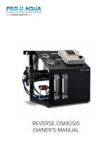
GENERAL SYSTEMS DIAGRAM (WM)
1. Incoming Feed Water
5. Rotary Vane Pump
(Pre-Filter supplied, but not shown)
2. Electrical Control Box 2a:On/Off Switch
2b:Power On Indicator
1
2
2a 2b 2c 2d
3
4
5
6
12
8
9 10 11
7
* This photo is
shown with
options.

Water Tec Int’l. Inc. Version 02A
12
2c:Low Pressure Indicator
2d:5amp Fuse
3. System Pressure Gauge
6. Recycle Needle Valve
7. Solenoid Valve
8. Module – R.O. Membrane & Housing
9. Permeate Flow Meter
10. Concentrate Flow Meter
11. Fiberglass Panel/Frame
12. Pressure Tank (Optional)
4. Motor
GENERAL SYSTEM DIAGRAM (WMXL)
1. Incoming Feed Water
2. Electrical Control Box
2a. On/Off Switch
2b. Power On Indicator
2c. Low Pressure Indicator
2d. 5amp Fuse
2e. OPTION: Digital TDS Meter
3. Control Panel
3a. Permeate Flow Meter
3b. Concentrate Flow Meter
3c. Incoming Pressure Gauge
3d. System Pressure Gauge
3e. Recycle Control Valve
3f. Waste Control Valve
4. Single Cartridge Pre-Filter
2b 2c 2d 2e 2a 3a 3b 3c 3d 3e 3f
3
1
4
2
5
5a
6
7

Water Tec Int’l. Inc. Version 02A
13
5. High Pressure Multistage Pump
5a. Solenoid Valve
6. Module-R.O. Membrane & Housing
7. Powder Coated Steel Frame
GENERAL SYSTEM DIAGRAM (VXL)
1&2. Incoming Feed Water and
Pre-filter (not shown)
3. Electrical Control Box
3a. On/Off Switch
3b. Power On Indicator
3c. Low Pressure Indicator
3d. 5amp Fuse
4. High Pressure Pump and Solenoid
5. Control Panel
5a. Incoming Pressure Gauge
5b. System Pressure Gauge
5c. Waste Control Valve
5d. Recycle Control Valve
5e. Concentrate Flow Meter
5f. Permeate Flow Meter
3
3a 3b 3c 3d
4
5a
5b
5c
5d
5e
5f
6
7

Water Tec Int’l. Inc. Version 02A
14
6. Module-R.O. Membrane Housing
7. Powder Coated Steel Frame
GENERAL SYSTEM DIAGRAM (HXL & HXXL)
1. Incoming Feed Water
2. Single Cartridge Pre-Filter
3. Electrical Control Box
3a. On/Off Switch
3b. Power On Indicator
3c. Low Pressure Indicator
3d. 5amp Fuse
4. Control Panel
4a. Permeate Flow Meter
4b. Concentrate Flow Meter
4c. Incoming Pressure Gauge
4d. System Pressure Gauge
4e. Recycle Control Valve
4f. Waste Control Valve
5. High Pressure Pump and Solenoid
6. Module-
R.O. Membrane & Housing
The HXXL frame has 80” housings
3a 3b 3c 3d
3
4a 4b 4c
4e
4f 4
4d
6
1
2
5
7

Water Tec Int’l. Inc. Version 02A
15
containing two membranes per
housing.
7. Powder Coated Steel Frame
GENERAL SYSTEM DIAGRAM (X)
1. Incoming feed water
2. Pre-Filter 1 and 2
3. Inlet Ball Valve
4. Pump A
5. Pump B (standard equipment has 1 pump)
6. Pump C (cleaning pump) OPTIONAL
7. Control Box
7a. Pump “A” Hour Meter (option)
7b. Pump “B” Hour Meter (option)
7c. Pump “C” Hour Meter (option)
7d. Permeate/Concentrate Flow Meter
7e. Recycle Flow Meter
7f. Power Light
7g. Low Pressure
7h. Over Pressure
7i. Fast Flush
7j. Cleaning (option)
7k. Power Switch
7l. Clean/Auto run Keyed Switch
8. Control Panel
8a. Pre Filter Gauge
8b. Post Filter Gauge
8c. Pump “A” Pressure Gauge
8d. Pump “B” Pressure Gauge
8e. Inter Mediate Membrane Pressure
Gauge
8f. Post Membrane Pressure Gauge
9. Recirculation Valve
10. Concentrate Valve
11. Fast Flush Ball Valve (OPTIONAL)
12. Chemical Tank (OPTIONAL)
13. Module – Membranes and Housing
14. Powder Coated Steel Frame
1
2
3 4 5 6 7
7a
7b 7c
7d 7e
7f 7g 7h 7i 7j
7k 7l
8
8a 8b 8c 8d 8e 8f
9 10 11 12
13
14
* Equipment Pictured Shows Many Options Available

Water Tec Int’l. Inc. Version 02A
REVERSE OSMOSIS SET-UP SPECIFICATIONS
Inlet Water Supply
Inlet Pipe Size Should Never Be Smaller Than Equipment Inlet.
This is the inlet to the pre-filter. Sizing can range from ½” to 3” depending on each piece of equipment. General sizing
is as follows:
CP Series: 150-800GPD – ½”
WMXL / VXL / HXL Series: 1500-4000 GPD – ¾” WMXL / VXL / HXL Series: 4500-10000 GPD – 1”
VXL / HXL Series: 10000-12000 – 1 ½” HXL Series: 12000-18000 GPD – (2) 1 ½”
HXXL Series: 10500-24000 – (2) 1 ½” HXXL Series: 26000-28000 GPD – (3) 1 ½”
X Series: 30000 and larger – 2 –3”
Product Water Outlet
On smaller systems without flow meters, the permeate is always the center outlet of membrane housing end cap. On
most other units the permeate outlet is the outlet of the Product Flow Meter. The location of the permeate outlet on
units 30000 GPD or larger is on the right side of the unit.
Waste Water Outlet
On smaller systems without flow meters, reject outlet is the outside port of membrane housing, on opposite end from
the raw water high-pressure feed. On most other units the concentrate outlet is the outlet of the Waste Flow Meter.
The location of the concentrate outlet on units 30000 GPD or larger is on the right side of the unit.
Electrical Connections and Voltages
All CP and WM Series standard units are 110v/60hz. They have a standard 110v 3 prong plug. WMXL, VXL, and
HXL Series units are available in 110v/60hz or 220v/60hz (single or three phase). Please check your electrical
requirements carefully. The equipment warranty does not cover burnouts or damage to electrical components due to
electrical overcharge or incorrect wiring. The 110v/60hz single-phase units have a standard 110v 3 prong plug. Any
220v/hz or 460v/hz units must be hard wired. HXXL Series units are standard 220v/60hz three-phase. X Series units
are available in 220v/60hz three-phase or 460v/60hz three-phase. All 460v/60hz X Series units also require
110v/60hz circuit to be run to the electrical control box. (All systems must be installed to local codes)
System Control Box:
All Water Tec Commercial / Industrial Reverse Osmosis units use 110v control voltage in the electrical control circuit.
All 220v systems are converted internally to 110v. 460v units require 110v and 460v hard wired circuits.
Liquid Level Control Connections and Switch
Wiring connections for the Liquid Level Switch are located directly on top or on the side of the electrical control box.
The two red wires are connected one to one on the wires from the Liquid Level Switch. When the Liquid Level switch
is closed the R.O. will turn on. When the Liquid Level Switch is open the R.O. will shut down.

Water Tec Int’l. Inc. Version 02A
17
REVERSE OSMOSIS SET-UP, START-UP AND
TESTING PROCEDURES
It is very important to make sure you are aware of all plumbing and electrical codes in your area before you start the
installation or set-up of these systems.
As always, please follow proper plumbing and electrical safety procedures while installing and operating this unit.
Set- Up
q 1. Install the pre-filter (s) into the housing.
q 2. Install the membrane (s) into the housing. The housings will have an arrow showing direction of flow. The
brine seal should always be installed on the same side as the incoming water. See page 18.
q 3. Open the Waste and Recycle Valves until they are fully open.
q 4. Connect all the plumbing. Supply / Permeate / Concentrate. Do not open incoming water supply yet.
q 5. Connect all the electrical connections including the Liquid Level Switch.
Start- Up
q 1. Be sure All pre-treatment is in operation.
q 2. Turn the Power Switch to On. The Power On Indicator and the Low Pressure Indicator will light.
q 3. All the pressure gauges should still read 0.
q 4. Turn on the Incoming Feed Water.
q 5. The Incoming Pressure Gauge should rise above 20 PSI. When the incoming pressure reaches approximately
20 PSI the Low Pressure Indicator will turn off.
q 6. After a delay of 15-30 seconds the pump will turn on. After the pump turns on the System Pressure Gauge will
start to rise. NEVER allow the System Pressure Gauge to exceed 200 PSI unless another
pressure has been indicated directly on the System Control Panel.
q 7. Adjust the Waste Valve by closing it slowly, until the Product and Waste Flow Meters show the same values in
GPM. If the unit is not supplied with flow meters, product and waste flow rates must be checked manually.
NEVER completely close this valve.
q 8. Adjust the Recycle Valve by closing it slowly, until the System Pressure Gauge shows approximately 190-200
PSI. NEVER completely close this valve.
q 9. The reverse osmosis unit is now in operation. Check for leaks. Product water PPM will take about 20 minutes
to reach optimum quality. Provided that pre-treatment is in operation
Initial Testing
After about 30 minutes the incoming and product water should be tested with a TDS Meter. There should be
no less than a 90% rejection. If the rejection is lower than 90% double check the membrane installation and
!
!
!

Water Tec Int’l. Inc. Version 02A
18
the brine seal direction consists of pre-treatment
Initial Testing (continued)
After the quality test you should also test all the electrical equipment. Disconnect the Liquid Level Switch
wires and look for these four things:
The pump should automatically shut down.
There should be continuous flow from the unit to product and waste as the unit drains.
After the short drain out period the flow should completely stop.
The Power On Indicator should remain on.
Reconnect the Liquid Level Switch wires. The pump should automatically turn on. Pressure should increase
and water should start to flow to product and waste.
MEMBRANE INSTALLATION
Ideal Installation
Incorrect Installation
Acceptable Installation
Flow
Flow
Flow
The brine seal should always be
installed on the same side as the
incoming water.
Note the direction of the brine seal.
*
*
*
*

Water Tec Int’l. Inc. Version 02A
19
TROUBLE SHOOTING GUIDE
SYMPTOM POSSIBLE CAUSE SOLUTION
RO unit will not start No electrical power to control circuit Check power supply
On/Off Switch Check power / replace
Time delay not operating Check power / replace
Fuse Check / replace
Coil in magnetic motor starter burned out
Check / replace motor or coil
Liquid Level Control Relay Check for power
Pump motor Check / replace
Low Pressure
Low feed pressure Incoming feed water supply may be off Check
Incoming feed water supply line may be Check / replace line if kinked
Restricted / under sized
Upstream pretreatment Check all pretreatment
Pre-Filter may be clogged / dirty Check / replace
Low Pressure Switch Check for power / replace
No high pressure Reject valve open too far Check / adjust
Reject bypass may be open Check / adjust
High pressure gauge may be broken Check / replace
Restriction in tubing to gauge Check / replace / replace if kinked
Pump impellers may be worn Check / replace impellers or pump
Low water volume to pump Check
No waste water Waste Valve may be closed Check / open / adjust
Clogged drain line Check / replace / replace if kinked
No product water or low Pump pressure may be too low Check / adjust
Product water Waste valve open too far Check / adjust
Membranes may be fouled / dirty Check / clean / replace
Water temperature may be low Check
High TDS in permeate water TDS monitor or probe Check / adjust / replace
Low pump pressure Check / adjust
Membranes may be clogged / dirty Check / clean / replace

Water Tec Int’l. Inc. Version 02A
20
REVERSE OSMOSIS GENERAL PRETREATMENT
These are standard pieces of equipment necessary to help your reverse osmosis operate
correctly. Individual circumstances, configurations and the type of system will determine if all the
above equipment is necessary, if more is necessary or if less can be used.
1. Automatic backwashing sediment filter
This filter should be used in areas with higher sediment content. Dirty water can
clog the pre-filter of the R.O. causing an incoming pressure drop.
2 Automatic backwashing carbon filter
The reverse osmosis unit CANNOT tolerate chlorine. It is very important to properly
maintain the carbon unit. Doing so maintains the life expectancy of your membranes.
3. Twin alternating water softener
Fouling and scaling on the membrane is one of the main reasons a water softener is
recommended before an R.O. It is always best to use a twin alternating unit in order
to ensure continuous soft water.
1 2 3
General Water Plant Set-up
/