Page is loading ...

ENGLISH
Quick Guide
PowerWalker VFI RT HID Series
I. Assembly
The UPS can be assembled in a rack form using rack ears (Rack Mount Kit is not included) or in
tower form using tower holder. The LCD part can be taken out and turned 90 degrees to align
with orientation of the UPS.
Internal batteries are disconnected for transportation. It is necessary to open front panel (2
screws on the side, 1 screw behind the LCD) and connect the two available connectors before
first usage. External batteries are connected in front using third connector.
Details at https://support.powerwalker.com/kb/faq.php?id=83 (faq.powerwalker.com)
II. Display Panel
The LCD uses blue back-light as standard. In case of critical
error the back-light changes to red. Buttons react to:
Click – Press the button for around 1s and
release
Press – Press and hold for more than 3s, release
Press long – Press and hold for more than 10s,
release
Control
Button
Switch
Function
ON /
Alarm
Silence
Press to turn on the UPS.
Click to disable alarm buzzer (press during battery mode).
Press long to perform battery life test
OFF
Press to turn off the UPS. (UPS will switch to bypass if it is configured)
Click to disable alarm buzzer in bypass mode.
Press to release the UPS from fault mode or EPO status.
Select
Press the Select button to select the settings value one by one
Enter
Press to enter settings mode (depending on the UPS Mode)
Click to enter settings item (settings string will flash)
Click to confirm settings
Press to exit Settings mode
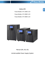
III. Description of LCD display function
No.
Description
Function
Input frequency and
voltage
Indicates the value of input frequency and voltage
Input plug indicator
Lights on when the input power is at no loss.
LCD Screen
ON Button/
Alarm Silence
OFF-Button Select-Button Enter-Button

ENGLISH
Output frequency and
voltage
Indicates the value of output frequency and voltage
Output plug indicator
The UPS has two groups of outlets. The output plug
indicator will light on if there is output power
respectively.
UPS status/user setting
display String
Strings Indicate the UPS status( see Table 4)
Strings Indicate user setting options( see Table 5)
Warning indication
Lights on when the UPS is failure or alarm.
Settings
Lights on when the UPS under settings mode.
Battery volume level
display
Indicates the amount of battery volume remaining.
Each battery volume level bar indicates approximately
20% of total battery volume
Load Power level display
Indicates the load level of the UPS. Each level bar
indicates approximately 20% of the total UPS output
Power.
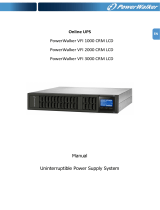
IV. Rear Panels
VFI 1000-1500-2000 RT
VFI 3000 RT
~
~
250V 10A
250V 10A
INTELLIGENT SLOT
RS232
LS2 AC OUTPUT
LS1 AC OUTPUT
~
250V 16A
USB
AC INPUT
DRY IN
EPO
DRY OUT
1
AC Output

ENGLISH
V. Connection of the UPS
The UPS should be protected with circuit breaker on the
input. Minimum rating should 10A for 1000VA, 12A for
1500VA, 16A for 2000VA and 20A for 3000VA. For output
connection please use original cables and share the load
equally among outlets.
VI. Connecting Battery Packs
Remove front panel, connect the battery via Anderson PP45 connectors. Make sure you
are connecting with correct polarity (red to red, black to black). Make sure the wires are
connected tight. Close front panel. Setup the amount of battery packs in the settings.
VII. Communication Ports
A Local communication with the software can be
established via USB or RS232 connector. Alternatively UPS
can be controlled using dry contacts.
VIII. DB9 Female (RS232) pin description
PIN #
Signal name
Function
Direction from the UPS
2
Tx
Transmit to external device
Out
3
Rx
Receive from external device
In
5
GND
Signal common (tied to chassis)
Not applicable
Other
Not Used
Dry contacts are not available for VI ERT series.
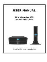
IX. Dry contact port and EPO
The relay output contact must not be connected to any utility connected circuits.
Reinforced insulation to the utility is required. The relay output contact has a maximum
rating of 30Vac/1A.
The signal input to control UPS On/Off status is the same as one button to control UPS
On/Off status. The relay output can be configured by protocol command:
Dry out signal
Description
Summary Alarm
[DEFAULT]
Activated when any warning happens
2
Dry contact input / EPO
3
USB Port
4
AC Input
5
Dry contact output
6
Intelligent Slot
7
RS232
8
Earth Line Port

ENGLISH
On Battery
Activated when the UPS operates on battery
Battery Low
Activated with the “bLOW” alarm
UPS ok
Activated when the UPS has no alarms and no fault.
On Bypass
Activated when the UPS has bypass output.
Dry in signal
Description
UPS On/Off
One second pulse activate, if active, the UPS turns off when UPS is
on inverter; the UPS turns on when UPS is not on inverter. It is the
same as a remote button to control UPS On/Off status.
For more information visit our website.
X. Extension Slot
UPS allows extending communication means by extension cards. Please check product
website for list of accessories.
XI. UPS Initial Startup
1. Verify that the internal batteries (behind front panel) and optional battery packs are
connected.
2. Plug the equipment (load), but do not turn it on
3. Plug in the UPS input power cord. The UPS front panel display illuminates and UPS
status display shows “INIT” for initialization and then settles on “STbY”
4. Press and hold the ON/OFF button more than 3 seconds. The UPS status display
changes to “LINE”
5. Configure the UPS (i.e. EBM battery settings)
At initial startup, the UPS sets system frequency according to input line frequency.
XII. User Setting String
Settings should be done in standby (no output) or bypass mode. Load Segments can be
also changed in Line Mode
LCD String
Description
Values
OPV
Output Voltage
208/220/230/240 (Volt)
OPF
Output Frequency
50/60 (Hz)
bYPA
Bypass Status
Enable (001) / Disable (000)
MOdE
Operating Mode
UPS/ECO/CVF
LS1 / LS2
Load Segments
On (001) / off (000)
EbM
External Battery Modules
0-9
XIII. [UPS] Normal Operating Mode
UPS works in normal double conversion mode, providing clean and filtered power.
XIV. [CVF] Frequency Converter Mode
When input frequency is within 40 Hz to 70 Hz, the UPS can be set at a constant output
frequency, 50 Hz or 60 Hz. The UPS will still charge battery under this mode. Frequency
Converter requires de-rating of the UPS Power to 70%.
XV. [ECO] Economy Mode
It is also referred to as high efficiency mode. The load is supplied directly from mains via
internal filter when input voltage is within the allowed range. If the input is abnormal,
UPS would switch to battery mode. A transfer time up to 10ms is present during switching
to battery mode.
XVI. Configuring EBM quantity

ENGLISH
Setting correct EBM (External Battery Module) quantity is critical for reaching the desired
backup time. Only if this value is set correctly, UPS will be able to maximize the battery
usage. The value represents amount of original battery packs fitted with 2 strings of 9Ah
batteries.
XVII. Configuring Load Segment
Load segments are groups of outlets that can be configured through the display. VFI RT
HID models have two configurable load segments. When UPS is turned on (it has
activated output), you can turn off a load segment. If the UPS is turned off (no output),
then a load segment cannot be turned on.
XVIII. Bypass Mode
If the bypass is set to enabled (value = 001), then the UPS would provide output to the
load as long as there is input. Turning off the UPS would essentially switch off the inverter
and supply unfiltered power to the load.
XIX. UPS Status Display String
LCD Display String
Description
STbY
UPS work at Standby mode (no output)
LINE
UPS work in Line mode
bYPA
UPS work in Bypass mode (no backup function!)
bATT
UPS work in Battery mode (no AC input)
TEST
UPS work in battery life/function test mode
ECO
UPS work in ECO mode
CVCF
UPS work in converter mode
SITE
Site fail, check input connection
FANF
Fan fail, check if fan is not blocked
bLOW
Battery low, recharge or replace batteries
bOPN
Battery open, check battery circuit connection
bATF
Battery fault, replace batteries
EPO
EPO, deactivate EPO
OVLD
Overload, disconnect load
AMbH
Ambient temperature too high
For following errors contact our technical support: CHGF / TEPH / SHOR / ISFT / bSFT / OVTP /
INVL / INVH / bUSH / bUSL / bUSE / bUSS / HIGH / NTCO
XX. Indicators and Audible alarm
Audible alarm
Backup Mode
Sounding every 4seconds
“bATT” on the screen
Low Battery
Sounding every second
“bLOW” on the screen
UPS Fault
Continuously Sounding
Red display
Overload
Sounding every second
“OVLD” on the screen
Battery Replacement
Sounding every second
Alarm can be muted when it is activated, but it will sound in case of low battery, fan
fault, overheat and other major fault.
XXI. Technical Specification

ENGLISH
Model
1000 RTS
1000 RT
1500 RT
2000 RT
3000 RT
Power
Watt
900W
900W
1350W
1800W
2700W
Input
Input voltage range
161-276VAC
Frequency range
45-55 or 54-66 Hz for Normal Mode
Output
Voltage
220/230/240VAC
Voltage Regulation
±5% in battery mode
Frequency
50Hz or 60Hz ±0.2Hz
Waveform
Pure sinewave
Overload rating
12s @102%-130%; 1.5s @130%-150%; 100ms @ >150%
Internal
battery
Battery Type
external
3x12V/7A
H
4x12V/7A
H
4x12V/9
AH
6x12V/9A
H
Recharge Time to
90% after
discharged
N/A
3 hours
Temperature
0 to 40°C
Humidity
0%-95% relative humidity (non-condensing)
Altitude
<1000m
Storage Temperature
0-45 degC
Net weight
8.4kg
16.2kg
19.7kg
19.7kg
28.6kg
Dimensions
438 x 86.5 x 436
438X87x6
08
/