
Read this manual before using product. Failure to
follow instructions and safety precautions can
result in serious injury, death, or property
damage. Keep manual for future reference.
Part Number: RNF-3066 R2
Revised: March 2017
Retro Rocket
Aeration System
Installation Manual
This manual applies to:
GRS–7004 / GRS-7006
Original Instructions


Contents 3
CONTENTS
1. Introduction
2. Safety
2.1. Safety Alert Symbol and Signal Words..................................................................................... 5
2.2. General Safety .......................................................................................................................... 5
2.3. Personal Protective Equipment................................................................................................ 5
2.4. Safety Equipment ..................................................................................................................... 6
3. Installation
3.1. Installation Safety..................................................................................................................... 7
3.2. Check Shipment........................................................................................................................ 7
3.3. Required Tools.......................................................................................................................... 7
3.4. Location Requirements ............................................................................................................ 7
3.5. Methods of Installation............................................................................................................ 8
3.5.1 Hopper Bins with Small Access Opening ................................................................... 8
3.5.2 Hopper Bins with Large Access Opening ................................................................. 10
3.6. Attach the Weatherstripping on the Panels .......................................................................... 11
3.7. Unfold the Retro Rocket ........................................................................................................ 13
3.8. Attach the Retro Rocket......................................................................................................... 15
3.9. Attach the Air Inlet................................................................................................................. 15
3.10. Attach the Duct Elbow ......................................................................................................... 16
4. Specifications ........................................................................................................................................ 18
5. Appendix ............................................................................................................................................... 19
6. Warranty ............................................................................................................................................... 21

4
1. Introduction
Before assembling the rocket, please read this manual. Familiarize yourself with the process and the
necessary precautions for efficient and safe assembly.
Everyone present at the assembly site is required to be familiar with all safety precautions.
Keep this manual available for frequent reference and review it with new personnel. Call your local
distributor or dealer if you need assistance or additional information.
General Description
The Grain Guard Retro Rocket is an excellent addition to any new or existing hopper bottom bin that
does not presently include an aeration system. It can allow you to harvest in damp conditions,
maintain stored grain in peak condition, and reduce the likelihood of mould growth and insect
infestations.
Key features of Grain Guard Retro Rocket:
• Fits through existing bin openings that are at least 19” square, 22” diameter, or 18.5” x 16” oval
openings
• Reduces grain drying time and increase fan efficiency by directing air into the core of the bin.
• Unique folding design allows it to be installed through an opening much smaller than itself.
• Inserts through smaller openings that are at least 16” round or 12” square by removing four bolts
and inserting the rocket in sections.
• Can be assembled and unfolded into working position once inside the bin.
With proper care during and after installation, your aeration system will provide you with many years
of trouble-free service.
Intended Use
The rocket is designed solely for use in customary agricultural or similar operations. Use in any other
way is considered as contrary to the intended use. Compliance with and strict adherence to the
conditions of operation and maintenance as specified by Grain Guard, also constitute essential
elements of the intended use.
Any modifications carried out to the rocket may relieve Grain Guard of liability for any resulting
damage or injury.
The Retro Rocket may be safely used with grains of all types, do not use with fertilizer.
1. INTRODUCTION RETRO ROCKET

5
2. Safety
2.1. Safety Alert Symbol and Signal Words
This safety alert symbol indicates important safety messages in this manual. When you see
this symbol, be alert to the possibility of injury or death, carefully read the message that
follows, and inform others.
Signal Words: Note the use of the signal words DANGER,WARNING,CAUTION, and NOTICE with the safety
messages. The appropriate signal word for each message has been selected using the definitions below as a
guideline.
Indicates an imminently hazardous situation that, if not avoided, will result in serious injury or
death.
Indicates a hazardous situation that, if not avoided, could result in serious injury or death.
Indicates a hazardous situation that, if not avoided, may result in minor or moderate injury.
Indicates a potentially hazardous situation that, if not avoided, may result in property damage.
2.2. General Safety
The safety information in the safety section of this manual applies to all safety practices. Specific safety
information (such as Assembly Safety), can be found in the appropriate section.
YOU are responsible for the SAFE assembly and installation of your rocket. YOU must ensure that you and
anyone else who is going to work around the rocket understands all procedures and related SAFETY information
contained in this manual.
Remember, YOU are the key to safety. Good safety practices not only protect you, but also the people around
you. Make these practices a working part of your safety program. All accidents can be avoided.
• It is the rocket assembler and installation personnel’s responsibility to read and
understand ALL safety instructions, safety decals, and manuals and follow them
when assembling, operating, or maintaining the equipment.
• Only experienced personnel who are familiar with this type of assembly and installation should perform this
work. Untrained assemblers/installers expose themselves and bystanders to possible serious injury or death.
• Do not modify the rocket in any way without written permission from the manufacturer. Unauthorized
modification may impair the function and/or safety, and could affect the life of the rocket. Any unauthorized
modification of the rocket will void the warranty.
2.3. Personal Protective Equipment
The following Personal Protective Equipment (PPE) should be worn at all times when assembling the equipment.
RETRO ROCKET 2. SAFETY

6
Work Gloves
• Wear work gloves to protect your hands from sharp and rough edges.
Safety Glasses
• Wear safety glasses at all times to protect eyes from debris.
Steel-Toe Boots
• Wear steel-toe boots to protect feet from falling debris.
Hard Hat
• Wear a hard hat to help protect your head.
2.4. Safety Equipment
The following Safety Equipment should be kept on site:
Fire Extinguisher
• Provide a fire extinguisher for use in case of an accident. Store in a highly visible and
accessible place.
First-Aid Kit
• Have a properly-stocked first-aid kit available for use should the need arise, and
know how to use it.
2. SAFETY RETRO ROCKET

7
3. Installation
Before continuing, ensure you have completely read and understood this manual’s
Safety section, in addition to the safety information in the section(s) below.
3.1. Installation Safety
• Do not take chances with safety. The components can be large, heavy, and hard to handle.
Always use the proper tools, rated lifting equipment, and lifting points for the job.
• Always have two or more people installing the rocket.
• Make sure you have sufficient lighting for the work area.
• Tighten all fasteners according to their specifications. Do not replace or substitute bolts,
nuts, or other hardware that is of lesser quality than the hardware supplied by the
manufacturer.
3.2. Check Shipment
Inspect the rocket and accessories on receipt to ensure that all items have arrived and that none are damaged.
A packing list is included in every crate for reference.
Report missing or damaged parts immediately to ensure that proper credit is received from Grain Guard or your
distributor/dealer, and to ensure that any missing parts can be shipped quickly to avoid holding up the
installation.
Important
Do not use damaged components.
3.3. Required Tools
• SAE wrench and rachet set (3/8”, 7/16”, 1/2”, 9/16”,
1–1/8”)
• Level
• Electric drill with drill bits (3/16”, 7/16”, 13/32”) • Tin snips
• Marker • Silicone
• Torch or grinder with cutting wheel • Winching device with minimum load rating of 700
lbs
• Impact driver or drill with 3/8” driver bit
3.4. Location Requirements
All models of the Grain Guard Retro Rocket are designed to be installed in the center of hopper-bottom bins
with the rocket center aligned with the center of hopper cone. To ensure structural integrity and proper airflow,
the bin must be level and the rocket installed completely vertical.
RETRO ROCKET 3. INSTALLATION

8
Grain Guard Retro Rocket are not to be used on hopper slopes more than 40° from the
horizontal. For hoppers with slopes steeper than 40°, consult Grain Guard before installation.
3.5. Methods of Installation
The two installation methods are covered in the following sections. The correct method to use depends on the
opening size of the bin. Review both methods and confirm which will work best for your application. Also note
that with the right lifting equipment, the Retro Rocket could also be inserted into the bin through the filler cap
or inspection hatch.
To prevent equipment damage:
• Check the bin manual to ensure bin roof is capable of holding at least 700 lbs concentrated
load from the filler cap.
• If the bin roof is not capable of holding at least 700 lbs, use lifting apparatus rated to
withstand the intended load.
3.5.1 Hopper Bins with Small Access Opening
Required minimum opening:
• Square: 16” to 18.5”
• Round: 16” to 22”
1. Lay the rocket with the louvered side facing down.
2. Remove the banding around the rocket.
3. Remove the bolts from the hinges located between the 2nd and 3rd panels.
4. Remove the bolts from the hinges located between the 4th and 5th panels.
5. Winch the panels 1 and 2 off together and place inside the bin through the bin opening.
6. Lay the panels on the hopper cone with the side with hinge facing upward and leg pointing downward.
7. Winch the panels 3 and 4 off together and place inside the bin through the bin opening.
8. Align the hinge holes of panels 2 and 3 and place the hinge bolts back in place.
9. Winch the panels 5 and 6 off together and place inside the bin through the bin opening.
10. Align the hinge holes of panels 4 and 5 and replace the hinge bolts.
3. INSTALLATION RETRO ROCKET


10
3.5.2 Hopper Bins with Large Access Opening
Required minimum opening:
• Square: 18.5”
• Round: 22”
• Oval or rectangle: 16” x 19”
1. Attach a lifting cable onto the lugs located on the 2nd and 5th panels.
2. Position the folded up rocket into the opening of the hopper cone.
3. Winch and guide the rocket through the bin opening.
4. Remove the banding around the rocket.
Figure 3. Panels through the Bin Opening
3. INSTALLATION RETRO ROCKET

11
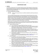
Figure 4. Lifting Panels inside the Bin
To prevent personal injury or damage to equipment:
• Do not drop the panels
• Use a winching device with minimum load rating of 700lbs
3.6. Attach the Weatherstripping on the Panels
Note
Weatherstripping can be applied prior to lifting rocket into the bin. If this is done, care must be taken
not to damage weatherstripping during the lifting process. Visual inspection of the weatherstripping is
advised after the rocket is in the bin.
1. Cut the provided weatherstripping to length.
2. Attach the weatherstripping as shown in the following figures.
RETRO ROCKET 3. INSTALLATION


13
3.7. Unfold the Retro Rocket
Below is a suggested sequence to unfold the rocket.
Pinching Hazard
• Hold swinging sections firmly prevent loss of grip and panels closing together too quickly.
• Do not place fingers in between panels that hinge together.
1. If not still attached, connect a lifting cable onto the lugs located on the 2nd and 5th panels.
Note
Sections can be fastened together with a clamp, wire or other means to prevent panels from
swinging outward during lifting.
2. Winch the rocket with a lifting device until it is 30” to 36” off the bottom of the hopper cone.
Figure 7. Suspended Panels inside the Bin
Note
For Step 3 on page 13 to Step 13 on page 14:
• use punch to help align holes when needed
• install hardware hand tight only to allow adjustment
3. Swing the panels 1 and 2 together until the edge surfaces of panels 2 and 3 are in contact. See Figure 8.
4. Insert a 5/16” x 1” bolt through the top flanges (A) of panels 2 and 3.
RETRO ROCKET 3. INSTALLATION

14
5. Swing the panels 5 and 6 together until the edge surfaces of panels 4 and 5 are in contact.
6. Insert a 5/16” x 1” bolt through the top flanges (B) of panels 4 and 5.
7. Unfold panel 1 until its edge is resting on panel 2.
8. Insert a 5/16” x 1” bolt through the top flanges (C) of panels 1 and 2.
9. Unfold panel 6 until its edge is resting on panel 5.
10. Insert a 5/16” x 1” bolt through the top flanges (D) of panels 5 and 6.
11. Connect the top flanges between panels 3 and 4 and panels 1 and 6.
12. Connect all the remaining top flanges using 5/16” x 1” bolts.
13. Fasten all 3/8” x 1” bolts through leg halves.
14. Tighten all top flange and leg bolts.
Figure 8. Unfolding the Panels
3. INSTALLATION RETRO ROCKET

15
3.8. Attach the Retro Rocket
1. Orient the inlet opening towards the desired fan location.
2. Lower the rocket assembly while ensuring that it is centered over the discharge at the bottom cone and
aligned vertically.
Note
Vertical alignment is critical to structural integrity of the rocket. Use level or plumb bob on all sides
to check alignment.
3. Mark the bolt holes of the rocket feet on the hopper.
4. Lift the rocket up and drill hole the locations with a 13/32” drill bit.
5. Lower the rocket down onto the hopper and loosely install 3/8” x 1–1/4” bolts at the two feet opposite the
inlet.
Note
Leave the bolts for the foot closest to the inlet opening until the straight duct is attached.
3.9. Attach the Air Inlet
1. Insert the top flange of the air inlet under the louvered sheet while the side flanges are resting along the
sides of the rocket inlet opening.
2. Loosely install 1/4” x 3/4” bolts on both sides and bottom of the air inlet.
3. Fasten the air inlet at top using four #14 x 3/4” tek screws.
4. Tighten bolts at the sides and bottom of the air inlet.
5. Insert the straight duct to the air inlet.
Note
With the winch cable still attached and 1–2’ of slack in the cable, tip the rocket back until the
straight duct can be slid into the air inlet opening. Once the straight duct is in place, lower the
rocket back to a vertical position.
Pinching hazard
When lowering rocket, keep hands and body clear of air inlet and rocket foot.
6. Mark the outer edge of the straight duct on the hopper cone.
7. Remove the straight duct by tipping the rocket back again.
8. Check the size of the inlet opening outline before cutting. The hole should not be less than 8–7/8” x 13–7/8”
and not more than 9” x 14”.
9. Cut the inlet opening using torch or cutting wheel.
Note
Cut inside the marked line to keep the opening as clean as possible.
Grain Dust Explosion Hazard
When cutting air inlet opening, keep work area free of dust and debris.
10. Reinstall the straight duct into the air inlet. The straight duct should now fit through the cut hole. If not,
enlarge hole as required.
RETRO ROCKET 3. INSTALLATION

16
11. Ensure the straight duct is aligned with the cut hole.
12. Attach the straight duct to the air inlet using twelve #14 x 1” sheet metal screws (four on sides, two on top
and bottom).
13. Trim off any protruding portion of the straight duct outside the exterior hopper wall.
14. Loosely fasten the last bolt in the rocket foot by the inlet.
15. Check the vertical alignment of the rocket, adjust as required.
16. Tighten the bolts on the rocket’s feet.
3.10. Attach the Duct Elbow
1. Place the angle iron frame over the elbow on the uncapped (short) side of the elbow with the flat side of
frame facing the opening.
2. Insert the duct elbow through the cut hole and into the straight duct until there is an overlap of at least
1–1/2”. Hold the elbow at this position.
Note
Ensure straight duct and duct elbow (short end) are aligned and the long end of the elbow is parallel
to the ground.
3. Move the elbow angle frame up until it is flush with the hopper cone.
4. Mark the locations of the bolt holes:
• 12 holes through the elbow angle frame and hopper cone
• 8 holes though the elbow angle frame and duct elbow
5. Remove the duct elbow and angle frame.
6. Pre-drill the marked holes with 3/16” drill bit and drill out using a 7/16” drill bit.
7. Attach the elbow angle frame to the duct elbow using eight 3/8” x 1–1/4” bolts and 3/8” nuts.
8. Insert the assembled duct elbow and elbow angle frame into the hopper cone opening.
9. Secure the elbow angle frame to the hopper cone using twelve 3/8” x 1–1/4” bolts and 3/8” nuts.
10. Attach the duct elbow to the straight duct using twelve #14 x 1” sheet metal screws. Use four screws on
each side and two screws on the top and bottom of the duct.
3. INSTALLATION RETRO ROCKET


19
5. Appendix
5.1. Aeration System Parts List
GRS-7004
Item Part Number Description Quantity
1Call for Parts 4’ Rocket body 1
2 RZF-7294 9” x 14” Inlet 1
3 RZA-7232 15–1/8” Rectangular Duct 1
4 RGA-5032 9” x 14” Elbow Angle Frame 1
5 RZA-7230 9” x 14” Elbow Assembly (includes Weather Cap) 1
6 GGA-8618 9” x 14” Weather Cap 1
7 RBF-2362 Foot, Retro Rocket 3
8 RNF-7295 Hardware Bag, Retro Rocket 1
RETRO ROCKET 5. APPENDIX

20
GRS-7006
Item Part Number Description Quantity
1Call for Parts 6’ Rocket body 1
2 RZF-7294 9” x 14” Inlet 1
3 RZA-7232 15–1/8” Rectangular Duct 1
4 RGA-5032 9” x 14” Elbow Angle Frame 1
5 RZA-7230 9” x 14” Elbow Assembly (includes Weather Cap) 1
6 GGA-8618 9” x 14” Weather Cap 1
7 RBF-2362 Foot, Retro Rocket 3
8 RNF-7295 Hardware Bag, Retro Rocket 1
5. APPENDIX RETRO ROCKET
Page is loading ...
Page is loading ...
-
 1
1
-
 2
2
-
 3
3
-
 4
4
-
 5
5
-
 6
6
-
 7
7
-
 8
8
-
 9
9
-
 10
10
-
 11
11
-
 12
12
-
 13
13
-
 14
14
-
 15
15
-
 16
16
-
 17
17
-
 18
18
-
 19
19
-
 20
20
-
 21
21
-
 22
22


AGI RNF-3066 R2 - GG Retro Rocket 7004 7006 Owner's manual
- Type
- Owner's manual
- This manual is also suitable for
Ask a question and I''ll find the answer in the document
Finding information in a document is now easier with AI
Related papers
Other documents
-
 Cirrus SR20 Maintenance Manual
-
Seagull SEA232 User manual
-
-
Apogee 05061 Black Brant VC User manual
-
 Drolet ROCKET WOOD STOVE Owner's manual
-
aero-naut Dassault Breguet Rafale C 01 Building Instructions
-
Phoenix R/C Aerobatic Glider Assembly And Operation Manual
-
Razor Dirt Rocket MX350 Owner's manual
-
Razor MX650 User manual
-
Razor MX650 User manual

