Page is loading ...

Part Number: RNA-2864 R4
Revised: 2/8/18
Read this manual before using product. Failure
to follow instructions and safety precautions can
result in serious injury, death, or property
damage. Keep manual for future reference.
GRAIN GUARD ROCKET
6000/7000/8000/CR 8000 SERIES
INSTALLATION MANUAL

This product has been designed and constructed according to general engineering
standardsa. Other local regulations may apply and must be followed by the operator.
We strongly recommend that all personnel associated with this equipment be trained
in the correct operational and safety procedures required for this product. Periodic
reviews of this manual with all employees should be standard practice. For your
convenience, we include this sign-off sheet so you can record your periodic reviews.
a. Standards include organizations such as the American Society of Agricultural and Biological Engineers,
American National Standards Institute, Canadian Standards Association, International Organization for
Standardization, EN Standards, and/or others.
Date Employee Signature Employer Signature

TABLE OF CONTENTS
EDWARDS - GRAIN GUARD ROCKET
6000/7000/8000/CR 8000 SERIES
RNA-2864 R3 3
1. Introduction.......................................................................................................................... 5
2. Safety First............................................................................................................................ 7
2.1. General Safety ......................................................................................................... 7
3. Installation ............................................................................................................................ 9
3.1. Location.................................................................................................................... 9
3.2. Installation................................................................................................................ 9
4. Appendix............................................................................................................................. 17
Warranty.................................................................................................................................. 21

EDWARDS - GRAIN GUARD ROCKET
6000/7000/8000/CR 8000 SERIES
4RNA-2864 R3

EDWARDS - GRAIN GUARD ROCKET 1. INTRODUCTION
6000/7000/8000/CR 8000 SERIES
RNA-2864 R3 5
1.Introduction
Thank you for your purchase.
The Grain Guard Rocket
6000/7000/8000/CR 8000 is
an excellent addition to any
bin and it will allow you to
harvest in damp conditions,
maintain stored grain in peak
condition, and prevent mold
growth and insect infestation.
With proper care during and
after installation, your aeration
system will provide you with
many years of trouble-free
service.
The Grain Guard Rocket is
designed to reduce grain
drying time and increase fan
efficiency by forcing air into
the center of the bin. This
system dries grain more
uniformly and efficiently than
conventional bottom-up
aeration systems.
Safe, efficient and trouble-free
operation of the Rocket
aeration system requires that
you, and anyone else who
may operate this equipment,
read and understand all safety
instructions and procedures.
Keep this manual handy for
frequent reference and to review with new personnel. Call your local distributor or
dealer if you need assistance or additional information.
Note: The Grain Guard Rocket is intended for grain use only. Do not use with fertilizer
or other material.

1. INTRODUCTION EDWARDS - GRAIN GUARD ROCKET
6000/7000/8000/CR 8000 SERIES
6RNA-2864 R3

EDWARDS - GRAIN GUARD ROCKET 2. SAFETY FIRST
6000/7000/8000/CR 8000 SERIES 2.1. GENERAL SAFETY
RNA-2864 R3 7
2.Safety First
2.1. GENERAL SAFETY
• It is the equipment owner and the operator's responsibility to read and under-
stand ALL safety instructions, safety decals, and manuals and follow them
before assembling operating, or maintaining the equipment. All accidents can
be avoided.
• Use this equipment for its intended purposes only.
• Do not modify the equipment in any way. Unauthorized modification may
impair the function and/or safety, and could affect the life of the equipment.
Any modification to the equipment voids the warranty.
• Have a first-aid kit available for use should the need arise, and know how to
use it.
• Wear appropriate protective gear. This list includes, but
is not limited to:
• a hard hat
•gloves
• protective shoes with slip-resistant soles
• protective goggles
• hearing protection
• Follow good shop practices:
• keep service area clean and dry
• be sure electrical outlets and tools are properly grounded
• use adequate light for the job at hand
• Think SAFETY! Work SAFELY!

2. SAFETY FIRST EDWARDS - GRAIN GUARD ROCKET
2.1. GENERAL SAFETY 6000/7000/8000/CR 8000 SERIES
8RNA-2864 R3

EDWARDS - GRAIN GUARD ROCKET 3. INSTALLATION
6000/7000/8000/CR 8000 SERIES 3.1. LOCATION
RNA-2864 R3 9
3.Installation
The following location and installation instructions apply to the 6000, 7000, and
8000 Series Rockets. The specifications for these aeration systems are given in
the table below.
RNA-2864 R3
3.1. LOCATION
All models of the Grain Guard Rocket are designed to be installed in the center of
hopper-bottom bins, with the rocket center aligned with the center of hopper
cone. To ensure proper airflow, the rocket must be installed completely vertical.
3.2. INSTALLATION
Refer to Figure 3.5, one of Figures 4.1–4.4, and one of Tables 4.1–4.4 found in
Appendix during installation, depending on the model being installed.
The following tools are required for proper installation:
• 9/16” wrench
• electric drill with 7/16” bit
• marker
• torch or cutting wheel
• level
•tin snips
• safety equipment (e.g. goggles)
• silicone
Series Part No. Maximum
Sidewall
Height
Rocket Diameter
(outer/inner) Bin Size Airflow Cap-
acity (CFM)
@ 1 cfm/bus
Air Inlet
Size
GG 6000 6’ GGR-8736 15’ 15” slim rocket (for
existing bins) 1200 to 2500 bu. 3,000 9” x 14”
GG 7000 4’ GGR-8737 30’ 30”/20” 1500 to 3500 bu. 6,000 9” x 14”
GG 7000 6’ GGR-8738 30’ 30”/20” up to 5000 bu. 7,000 9” x 14”
GG 7000 8’ GGR-8739 30’ 30”/20” up to 6000 bu. 9,000 9” x 14”
GG 8000 4’ GGR-8740 30’ 45”/30” up to 7000 bu. 9,000 12” x 17”
GG 8000 6’ GGR-8741 30’ 45”/30” up to 8000 bu. 11,000 12” x 17”
GG 8000 8’ GGR-8742 30’ 45”/30” up to 10000 bu. 13,500 12” x 17”
CR 8000 4’ GGR-8743 40’ 45”/30” up to 15000 bu. 9,000 12” x 17”
CR 8000 6’ GGR-8744 40’ 45”/30” up to 20000 bu. 11,000 12” x 17”
CR 8000 8’ GGR-8745 40’ 45”/30” up to 25000 bu. 13,500 12” x 17”
NOTICE
Grain Guard Rockets are not to be used on hopper slopes
more than 40° from the horizontal. For hoppers with slopes
steeper than 40°, consult Edwards before installation.

3. INSTALLATION EDWARDS - GRAIN GUARD ROCKET
3.2. INSTALLATION 6000/7000/8000/CR 8000 SERIES
10 RNA-2864 R3
For GG 6000 6’ only (on existing bins):
1. Unbolt and remove air inlet on rocket if required to fit through existing
manhole.
2. Do likewise with legs if required.
3. Once inside, replace legs, assemble in the installed position as shown in
Figure 4.1.
4. Replace air inlet and apply silicone around inlet. Bolt back in place.
For all Grain Guard Rockets:
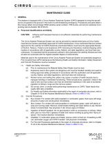
1. Attach feet to legs with 3/4 x 4” bolts and 3/4” locknuts as shown in
Figure 3.2.
2. Unfold legs by removing the three 3/16 x 4” bolts and lowering legs to
assembled position as shown in Figure 3.1.
3. Place 3/4” x 4” bolt through top lug on vertical leg and top of diagonal leg
brace. Repeat for all legs. Tighten all 3/4” bolts (three per leg).
4. Secure 17” straight duct to air inlet with eleven #14 x 3/4” tek screws on 6000/
7000 rockets or fourteen #14 x 3/4” tek screws on 8000 rockets as shown in
Figure 3.3.
5. Center rocket in bin over hopper unload chute. Use a level to ensure rocket
sits true to both the horizontal and the vertical.

EDWARDS - GRAIN GUARD ROCKET 3. INSTALLATION
6000/7000/8000/CR 8000 SERIES 3.2. INSTALLATION
RNA-2864 R3 11
Figure 3.1
3/4” X 4” BOLT
3/4” LOCKNUT
3/16” X 4” BOLT
3/16” LOCKNUT
AIR INLET
VERTICAL LEG
DIAGONAL LEG

3. INSTALLATION EDWARDS - GRAIN GUARD ROCKET
3.2. INSTALLATION 6000/7000/8000/CR 8000 SERIES
12 RNA-2864 R3
Figure 3.2
6. Mark outline of outside of straight duct on hopper cone for inlet opening as
shown in Figure 3.3.
7. Rotate rocket in bin so it is out of the way and cut inlet opening in hopper
cone. A torch or cutting wheel is recommended.
Important: Make cut inside the marked line to help keep the opening as clean as possible.
Ensure that the minimum size of hole is 8-7/8” x 13-7/8”, and that the maximum
size is no larger than 9” x 14”. This means dimension A in Figure 3.3 will be
between 8-7/8” and 9” long and dimension B in Figure 3.3 will be between
13-7/8” and 14” long.
CAUTION
Wear protective eyewear while cutting
opening in hopper cone.
3/4” LOCKNUT
LEG
3/4” X 4” BOLT
ROCKET -
ASSEMBLED
POSITION
FOOT

EDWARDS - GRAIN GUARD ROCKET 3. INSTALLATION
6000/7000/8000/CR 8000 SERIES 3.2. INSTALLATION
RNA-2864 R3 13
Figure 3.3 (7000 Model Shown)
17” STRAIGHT DUCT
AIR INLET
8000 - #14 X 3/4” TEK
SCREWS (QTY. 14)
6000/7000 - #14 X 3/4”
TEK SCREWS (QTY. 11)
MARK OUT HERE
FOR OPENING.
CUT OUT OPENING
USING TORCH OR
CUTTING WHEEL, AS
PER INSTRUCTIONS
ON PRECEDING PAGE.
A
B

3. INSTALLATION EDWARDS - GRAIN GUARD ROCKET
3.2. INSTALLATION 6000/7000/8000/CR 8000 SERIES
14 RNA-2864 R3
8. Re-align rocket in bin so that the 17” straight duct lines up with the
rectangular inlet opening on the hopper. With the rocket in a vertical position,
check if any of the straight duct protrudes outside the exterior hopper wall
(this may occur on hopper cones that have fewer degrees of slope).
• Trim off any excess straight duct with tin snips to make duct flush with
hopper cone.
9. Install duct elbow as follows (see Figure 3.4):
a. Place elbow angle frame on the uncapped (short) end of duct elbow.
Ensure that the flat side of elbow angle frame faces outward on duct elbow.
b. Insert duct elbow and elbow angle frame into the precut opening and the
17” straight duct until at least 1-1/2” of the elbow is inside the hopper cone
and straight duct. Ensure that the long edge of elbow is parallel to the
ground. Support elbow in this position.
c. Move elbow angle frame up duct elbow until it lays flush against the hopper
cone. Mark the location of all holes:
• 16 holes on 8000, 12 holes on 6000/7000 through elbow angle frame and
hopper cone.
• 16 holes on 8000, 12 holes on 6000/7000 through elbow angle frame and
duct elbow.
d. Remove duct elbow and elbow angle frame from inlet hole and pre-drill all
marked holes with a 3/16” drill bit, then drill out with a 7/16” drill bit.
e. Slide duct elbow and elbow angle frame back into opening and straight
duct. Ensure that the long edge of elbow is parallel to the ground.
f. Fasten elbow angle frame to hopper cone (16 places on 8000, 12 places
on 6000/7000) and to elbow (16 places on 8000, 12 places on 6000/7000)
with 3/8” x 1-1/4” bolts, flatwashers/lockwashers and nuts, as shown in
Figure 3.4.

EDWARDS - GRAIN GUARD ROCKET 3. INSTALLATION
6000/7000/8000/CR 8000 SERIES 3.2. INSTALLATION
RNA-2864 R3 15
Figure 3.4 (7000 Model Shown)
DUCT ELBOW
ELBOW ANGLE FRAME
#14 X 3/4” TEK SCREW
3/8” X 1-1/4” BOLTS, FLAT WASHERS
AND LOCKNUTS
3/8” X1-1/4” BOLTS

3. INSTALLATION EDWARDS - GRAIN GUARD ROCKET
3.2. INSTALLATION 6000/7000/8000/CR 8000 SERIES
16 RNA-2864 R3
10. Ensure that 17” straight duct is aligned over duct elbow. Fasten 17” straight
duct to duct elbow using twelve #14 x 3/4” tek screws on 6000/7000 rockets
or sixteen #14 x 3/4” tek screws on 8000 rockets as shown in Figure 3.4. Use
4 screws on each side and 2 screws on both the top and the bottom of the
duct.
11. Using the holes in rocket feet as a guide, drill 7/16” holes in the hopper cone
as shown in Figure 3.5. Attach rocket feet to hopper cone with 3/8” x 1-1/4”
bolts, flatwashers and nuts. See Figure 3.5.
Figure 3.5
DRILL 7/16” HOLES
THROUGH BIN
SHEET
3/8” X 1-1/4” BOLT,
FLATWASHERS (X2)/
LOCKWASHER, AND
LOCKNUT

EDWARDS - GRAIN GUARD ROCKET 4. APPENDIX
6000/7000/8000/CR 8000 SERIES
RNA-2864 R3 17
4.Appendix
Figure 4.1 GG 6000 Series Rocket
Table 4.1 GG 6000 Series Components
ITEM NO. PART NO. DESCRIPTION QTY.
1 – GG6000 Rocket Body Diameter 6’ 1
2RVA-5027 GG6000 Inlet (9” X 14”) 1
3RZA-7230 9” X 14” Elbow w/ Weather Cap 1
4RGA-5032 9” X 14” Elbow Angle Frame (Curved) 1
5RZA-7228 Rectangular Duct Section (17”) 1
6RBF-2362 Rocket Foot 3
7RBA-4031 Rocket Leg, Lower 3
8RBA-4033 Rocket Leg, Upper 3
9RBA-4035 Rocket Channel 3
;
%2/76
;
7(&.6&5(:6
;
7(&.6&5(:6
;
%2/76
;
%2/76
;%2/7
$1'/2&.187
;%2/7
$1'/2&.187
;%2/7
$1'/2&.187

4. APPENDIX EDWARDS - GRAIN GUARD ROCKET
6000/7000/8000/CR 8000 SERIES
18 RNA-2864 R3
Figure 4.2 GG 7000 Series Rocket
Table 4.2 GG 7000 Series Components
ITEM NO. PART NO. DESCRIPTION QTY.
1 – GG7000 Rocket Body 30” Diameter (4’, 6’, or 8’) 1
2RUB-5035 GG7000 Inlet (9” X 14”) 1
3RZA-7230 9” X 14” Elbow w/ Weather Cap 1
4RGA-5032 9” X 14” Elbow Angle Frame (Curved) 1
5RZA-7228 Rectangular Duct Section (17”) 1
6RBA-1240 Rocket Foot 3
7RBB-2857 Rocket Leg Lower 3
8RBB-2858 Rocket Leg Upper 3
9RBB-2859 Rocket Channel 4’ 3
10 RBB-2860 Rocket Channel 6’ 3
11 RBB-2861 Rocket Channel 8’ 3

EDWARDS - GRAIN GUARD ROCKET 4. APPENDIX
6000/7000/8000/CR 8000 SERIES
RNA-2864 R3 19
Figure 4.3 GG 8000 Series Rocket
Table 4.3 GG 8000 Series Components
ITEM NO. PART NO. DESCRIPTION QTY
1 – GG8000 Rocket Body 45” Diameter (4’, 6’, or 8’) 1
2RZC-7314 GG8000 Inlet (12” X 17”) 1
3RZC-7308 12” X 17” Elbow w/ Weather Cap 1
4RGC-5242 12” X 17” Elbow Angle Frame (Curved) 1
5RZC-7307 Rectangular Duct Section (17”) 1
6RBA-1240 Rocket Foot 4
7RBA-2857 Rocket Leg Lower 4
8RBA-2858 Rocket Leg Upper 4
9RBB-2859 Rocket Channel 4’ 4
10 RBB-2860 Rocket Channel 6’ 4
11 RBB-2861 Rocket Channel 8’ 4

4. APPENDIX EDWARDS - GRAIN GUARD ROCKET
6000/7000/8000/CR 8000 SERIES
20 RNA-2864 R3
Figure 4.4 CR 8000 Series Rocket
Table 4.4 CR 8000 Series Components
ITEM NO. PART NO. DESCRIPTION QTY.
1 – CR8000 Rocket Body 45” Diameter (4’, 6’, or 8’) 1
2RUC-5022 CR8000 Inlet (12” X 17”) 1
3RZC-7308 12” X 17” Elbow w/ Weather Cap 1
4RGC-5242 12” X 17” Elbow Angle Frame (Curved) 1
5RUC-5023 Re-inforced Rectangular Duct Section (17”) 1
6RBA-1240 Rocket Foot 6
7RBB-2857 Rocket Leg Lower 6
8RBB-2858 Rocket Leg Upper 6
9RBB-2859 Rocket Channel 4’ 6
10 RBB-2860 Rocket Channel 6’ 6
11 RBB-2861 Rocket Channel 8’ 6
/