Page is loading ...

Instruction
Manual
7061_002-027e-09.23
Water cooled
piezoelectric
pressure sensors
Types
6041...,
6043...,
6061...,
6067...,
7061...


Page 17061_002-027e-09.23
We thank you for choosing a Kistler quality product distin-
guished by technical innovation, precision and long life.
Information in this document is subject to change without
notice. Kistler reserves the right to change or improve its
products and make changes in the content without obliga-
tion to notify any person or organization of such changes
or improvements.
© 1999 ... 2023 Kistler Group. Kistler Group products are
protected by various intellectual property rights. For more
details visit www.kistler.com. The Kistler Group includes
Kistler Holding AG and all its subsidiaries in Europe, Asia,
the Americas and Australia.
Kistler Group
Eulachstraße 22
8408 Winterthur
Switzerland
Tel. +41 52 224 11 11
info@kistler.com
www.kistler.com
Foreword
Foreword

Water cooled piezoelectric sensors
7061_002-027e-09.23Page 2
Content
1. Introduction ...................................................................................................................................3
1.1 Disposal instructions for electronic equipment ...................................................................4
1.2 Software upgrades and updates .........................................................................................4
2. Preface ..........................................................................................................................................5
2.1 Techical data and documentation .......................................................................................5
2.2 Principle of operation ..........................................................................................................6
2.3 Requirements to water cooling ...........................................................................................7
2.4 Precautions for water cooling .............................................................................................7
3. Installation of the piezoelectric sensor ..........................................................................................9
3.1 General information ............................................................................................................9
3.2 Direct installation ................................................................................................................9
3.3 Installation with sleeve ........................................................................................................9
3.4 Installation examples ........................................................................................................10
3.5 Machining the mounting bore ...........................................................................................11
3.6 Mounting the water hose on the cooling pipe ...................................................................11
3.7 Check points before installation ........................................................................................12
4. Installing the sensor into the bore ...............................................................................................13
5. Piezoelectric sensor cable routing ..............................................................................................14
6. Setting up the measuring chain ..................................................................................................15
6.1 Connectingthepiezoelectriccabletochargeamplier ....................................................15
6.2 Selecting the sensor sensitivity ........................................................................................15
7. Dismounting and maintenance ...................................................................................................16
7.1 Dismounting ......................................................................................................................16
7.2 Maintenance .....................................................................................................................16
Kistler Technical Center services ...........................................................................................................19
Total pages 19

Introduction
Page 37061_002-027e-09.23
1. Introduction
Please take the time to thoroughly read this instruction
manual. It will help you with the installation, maintenance,
and use of this product.
To the extent permitted by law Kistler does not accept any
liability if this instruction manual is not followed or pro-
ducts other than those listed under Accessories are used.
Kistleroersawiderangeofproductsforuseinmeasu-
ring technology:
Piezoelectric sensors for measuring force, torque,
strain, pressure, acceleration, shock, vibration and
acoustic-emission
Strain gage sensor systems for measuring force and
moment
Piezoresistive pressure sensors and transmitters
Signal conditioners, indicators and calibrators
Electronic control and monitoring systems as well as
softwareforspecicmeasurementapplications
Data transmission modules (telemetry)
Kistler also develops and produces measuring solutions
fortheapplicationeldsengines,vehicles,manufacturing,
plastics and biomechanics sectors.
Our product and application brochures will provide you
with an overview of our product range. Detailed data
sheets are available for almost all products.
If you need additional help beyond what can be found
either online or in this manual, please contact Kistler‘s
extensive support organization.

Water cooled piezoelectric sensors
7061_002-027e-09.23Page 4
1.1 Disposal instructions for electronic equipment
Do not discard old electronic devices in municipal trash.
For disposal at end of life, please return this product to
an authorized local electronic waste disposal service
or contact the nearest Kistler sales oce for return
instructions.
1.2 Software upgrades and updates
Kistler may from time to time supply upgrades or updates
for embedded software. Such upgrades or updates must
always be installed.
Kistler declines any liability whatsoever for any direct or
consequential damage caused by products running on
embedded software which has not been upgraded or up-
dated with the latest software supplied.

Preface
Page 57061_002-027e-09.23
2. Preface
Water cooled piezoelectric sensors are the most precise
cylinder pressure sensors. They are essential for per-
forming high-precision thermodynamic studies such as
assessment of the combustion curve, determination of the
friction loss and analysis of the gas exchange. The built-
in water cooling keeps the sensing element at constant
temperature (most stable sensor sensitivity regardless
of the engine operating condition) and reduces the load-
changedrift(zeroosetofthepressuresignal)duringthe
measurement.
Types 6041 6061 6067 7061 6043
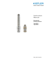
Fig. 1: Water-cooled cylinder pressure sensors
2.1 Techical data and documentation
Data sheets are available on www.kistler.com.

Water cooled piezoelectric sensors
7061_002-027e-09.23Page 6
2.2 Principle of operation
The sensor membrane converts the measured pressure
into a force which is applied to the piezoelectric measu-
ring element. In the piezoelectric crystal package this
force generates an electrostatic charge proportional to the
load. An electrode collects this charge and supplies it to
the sensor connector, then via the piezoelectric cable; the
chargeamplierconvertsthischargeintoanelectricvol-
tage for measurement and processing.
The piezoelectric principle is most suited for measure-
ments of fast, dynamic and quasi-static pressure changes
and thus plays a key role in engine pressure measure-
ments.
Fig. 2: Cross section of a piezoelectric water cooled
sensor

Preface
Page 77061_002-027e-09.23
2.3 Requirements to water cooling
The use of cooling system Kistler Type 2621 is highly
recommended. It can supply up to ten water cooled
piezoelectric sensors (depending on the heat load created
by the application) with the optimum quantity of water,
at the right pressure and constant temperature. This
facilitates measurements with absolute reproducibility and
best lifetime of the piezoelectric sensors.
Cooling system specication
Coolant temperature: 50 °C
Coolantowrate: 0.3to0.5l/min
Coolant pressure: 1.7 ±0.2 bar
Cooling uid specication
Demineralized water according to norm VDE-Norm 0510
CoolinguidadditiveGlysantinG30orG40(donotmix
with each other)
Mixing ratio: 1 part additive with 4 parts demineralized
water (Frostproof down to -9°C)
For more information, please refer to instruction manu-
al of cooling unit Type 2621
Never connect the piezoelectric sensor to an open coo-
ling system with water from the mains supply. This water
source contains calcium and lime deposits and will ac-
cumulate inside the piezoelectric sensor – impacting the
sensitivity and even in the worst case, block the cooling
channel inside the piezoelectric sensor.
2.4 Precautions for water cooling
The water cooling system must be turned on before the
engine is started. The reason is that if the water cooling
system is turned on after the engine has been running for
a period of time, the piezoelectric sensor may be dama-
ged due to the low temperature coolant encountering the
hotpiezoelectricsensor(thermalshockeect).
Do not start the water cooling system if the temperature
of the piezoelectric sensor is high.

Water cooled piezoelectric sensors
7061_002-027e-09.23Page 8
If the water cooling system fails and cannot work normally,
the engine and water cooling system should be shut down
immediately to prevent the water cooling system from
working intermittently, thus damaging the sensor. To con-
tinue using the water cooling system, stop the engine until
the temperature of the piezoelectric sensor drops to ap-
proximately the same temperature as the coolant.
During the operation of the water cooling system, it must
be ensured that the water hoses and tubes are not con-
stricted–freeowofthecoolantisessential.
Before using the sensor without water cooling, empty the
water from the sensor, ush it with demineralized water
and blow it out very carefully with compressed air. The
same procedure should be applied before storing the
sensor when not in use.

Installation of the piezoelectric sensor
Page 97061_002-027e-09.23
3. Installation of the piezoelectric sensor
3.1 General information
The accuracy of a measurement and quality of the data
are highly dependent on careful installation of the piezo-
electric pressure sensor.
Thesensorboremustbemachinedtothespeciedtole-
rances.
Thespeciedtighteningtorqueofthepiezoelectricsensor
must be observed.
3.2 Direct installation
Direct installation requires the least installation space. Of
course, a direct installation is only possible if it is not ne-
cessary to cross any water or oil galleries in the cylinder
head casting.
In the case of repeated mounting and dismounting of
the sensor, there is the risk of damaging the sealing me-
chanism and thread of the mounting bore. Typically, the
cylinder head material is softer than that of the sensor.
Before mounting the sensor in the bore, also to facilitate
dismounting it at the end of the test, it is recommended
to coat thread and sealing part of the piezoelectric sen-
sor with high temperature resistant grease (for example
MOLYKOTE HSC plus or Metaux 70-81). Do not apply
any grease on the membrane.
3.3 Installation with sleeve
In the case where the cylinder can only be accessed via
an oil or cooling water gallery, a mounting sleeve is ne-
cessary to provide adequate sealing for the installation. At
the front, the sleeve is screwed and sealed with a sealing
ringattherear,sealingisachievedusingO-ringsand/or
Loctite compound (Loctite 648 for shaft-hub, Loctite 290
for thread).

Water cooled piezoelectric sensors
7061_002-027e-09.23Page 10
Benetsofusingamountingsleeve:
Precise sensor bore inside the sleeve
Machining of the bore for the mounting sleeve is
simplied
The mounting sleeve has the required strength to en-
sure that the sealing part can resist wear. This allows
the sensor to be mounted and dismounted repeatedly
without restrictions
When removing the sensor, the mounting sleeve pre-
ventscoolinguidfrompassingfromleakingintocom-
bustion chamber
Disadvantages of using a mounting sleeve:
Can inuence on the cylinder head cooling perfor-
mance (depending on size and position of the sleeve
with respect to the water cooling channels)
3.4 Installation examples
Fig. 3: Left:sleevemountingwithmembraneush;
right: direct mounting with small gas channel

Installation of the piezoelectric sensor
Page 117061_002-027e-09.23
3.5 Machining the mounting bore
When preparing the sensor bore, ensure that the thread
is concentric in relation to its individual steps. The sealing
part must be completely at. Refer to the specications
and tolerances stated on the datasheet of the sensor.
All machining steps with the drill, milling cutter, reamer
and screw tap must be performed with the work held se-
curely in the same position.
3.6 Mounting the water hose on the cooling pipe
Soak the end of the rubber hose in boiling water for seve-
ral seconds – this allows expansion via heating to assist
tting,thenttherubberhoseonthecoolingpipeofthe
sensor. With this procedure it is not necessary to rotate
therubberwaterhosebackandforthwhilstttingasthis
creates a risk of loosening the cooling pipe. If a cooling
pipe becomes loose, it must be unscrewed completely
– then follow the procedure as mentioned in the chapter
"maintenance".

Water cooled piezoelectric sensors
7061_002-027e-09.23Page 12
3.7 Check points before installation
Water leakage - After connecting the rubber hoses to
the cooling pipes of the sensor, operate the cooling
system and check that there is no leakage
Piezoelectric cable - If the piezoelectric cable connec-
ted to the sensor is loose it must be retightened. Note
that the piezoelectric cable of sensor type 6041B is ac-
cessible only after removing one of the water cooling
pipes (see chapter "maintenance")
Carefully check the piezoelectric cable for damage
over its full length, and if necessary replace it comple-
tely. The insulation resistance of sensor and piezoelec-
tric cable should be checked by connecting the insu-
lation tester at the end of the piezoelectric cable. The
minimumrequirementatroomtemperatureis10E13Ω
Sensor seal ring - The sensor seal ring must al-
ways be applied to the sensor as shown in Figure
4. If the seal ring is damaged, it should be replaced
Fig. 4: Seal ring of a shoulder sealing sensor
Mounting bore - Check the condition of the mounting
bore;itmustbemachinedtothespecieddimensions
and tolerances as described in the datasheet, and also
clean and dry prior to installation

Installing the sensor into the bore
Page 137061_002-027e-09.23
4. Installing the sensor into the bore
Feed the piezoelectric cable and both rubber hoses
through the mounting wrench, and then t the mounting
wrench on the hex of the sensor. If you are using the slot-
ted mounting wrench Type 1300A73 for sensor Type 6041,
pay attention to proper positioning of the piezoelectric
cable and rubber water hoses in the slot (otherwise
danger of compression damage). Make sure the pins
are properly engaged into the small bores of the sensor.
Before installing the sensor in the bore, the thread and
sealing part should be lubricated with high-temperature
resistant grease (for example MOLYKOTE HSC plus or
Metaux70-81).Thiswillfacilitatedismountingthesensor
from the bore post-testing.
During installation and disassembly, the piezoelectric
cable and rubber water hoses should be rotated with the
mounting wrench to avoid damage of the piezoelectric
cable and the possibility of inadvertently loosening the
cooling pipes. During use, pay attention to protect the
sensor piezoelectric cable. Do not squash, twist or pull the
piezoelectric cable.
Screw the sensor hand-tight and then use the torque
wrenchfortighteningtotherequiredvalueasspeciedin
the datasheet of the sensor.
When the sensor installation is completed, connect the
water hoses to feed and return manifolds of the water
cooling system.
Fig. 5: Assembly with water cooled sensor and moun-
ting wrench for installation

Water cooled piezoelectric sensors
7061_002-027e-09.23Page 14
5. Piezoelectric sensor cable routing
The piezoelectric cable of the sensor must be routed to
avoid other high-frequency, or power cables, as much
as possible, e.g. ignition or fuel injection system cabling,
dynamometer or motor power cables. If this cannot be
avoided, the piezoelectric cables should be kept perpen-
dicular to the high-frequency signal lines to reduce signal
interference.
There must be no mechanical tension on the piezoelec-
tric cable. It is absolutely essential to avoid deformation
caused by sharp bends. During use, pay attention to pro-
tect the piezoelectric cable: do not squash, twist or pull
it. Ensure the cleanliness of the piezoelectric cable con-
nector. Do not allow water, oil, dust, or other dirt in the
vicinity of the cable interfaces. If the piezoelectric con-
nector becomes contaminated during use, use an elec-
tronic cleaning spray to clean it. Use the cap to cover and
protect the piezoelectric connector when the piezoelectric
sensor is not in use.

Setting up the measuring chain
Page 157061_002-027e-09.23
6. Setting up the measuring chain
6.1 Connecting the piezo electric cable to charge amplier
Fig. 6: Basic arrangement of a measuring chain
Piezoelectric sensor cable, adapter, and piezoelectric ex-
tension cable should be connected before connecting its
endtotheinputsocketofthechargeamplier.
Makesurethechargeamplierisnotinmeasuringmode
when connecting the piezoelectric sensor cable to the
charge amplier input. This avoids potential damage to
sensitive electronic input circuitry.
The length of piezoelectric cables between sensor and
charge amplier should not exceed 10 m. Interference
from extraneous voltages and ground loop issues at the
test cell can be avoided, or reduced, by using a short pie-
zoelectriccableandpositioningthechargeamplierclose
to the piezoelectric sensor.
6.2 Selecting the sensor sensitivity
Since Kistler water cooled sensors can be used with wa-
ter cooling or uncooled, the sensitivity at 50 °C should be
used if water cooling is used, and the sensitivity at 250 °C
should be used in the case of uncooled operation.
Operation with water cooling is recommended to achieve
the highest accuracy of the pressure measurement (most
stable sensor sensitivity regardless of the engine opera-
ting condition, no load change drift).

Water cooled piezoelectric sensors
7061_002-027e-09.23Page 16
7. Dismounting and maintenance
7.1 Dismounting
Allow the cylinder head to cool down before removing the
sensor from the mounting bore. Dismount in reverse order
than installation:
Switchothewatercoolingsystem
Disconnect the water hoses of the sensor from feed
and return manifold
Disconnect the piezoelectric sensor cable from the
chargeamplier/fromtheextensioncable
Feed the piezoelectric sensor cable and both rubber
hoses through the mounting wrench, carefully slide
it to the sensor, and then t the mounting wrench
on the hex of the sensor. If you are using the slotted
mounting wrench Type 1300A73 for sensor Type 6041,
pay attention to properly position piezoelectric cable
and both rubber water hoses in the slot (otherwise
danger of squeezing). Make sure the pins are properly
engaged into the small bores of the sensor
Unscrew the sensor from the bore
7.2 Maintenance
Piezoelectric pressure sensors are precision instruments;
theywilldelivermeasurementsinthespeciedaccuracy
range only if they are handled with care. Special attention
is required for the front part of the sensor – the membrane
and sealing area must always be protected against me-
chanical damage.
Do not tap impact or shock the front surface of the sensor
with metal or any other objects – this will help to avoid
damage to the membrane.
Visual inspection - Sensor, piezoelectric cable and
cooling pipes should be carefully inspected for anoma-
lies (damage, soot deposits, overheating due to com-
bustion gas leakage)

Dismounting and maintenance
Page 177061_002-027e-09.23
Cleaning - After the sensor is disassembled from the
engine, combustion deposits may be cleaned with a soft
brush and Isopropyl alcohol (CAS Number 67-63-0).
The front part of the sensor (membrane) cannot be
cleaned using mechanical means such as brushing,
sand blasting, grinding, etc. as this will irreparably da-
mage the membrane and thus the sensor
Visual inspection - After cleaning, see above
Insulation check - The insulation resistance of the
sensor with piezoelectric cable should be checked by
connecting the insulation tester Type 5493 at the end
of the piezoelectric cable. The requirement at room
temperature is 10E13 Ω. If the value is too low, all
piezoelectric connectors should be disconnected and
the insulators cleaned with electronic cleaning spray
Kistler Type 1003 or a similar product. Do not touch the
connectorinsulatorwithbarengersanddonotblowit
out with shop compressed air
Pressure calibration - Recalibration is recommended
every 200 hours of operation or after each disassembly
of the sensor from the cylinder head
Exchange of components - It is possible to replace
the sealing ring, the piezoelectric cable, and the coo-
ling pipes. Material numbers are listed in the datas-
heet of the sensor. The replacement of the sealing ring
should be done by Kistler
Removing the cooling pipes Types 1225,
1225A1/A2/A5
Necessary material
-Hot-air blower with variable temperature
-Open ended wrench 3 mm AF
-Solvent iso-propanol or a similar product
Procedure:
-Remove the rubber hose from the cooling pipe
-Locally heat by hot-air blower the contact area of the
cooling pipe with the sensor body (max. air temp.
200 °C). Do not expose the piezoelectric cable to
the hot air (risk of overheating)
-Simultaneously unscrew the cooling pipe with the
open ended wrench 3 mm AF
-With the means of a small brush, clean the thread
M3x0.35 of the cooling pipe with iso-propanol or a
similar product
-Clean the M3x0.35 bores on the sensor: there
should not be any Loctite residue left in the cooling
channel. To achieve this, wash out the bore with
Isopropyl alcohol (CAS Number 67-63-0) or a similar
product using a small brush. Gently blow out the in-
dividual bores using compressed air

Water cooled piezoelectric sensors
7061_002-027e-09.23Page 18
Removing a defective piezoelectric cable
Necessary material:
-Open ended wrench 4 mm (Type 1300A35).
Unscrew the piezoelectric cable connector by using an
open ended wrench 4 mm AF. If the connector cannot
be unscrewed with the wrench 4 mm AF, remove and
clean the second cooling pipe as described above
Installing a new piezoelectric cable
Necessary material:
-Spare piezoelectric cable
-Open ended wrench 4 mm AF (Type 1300A35)
-Isolation tester Kistler Type 5493
-Cleaning spray Kistler Type 1003 or similar product
Procedure:
-Measure the insulation of the piezoelectric cable, it
mustreach10E13Ω.Iflowerthanthisvalue,clean
both piezoelectric connectors of the cable with the
cleaning spray
-Clean the piezoelectric sensor connector on the
sensor using cleaning spray Kistler Type 1003
-Ensure that the repective O-ring is mounted on the
piezoelectric sensor connector
-Screw the piezoelectric cable on the piezoelectric
sensor connector
-Check the insulation of the assembly piezoelectric
sensor and piezoelectric cable again, it must reach
10E13Ω
Installing the cooling pipes Type 1225,
1225A1/A2/A5
-The piezoelectric cable should be connected to the
sensor before installing the cooling pipes Type 1225
to the sensor
-Visually inspect the piezoelectric sensor and the
cooling pipes to ensure that there is no remaining
Loctite residue left in the cooling channels
Necessary material:
-Spare cooling pipes Type 1225
-Open ended wrench 3 mm AF
-Loctite 510
Procedure:
-Using a toothpick, slightly moisten the tapped bore
M3 and male thread M3 of the cooling pipe with Loc-
tite 510
-Screw the cooling nipple into the bore
-Tighten the cooling pipe using the open ended
wrench 3 mm AF
-Clean the Loctite residue with iso-propanol or a si-
milar product
/
