17
Installation and Operation of Product Holding Cabinets
INSTALLATION
INSTRUCTIONS
UNPACKING UNIT
1. Inspect the shipping carton and/or container,
carefully noting any exterior damage on the delivery
receipt.
2. Contact the carrier immediately and le a damage
claim with them. Save all packing materials when
ling a claim. Freight damage claims are the
responsibility of the purchaser and are not covered
by the warranty.
3. Unpack and Inspect the unit for damage.
4. Report any dents or breakage to the source of
purchase immediately.
CAUTION: Do not attempt to use unit if damaged.
5. Remove all materials from the unit interior.
6. If the unit has been stored in extremely cold area,
wait a few hours before connecting the power.
INSTALLATION CODES AND STANDARDS
In the United States, the PHU must be installed in
accordance with the following:
1. State and local codes.
2. National Electrical Code (ANSI/NFPA No. 70, latest
edition) available from the National Fire Protection
Association, Batterymarch Park, Quincy, MA
02269.
3. Vapor Removal from Cooking Equipment, (NFPA-
96, latest edition) available from NFPA.
In Canada, the PHU must be installed in accordance
with the following:
1. Local codes.
2. Canadian Electrical Code (CSA C22.2 No. 3, latest
edition) available from the Canadian Standards
Association, 5060 Spectrum Way, Mississauga,
Ontario, Canada L4W 5N6.
For CE Units, the PHU must be installed in accordance
with the following:
1. Local codes.
2. European (IEC/CENELEC) Electrical Code
UNIT PLACEMENT
• Do not install the unit next to or above heat sources,
such as oven or deep fat fryer.
• Install the unit on a level countertop surface.
• The power outlet should be located so that plug is
accessible when the unit is in place.
• The FWM is designed for access from either side.
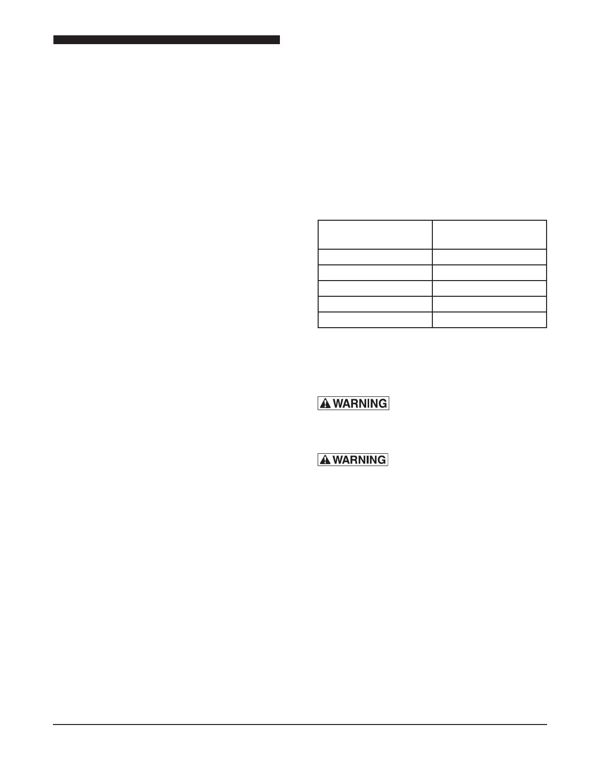
Clearance Requirements
CLEARANCE
REQUIREMENT
CLEARANCE
IN INCHES
Top 0
Right Side 1
Left Side 1
Bottom 0
Rear OPEN
• Proper airow around the unit cools its electrical
components. With restricted airow, the unit may
not operate properly and life of the electrical parts
is reduced.
: To avoid risk of electrical
shock or death, this unit must be grounded
and plug must not be altered.
: Before connecting the unit to
the electrical supply, verify that the electrical
connection agrees with the specications on
the data plate. Failure to comply with this
procedure can cause property damage, injury
or death.
EARTHING INSTRUCTIONS
THE UNIT MUST BE GROUNDED. Grounding reduces
risk of electric shock by providing an escape wire for
the electric current if an electrical short occurs. This
unit is equipped with a cord having a grounding wire
with a grounding plug. The plug must be plugged into
a receptacle that is properly installed and grounded.
Consult a qualied electrician or service agent if
grounding instructions are not completely understood,
or if doubt exists as to whether the oven is properly
grounded.


