Page is loading ...

Instructional Leaet IL019116EN
Effective July 2016
Supersedes December 2015
Installation guidelines for users of Magnum DS
Low-Voltage Front-Access Switchgear Assemblies
for seismic applications
A representative Type Magnum DS
®
Low-Voltage
Front-Access Switchgear Assembly was attached
to a seismic table and shaken to simulate the
effects of an earthquake. The test exceeded the
requirements of the 2012 International Building
Code (IBC), the 2013 California Building Code (CBC),
and OSHPD Seismic Pre-certification (OSP). The
following guidelines were developed as a result of
that test program, and they apply to standard and
arc-resistant switchgear:
1. When Magnum DS Front-Access Switchgear
is subjected to an earthquake, it pulls on its
foundation. The importance of an adequate
foundation cannot be over emphasized; in fact,
proper mounting is the single most important
factor in withstanding a seismic event. The
foundation must be level and continuous
under the entire switchgear assembly. The
foundation must be designed to withstand
the reaction loads imposed on it by the
equipment. The foundation must be designed
to hold a quantity of two ½-13 SAE Grade 5
bolts per section or four ½-13 SAE Grade 5
bolts per section if not mounting switchgear
to a wall or six ½-13 SAE Grade 5 bolts per
back-to-back section if mounting switchgear
back-to-back. The anchoring system must be
strong enough to prevent “pull-out” of these
bolts. The wall behind the switchgear must
be designed to hold a quantity of two ½-13
SAE Grade 5 bolts per section. The anchoring
system must be strong enough to prevent
“pull-out” of these bolts. Both anchoring
systems, wall, and foundation should be put
into place prior to switchgear installation
to reduce effort associated with anchoring.
Welding to embedded steel members is
acceptable, provided the weld strength is
equivalent to that of four SAE Grade 5 bolts
specified. For nuclear installations, weld per
AWS D1.1, alternatively, welding procedures
and personnel qualifications may be performed
IAW ASME BPVC Section IX and the
inspections be performed IAW AWS D1.1,
and/or D1.3 and/or D9.1. See foundation
drawings provided for the specific project
to identify anchoring locations.
2. Magnum DS Front-Access Switchgear is
supplied with wall braces that must be used
to anchor the rear of the switchgear to a wall
(see Figure 4).
3. When Magnum DS is subjected to an
earthquake, it moves. The amount of motion
depends on the magnitude of the earthquake.
Eaton Pow-R-Way
®
and non-segregated phase
bus ducts, and their associated switchgear
flanges have been seismically qualified as
a system. If other types of top entry, i.e.,
conduits, are necessary, attachments must be
capable of accommodating a 3-inch front-to-
back and side-to-side (6 inches peak-to-peak)
cabinet motion.
4. Center of gravity
For seismic calculations, the following
dimensions should be used to locate
the approximate center of gravity for
Magnum DS switchgear. They are applicable
to all types of line-ups:
Vertical 60 inches
From left-to-right Center of line-up
From front One-half the depth
of the switchgear
Enclosure weights are found on the equipment
drawings provided for the specific project. Add
breaker weights to enclosure weight.
5. When a switchgear assembly is separated
into groups of vertical sections for shipment,
the user must be sure to install all of the inter-
unit tie bolts (see drawing 9253C18). Failure
to join the shipping groups together properly
could result in damage to the equipment
during an earthquake.
6. It is recommended that incoming power
cables be lashed together at least every
4 feet within the switchgear.
7. The drawout Magnum DS power circuit
breakers should always remain in the
connected position or they should be
secured remote from the switchgear.
8. The user should provide storage areas to
secure mobile pieces of equipment (such as
breaker lifting trucks, spare breakers, hand
trucks, etc.) away from the switchgear so it
is not damaged by being bumped during an
earthquake. When the optional top-of-gear
traveling circuit breaker lifter is provided, it
must be secured in place with the hardware
provided when not in use. Refer to the
operating instructions provided with the
switchgear for the details of this procedure.

2
Instructional Leaet IL019116EN
Effective July 2016
Installation guidelines for users of Magnum DS
Low-Voltage Front-Access Switchgear Assemblies
for seismic applications
EATON www.eaton.com
Plan view
Floor steel
Floor steel
Rear wall
c
d
b
c b
c
a
c
e
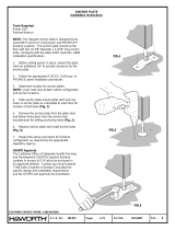
Figure 1. Welding of indoor structures to imbedded floor steel—front-access Magnum switchgear
a
0.19 inches (4.8 mm) weld, 4.00 inches (101.6 mm) long at two places on front of each section starting 0.50 inches (12.7 mm) from each edge of structure.
See Figure 3 for front access wall brace weld instructions.
b
Internal bracket on each end of line up to be plug welded to floor steel.
c
For nuclear installations, weld per AWS D1.1, alternatively, welding procedures and personnel qualifications may be performed IAW ASME BPVC Section IX and the inspections
be performed IAW AWS D1.1, and/or D1.3 and/or D9.1.
d
0.19 inches (4.8 mm) weld, 4.00 inches (101.6 mm) long at two places on rear of each section starting 0.50 inches (12.7 mm) from each edge of structure if wallmount brace is not being used.
e
Sufficient clear space, between the wall and the rear of the switchgear, should be provided to allow for proper attachment of the switchgear to the pad.

3
Instructional Leaet IL019116EN
Effective July 2016
Installation guidelines for users of Magnum DS
Low-Voltage Front-Access Switchgear Assemblies
for seismic applications
EATON www.eaton.com
Plan view
Floor steel
Floor steel Floor steel
Switchgear 1
Switchgear 2
Switchgear 1 Switchgear 2
2.50
(63.5)
a
c
b
c
b
c
b
c
b
c
a
c
c
d
Figure 2. Welding of indoor structures to imbedded floor steel—front-access back-to-back Magnum switchgear
a
0.19 inches (4.8 mm) weld, 4.00 inches (101.6 mm) long at two places on front of each section starting 0.50 inches (12.7 mm) from each edge of structure.
b
Internal bracket on each end of line-up to be plug welded to floor steel.
c
For nuclear installations, weld per AWS D1.1, alternatively, welding procedures and personnel qualifications may be performed IAW ASME BPVC Section IX and the inspections
be performed IAW AWS D1.1, and/or D1.3, and/or D9.1.
d
0.19 inches (4.8 mm) weld, 4.00 inches (101.6 mm) long at two places on rear of each section on Switchgear 1 only, starting 0.50 inches (12.7 mm) from each edge of structure where indicated.

4
Instructional Leaet IL019116EN
Effective July 2016
Installation guidelines for users of Magnum DS
Low-Voltage Front-Access Switchgear Assemblies
for seismic applications
EATON www.eaton.com
2.00
(50.8)
Elevation view
Wall steel
99.00
(2514.6)
Wallmount brace
a
b
c
Figure 3. Welding of indoor structures to imbedded wall steel—front-access Magnum switchgear
a
0.19 inches (4.8 mm) weld, 4.00 inches (101.6 mm) long at two places on top of each section starting 0.50 inches (12.7 mm) from each edge of structure.
See Figure 1 for front-access front compartment bottom pan weld instructions.
b
For nuclear installations, weld per AWS D1.1, alternatively, welding procedures and personnel qualifications may be performed IAW ASME BPVC Section IX
and the inspections be performed IAW AWS D1.1, and/or D1.3 and/or D9.1.
c
A distance of 2.00 inches (50.8 mm), between the wall and the rear of the switchgear, is required to properly secure Front-Access Switchgear when using the rear wallmount brace.

5
Instructional Leaet IL019116EN
Effective July 2016
Installation guidelines for users of Magnum DS
Low-Voltage Front-Access Switchgear Assemblies
for seismic applications
EATON www.eaton.com
a
c
c
Detail A
Front compartment
seismic brace
(shipped installed
at the ends of the
line-up only!)
Seismic wallmount brace
(shipped installed on gear)
Detail B
A
B
1/2-inch tie-down
hardware
1/2-inch tie-down
hardware
1/2-inch tie-down
hardware
a
b
Figure 4. Magnum switchgear front-access rear frame seismic wall brace and front compartment seismic brace information
a
Secure enclosure to pad and/or wall with Grade 5 hardware.
b
Front compartment must be secured to pad for both rear frame wallmount and rear frame floormount applications.
c
A distance of 2.00 inches (50.8 mm), between the wall and the rear of the switchgear, is required to properly secure Front-Access Switchgear when using the rear wallmount brace.

6
Instructional Leaet IL019116EN
Effective July 2016
Installation guidelines for users of Magnum DS
Low-Voltage Front-Access Switchgear Assemblies
for seismic applications
EATON www.eaton.com
a
b
Detail A
Front compartment
seismic brace
(shipped installed
at the ends of the
line-up only!)
Back-to-back brace
(shipped installed on gear)
Detail B
A
B
1/2-inch tie-down
hardware
1/2-inch tie-down
hardware
C
1/2-inch tie-down
hardware
Detail C
Rear frame floor brace
(shipped installed on
Switchgear 1 only)
Switchgear 1
Switchgear 2
a
b
a
Figure 5. Magnum switchgear front-access back-to-back seismic brace information
a
Secure each enclosure to pad and/or to adjacent back-to-back switchgear line-up with Grade 5 hardware.
b
Front compartments of both switchgear line-ups must be secured to pad for back-to-back applications.

7
Instructional Leaet IL019116EN
Effective July 2016
Installation guidelines for users of Magnum DS
Low-Voltage Front-Access Switchgear Assemblies
for seismic applications
EATON www.eaton.com
Detail A
Seismic wallmount brace
(shipped installed on gear)
A
1/2-inch tie-down
hardware
IMPORTANT: When using the
wallmount brace, plenum must
be installed on switchgear after
the switchgear is secured to wall.
a
c
Figure 6. Magnum switchgear front-access rear frame seismic wall brace arc-resistant specific information
a
Secure enclosure to pad and/or wall with Grade 5 hardware.
b
Front compartment must be secured to pad for both rear frame wallmount and rear frame floormount applications (see Detail B on Figure 4).
c
A distance of 2.00 inches (50.8 mm), between the wall and the rear of the switchgear, is required to properly secure Front-Access Switchgear when using the rear wallmount brace.

Eaton
1000 Eaton Boulevard
Cleveland, OH 44122
United States
Eaton.com
© 2016 Eaton
All Rights Reserved
Printed in USA
Publication No. IL019116EN / Z18392
July 2016
Eaton is a registered trademark.
All other trademarks are property
of their respective owners.
Installation guidelines for users of Magnum DS
Low-Voltage Front-Access Switchgear Assemblies
for seismic applications
Instructional Leaet IL019116EN
Effective July 2016
Detail A
A
1/2-inch tie-down
hardware
Rear frame floor brace
(shipped installed on gear)
a
b
Figure 7. Magnum switchgear front-access rear frame seismic floor brace information
a
Secure enclosure to pad with Grade 5 hardware.
b
Sufficient clear space, between the wall and the rear of the switchgear, should be provided to allow for proper attachment of the switchgear to the pad.
/