Tripp Lite Minicom Power-On Cable Owner's manual
- Type
- Owner's manual

Power On Cable
User Guide
1111 W. 35th Street, Chicago, IL 60609 USA
www.tripplite.com/support
Copyright ©2012 Tripp Lite. All rights reserved.

Power On Cable
1
Table of Contents
1. Introduction...................................................................................................................2
2. The PoC system ...........................................................................................................2
3. Pre-installation guidelines.............................................................................................2
4. System components .....................................................................................................3
5. Connecting the PoC (standalone).................................................................................3
Connecting a PoCto the IP Control......................................................................................4
Connecting a PoCto the PX................................................................................................4
6. LED indicators on the PoC............................................................................................5
7. Using the PoC Management Utility...............................................................................6
Names tab..........................................................................................................................7
Redundancy tab..................................................................................................................8
Groups tab..........................................................................................................................9
8. Operating the system..................................................................................................10
9. Technical specifications..............................................................................................11
AppendixA: TheRS232 control protocol:...........................................................................12

USER GUIDE
2
1. Introduction
The Power on Cable (PoC) from Minicom is a unique “power cord” with a zero U
form-factor. It can switch on, off and power cycle via serial command to between 1
and 99 servers. Works with Minicom’s IP Control, PX or standalone.
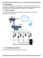
2. The PoC system
The figure below illustrates the PoC system, showing the POCs connected to
servers and to the IP Control.
Figure 1 PoC + IP Control configuration
3. Pre-installation guidelines
Switch off the computers to be connected with PoCs.
LAN/WAN
Server 1 Server 2 Server 3 Server 4
IP CONTROL
KVM switch
POCs
User over IP

Power On Cable
3
4. System components
The PoC system comes with:
1 PoC
1 Transmitter
1 Transmitter cable for IP Control
1 rack mount
5. Connecting the PoC (standalone)
Connect the PoC as illustrated in Figure 2.
1. Slot the Transmitter into the side of the PoC furthest away from the LEDs.
Ensure the arrows on the Transmitter and PoC are facing each other.
2. Connect the Serial cable’s RJ11 connector to the Transmitter port and connect
the Serial cable’s RJ45 connector to the server’s Serial port using a RJ45 to
Serial connector converter.
3. Connect the PoC’s cable to the server’s power port.
4. Connect the supplied cable to the PoC and to a power outlet. The PoC can work
on 220V our 110V.
Figure 2 Connecting the POC
To server’s
power port
To power outlet
To POC
POC
Transmitter slotted into the
PoC
To Transmitter
port
To server’s
serial port
Serial cable
RJ45
RJ11

USER GUIDE
4
Connecting a PoC to the IP Control
Connect to the IP Control using the PoC Transmitter as follows.
1. Slot the Transmitter into the side of the POC furthest away from the LEDs.
Ensure the arrows on the Transmitter and PoC are facing each other.
2. Connect the Serial connector to Serial port of the IP Control. See Figure 3.
3. For the rest of the IP Control connections, and to operate the IP Control system
see the IP Control User Guide.
Figure 3 Power on Cable Transmitter connections
Connecting a PoC to the PX
Connect to the PX using the PoC Transmitter as follows.
1. Slot the Transmitter into the side of the POC furthest away from the LEDs.
Ensure the arrows on the Transmitter and PoC are facing each other.
2. Connect the 26 pin connector of the supplied PX to PoC cable to the 26 pin port
of the PX. See Figure 4.
3. Connect the PX to PoC cable Video connector to the server’s Video port and
connect the USB connector to the server’s USB port.
4. For the rest of the PX connections, see the PX User Guide.
IP CONTROL
To Serial port
PoCs
Transmitter slotted
into a PoC

Power On Cable
5
Figure 4 Power on Cable to PX connections
6. LED indicators on the PoC
There are 2 LEDs.
The green LED indicates the PoC is connected to a power outlet. The red LED
indicates that the server is powered on. Both LEDs flash when the Transmitter unit
communicates with the serial device.
LAN/WAN
To Video
port
To USB
port
Server
To power
port
To Transmitter
port
PX to PoC
cable
User over IP
To 26 pin port
port

USER GUIDE
6
7. Using the PoC Management Utility
When PoCs are connected to the IP Control or the PX, use the web interface to
configure the PoCs.
For standalone applications, use the PoC Utility or a standard hyperterminal to send
commands to the PoCs. (The syntax for the commands can be found in Appendix A
on page 12).
1. Download the PoC Management Utility program from our website at:
http://www.minicom.com/phandlm.htm
2. Install the PoC Management Utility program on your computer.
3. Open it by either clicking the shortcut on the desktop , or choose
Start/Programs/PoC Management/PoC Management. The PoC Management
Utility appears.
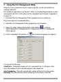
4. Click Commands/Configuration or the General tab appears, see Figure 5.
Figure 5 General tab
You can do the following:
Total PoCs – Change the number of PoCs connected from 1 to 99 units. Click
Save. The number of PoCs selected appears in the Names tab.
Auto Numbering - This will automatically number all the PoCs in the system.
Warning! This will erase any names and groups in the system. Click OK.

Power On Cable
7
Set ID – You can choose to autonumber just some of the PoCs and configure the
names of other PoCs yourself as explained below in the names tab. Click Set ID.
Blink ID - See which POC is connected by blinking the LEDs of a defined PoC
and specifying the blink time from 1-99 seconds. Click Blink.
Delay Time – Set the time delay between each PoC in the system shutting down.
For example if the delay time is 10 seconds, then there is a delay of 10 seconds
between each PoC shutting down when the whole system is shut down. Click Save.
Reboot time - Choose the time delay from 1-99 seconds for each PoC to reboot,
when sending a reboot command to the whole system. Click Save.
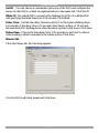
Names tab
Click the Names tab, the following appears.
Figure 6 Names tab
Give the PoCs individual names and click Save.

USER GUIDE
8
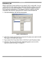
Redundancy tab
Where a server has 2 power outlets you can connect 1 PoC to each outlet. You can
combine the PoCs into a single group so that in the Operation window you see the
group of pocs as a unit and not separately. You then power manage the group of
PoCs and not the individual PoC. For example if PoCs ID 5 and ID 6 are both
connecetd to the Lab server, group PoCs ID 5 and ID 6 and call them Lab.
1. Click the Redundancy tab, the following appears.
Figure 7 Redundancy tab
2. In the PoCs column select the PoCs connected to the same server and click Add.
They appear in the right hand column.
3. Type a name in the Group Name field, or click New to give the group a name.
4. Click Save. The group with the name underneath appears as an icon in the
Operation window see Figure 9 on page 10.

Power On Cable
9
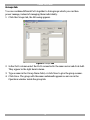
Groups tab
You can combine different PoCs together to form groups which you can then
power manage, instead of managing them individually.
1. Click the Groups tab, the following appears.
Figure 8 Groups tab
2. In the PoCs column select the PoCs connected to the same server and click Add.
They appear in the right hand column.
3. Type a name in the Group Name field, or click New to give the group a name.
4. Click Save. The group with the name underneath appears as an icon in the
Operation window inside the group tab.

USER GUIDE
10
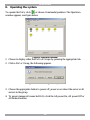
8. Operating the system
To operate the PoCs, click or choose Commands/operation. The Operation
window appears, see figure below.
Figure 9 Operation window
1. Choose to display either the PoCs or Groups by pressing the appropriate tab.
2. Click a PoC or Group, the following appears.
Figure 10 Power management options
3. Choose the appropriate button to power off, power on or reboot the server or all
servers in the group.
4. To power manage all connected PoCs, click the All power On, All power Off or
All Reboot buttons.

Power On Cable
11
9. Technical specifications
Specifications
Electrical Rating
Input Voltage
90 - 260VAC
Input Frequency 44 – 66Hz
Max. Output Current 10Amp
Connectors
Input Receptacle C14
Output Power Cable C13 + 150cm Cable
Communication Ports IrDA Transmit & Receive
Communication
Protocol
Baud Rate 1200bps
Distance 4 – 8m
LED Indicator
Green LED Input Power Status
Red LED Output Power Status
Operation & Environment
Operating Temperature 0ºc to 50ºc /32ºf to 122ºf
Relative Humidity 0 - 95%
Storage Temperature -15 ºc to 50 ºc / 5 ºf to 122 ºf
Plastic enclosure
Basic unit 92x42.7x29.5mm/3.62x1.68x1.16inch
Multiple Devices 92x44.3 (1”U”)x29.5mm/3.62x1.74x1.16inch

USER GUIDE
12
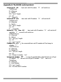
Appendix A: The RS232 control protocol:
Switch on ID “X” – basic unit with ID number “X” will switch on.
^MS005xxx,I
M : Minicom
S : Switch
005 : "xxx,I" length
xxx : ID
I : Turn ON
Switch off ID “X” – basic unit with ID number “X” will switch off.
^MS005xxx,O
M : Minicom
S : Switch
005 : "xxx,I" length
xxx : ID
O : Turn OFF
Reboot ID “X” Time “Y” – basic unit with ID number “X” will switch off
and after “Y” second it will switch on.
^MR007xxx,yyy
M : Minicom
R : Reboot
007 : "xxx,yyy" length
xxx : ID
yyy : "yyy" second
Change ID to “Y” – the connected basic unit ID number will be change to
number “Y"
^MC007xxx,zzz
M : Minicom
C : Change ID
007 : "xxx,zzz" length
xxx : ID
zzz : Change to number “zzz"
System auto number “X” – in case of cascaded basic units the first one will get
ID number “X” the next one will get ID number “X+1” and so on.
^MA003xxx
M : Minicom
A : Auto Number
003 : "xxx" length
xxx : The first one ID number

Power On Cable
13
Polling ID “X” Time “Y” – basic unit with ID number “X” will blink red LED
about “Y” second..
^MP007xxx,yyy
M : Minicom
P : Polling
007 : "xxx,yyy" length
xxx : ID
yyy : "yyy" second
201204192 • 933201_EN
-
 1
1
-
 2
2
-
 3
3
-
 4
4
-
 5
5
-
 6
6
-
 7
7
-
 8
8
-
 9
9
-
 10
10
-
 11
11
-
 12
12
-
 13
13
-
 14
14


Tripp Lite Minicom Power-On Cable Owner's manual
- Type
- Owner's manual
Ask a question and I''ll find the answer in the document
Finding information in a document is now easier with AI
Related papers
-
Tripp Lite Owner's Manual HDMI over Cat6 Extender Kits and Repeater, 4K/60 Hz Owner's manual
-
Tripp Lite Minicom Power-On Cable Quick start guide
-
-
Tripp Lite TRIPP-LITE 4-Port Presentation Switch Owner's manual
-
Tripp Lite 5UM7017 User manual
-
Other documents
-
Interlogix IFS Power over Coax (PoC) Network Switches POC2502 Series User manual
-
 MuxLab HDMI 4x4 Matrix Switch Kit, HDBT, PoC, 4K/60 Operating instructions
-
Roche cobas b 123 <2> User manual
-
Roche cobas infinity POC Add-on User manual
-
-
-
-
Advantech POC-195 User manual
-
-
