Page is loading ...

Model 3161 Series
Octave Bandwidth
Pyramidal Horn Antenna
User Manual

ETS-Lindgren L.P. reserves the right to make changes to any product described
herein in order to improve function, design, or for any other reason. Nothing
contained herein shall constitute ETS-Lindgren L.P. assuming any liability
whatsoever arising out of the application or use of any product or circuit
described herein. ETS-Lindgren L.P. does not convey any license under its
patent rights or the rights of others.
© Copyright 1992–2010 by ETS-Lindgren L.P. All Rights Reserved. No part
of this document may be copied by any means without written permission
from ETS-Lindgren L.P.
Trademarks used in this document: The ETS-Lindgren logo is a trademark of
ETS-Lindgren L.P.
Revision Record | MANUAL MODEL 3161 | Part #399193, Rev. D
Revision Description Date
A Initial Release September, 1992
B Edits/updates February, 2001
C Edits/updates March, 2002
D Rebrand June, 2010
ii |

Table of Contents
Notes, Cautions, and Warnings ................................................ v
1.0 Introduction .......................................................................... 7
ETS-Lindgren Product Information Bulletin ................................................... 7
2.0 Maintenance ......................................................................... 9
Annual Calibration ......................................................................................... 9
Service Procedures ....................................................................................... 9
3.0 Specifications ..................................................................... 11
Electrical Specifications ............................................................................... 11
Physical Specifications ................................................................................ 12
Power Requirements ................................................................................... 12
Table 1: Model 3161-01 Power Requirements at 1 Meter ................... 13
Table 2: Model 3161-01 Power Requirements at 3 and 10 Meters ..... 14
Table 3: Model 3161-02 Power Requirements at 1 Meter ................... 15
Table 4: Model 3161-02 Power Requirements at 3 and 10 Meters ..... 16
Table 5: Model 3161-03 Power Requirements at 1 Meter ................... 17
Table 6: Model 3161-03Power Requirements at 3 and 10 Meters ...... 18
4.0 Mounting Instructions ....................................................... 19
Mount to 4-TR .............................................................................................. 19
Mount to 7-TR and Mast .............................................................................. 20
Mount to 2x2 Boom ...................................................................................... 21
5.0 Typical Data ........................................................................ 23
Typical VSWR .............................................................................................. 23
Typical Measured and Theoretical Gain and Antenna Factor ..................... 24
Typical Half-Power Beamwidth .................................................................... 25
6.0 Radiated Emissions Measurements ................................ 27
Measure Ambient Field Strength Values ..................................................... 27
Conversion Formulas ................................................................................... 28
Equation 1 ............................................................................................ 28
Equation 2 ............................................................................................ 29
Equation 3 ............................................................................................ 29
Equation 4 ............................................................................................ 29
| iii

Equation 5 ............................................................................................ 29
Equation 6 ............................................................................................ 30
Equation 7 ............................................................................................ 30
Equation 8 ............................................................................................ 30
Equation 9 ............................................................................................ 30
Appendix A: Warranty ............................................................. 31
iv |

Notes, Cautions, and Warnings
Note: Denotes helpful information intended to
provide tips for better use of the product.
Caution: Denotes a hazard. Failure to follow
instructions could result in minor personal injury
and/or property damage. Included text gives proper
procedures.
Warning: Denotes a hazard. Failure to follow
instructions could result in SEVERE personal injury
and/or property damage. Included text gives proper
procedures.
See the ETS-Lindgren Product Information Bulletin for safety,
regulatory, and other product marking information.
| v

vi |
This page intentionally left blank.

1.0 Introduction
The ETS-Lindgren Model 3161 Series Octave Bandwidth Pyramidal Horn
Antenna is designed specifically for emissions and immunity testing over the
1 GHz to 8 GHz frequency range. Characteristics of the Model 3161 Series
include linear polarization, medium gain, medium half-power beamwidth in both
the horizontal and vertical planes, low VSWR over the recommended operating
frequency range, and antenna factors constant within 2 dB. The wide bandwidth
was selected to allow use with octave bandwidth traveling-wave tube (TWT)
amplifiers without the need to change antennas over the band.
Each Model 3161 is furnished with a high performance, low VSWR, Type N
coax-to-waveguide adapter. This adapter limits antenna power-handling capacity,
and may be removed if a power source with waveguide output is available. In
such a configuration, fields in excess of 10,000 V/m at 10 meters are obtainable.
The Model 3161 Series is constructed of aluminum, and then is conversion
coated and painted for protection against corrosion and changes in the weather.
The Model 3161 Series can be used as transmit or receive antennas. The 50 Ω
input impedance is matched to most standard coax cables. In receiving
applications, the antennas are matched to the free space impedance (377 Ω).
Typical performance data is provided beginning on page
23. Methodology for
radiated emissions measurement is described on page 27.
ETS-Lindgren Product Information Bulletin
See the ETS-Lindgren Product Information Bulletin included with your shipment
for the following:
• Warranty information
• Safety, regulatory, and other product marking information
• Steps to receive your shipment
• Steps to return a component for service
• ETS-Lindgren calibration service
• ETS-Lindgren contact information
Introduction | 7

This page intentionally left blank.
8 | Introduction

2.0 Maintenance
Before performing any maintenance,
follow the safety information in the
ETS-Lindgren Product Information
Bulletin included with your shipment.
Maintenance of the Model 3161 Series is
limited to external components such as
cables or connectors.
If you have any questions concerning
maintenance, contact ETS-Lindgren
Customer Service.
WARRANTY
• When not in use, the Model 3161 Series Octave Bandwidth Pyramidal
Horn Antenna should be stored on a shelf face down to keep dust out
of the feed areas.
• If the Model 3161 Series is used outdoors, the antennas should be
checked for water accumulations. Water has a high dielectric constant
and can alter performance.
• If an antenna is dropped, the feed/horn joint should be checked for
misalignment.
Annual Calibration
See the Product Information Bulletin included with your shipment for information
on ETS-Lindgren calibration services.
Service Procedures
For the steps to return a system or system component to ETS-Lindgren for
service, see the Product Information Bulletin included with your shipment.
Maintenance | 9

This page intentionally left blank.
10 | Maintenance

3.0 Specifications
Electrical Specifications
• The VSWR indicated in the following table is that of the pyramidal horn
antenna and coax-to-waveguide adapter. The VSWR of the antenna by
itself is of the order of 1.1:1.
• The maximum continuous power indicated in the following table is
mainly limited by the coax-to-waveguide adapter. The antenna itself is
capable of handling continuous power on the order of 10
4
Watts to
10
7
Watts.
3161-01 3161-02 3161-03
Frequency
Range:
1.0 GHz
to
2.0 GHz
2.0 GHz
to
4.0 GHz
4.0 GHz
to
8.0 GHz
Antenna
Factor:
15.40 dB(1/m) 16.85 dB(1/m) 20.60 dB(1/m)
VSWR
With Feed:
1.6 1.5 1.3
Maximum
Continuous
Power:
550 W 500 W 250 W
Connector
Type:
Type N female Type N female Type N female
Specifications | 11

Physical Specifications
3161-01 3161-02 3161-03
Height:
39.8 cm
15.6 in
23.1 cm
9.1 in
11.7 cm
4.6 in
Width:
53.1 cm
20.9 in
34.6 cm
13.6 in
17.4 cm
6.8 in
Depth:
88.0 cm
34.6 in
59.3 cm
23.3 in
31.8 cm
12.5 in
Weight:
8.0 kg
17.6 lb
5.0 kg
11.0 lb
2.0 kg
4.4 lb
Waveguide
Number:
WR-650 WR-320 WR-159
Power Requirements
The Model 3161 Series Octave Bandwidth Pyramidal Horn Antenna is an
efficient transmitting antenna, capable of generating high electric field strengths
using little power. For a given electric field strength, the required power can be
computed using the transmission equation:
Power Transmitted=
(Field Strength) Distance in meters)
(30 Numeric Gain)
P
ER
g
22
t
2
(
×
=
2
30
The typical power requirements in Watts for a given field strength computed from
the transmission equation for the Model 3161 Series are shown in Table 1
through Table 6. Distance is measured from the aperture of the antenna.
12 | Specifications

TABLE 1: MODEL 3161-01 POWER REQUIREMENTS AT 1 METER
Freq
GHz
Gain
dB
Gain
Num.
AF
dB(1/m)
Field Strength
100 V/m 200 V/m 500 V/m
1.0 13.02 20.04 17.20 16.6 66.5 415.7
1.1 13.69 23.38 17.36 14.3 57.0 356.3
1.2 14.28 26.79 17.52 12.4 49.8 311.0
1.3 14.80 30.20 17.70 11.0 44.2 275.9
1.4 15.25 33.50 17.89 10.0 39.8 248.8
1.5 15.64 36.64 18.10 9.1 36.4 227.4
1.6 15.98 39.62 18.32 8.4 33.6 210.3
1.7 16.27 42.36 18.55 7.9 31.5 196.7
1.8 16.52 44.87 18.80 7.4 29.7 185.7
1.9 16.73 47.10 19.06 7.0 28.3 176.9
2.0 16.90 48.98 19.34 6.8 27.2 170.1
Specifications | 13

TABLE 2: MODEL 3161-01 POWER REQUIREMENTS AT 3 AND 10 METERS
Freq
GHz
Field Strength at 3 Meters Field Strength at 10 Meters
50 V/m 100 V/m 150 V/m 10 V/m 20 V/m 50 V/m
1.0 37.4 150.0 336.7 16.6 66.5 415.7
1.1 32.1 128.3 288.6 14.3 57.0 356.3
1.2 28.0 112.0 251.9 12.4 49.8 311.0
1.3 24.8 99.3 223.5 11.0 44.2 275.9
1.4 22.4 89.6 201.5 10.0 39.8 248.8
1.5 20.5 81.9 184.2 9.1 36.4 227.4
1.6 18.9 75.7 170.3 8.4 33.6 210.3
1.7 17.7 70.8 159.3 7.9 31.5 196.7
1.8 16.7 66.9 150.4 7.4 29.7 185.7
1.9 15.9 63.7 143.3 7.1 28.3 176.9
2.0 15.3 61.3 137.8 6.8 27.2 170.1
14 | Specifications

TABLE 3: MODEL 3161-02 POWER REQUIREMENTS AT 1 METER
Freq
GHz
Gain
dB
Gain
Num.
AF
dB(1/m)
Field Strength
100 V/m 200 V/m 500 V/m
2.0 15.15 32.73 21.09 10.18 40.73 254.58
2.2 15.91 38.99 21.16 8.55 34.19 213.71
2.4 16.59 45.60 21.23 7.31 29.24 182.73
2.6 17.20 52.48 21.32 6.35 25.41 158.79
2.8 17.75 59.57 21.41 5.60 22.38 139.90
3.0 18.25 66.83 21.51 4.99 19.95 124.69
3.2 18.70 74.13 21.62 4.50 17.99 112.41
3.4 19.12 81.66 21.73 4.08 16.33 102.05
3.6 19.49 88.92 21.86 3.75 14.99 93.72
3.8 19.84 96.38 21.98 3.46 13.83 86.46
4.0 20.15 103.51 22.11 3.22 12.88 80.50
Specifications | 15

TABLE 4: MODEL 3161-02 POWER REQUIREMENTS AT 3 AND 10 METERS
Freq
GHz
Field Strength at 3 Meters Field Strength at 10 Meters
50 V/m 100 V/m 150 V/m 10 V/m 20 V/m 50 V/m
2.0 22.91 91.65 206.21 10.18 40.73 254.58
2.2 19.23 76.93 173.10 8.55 34.19 213.71
2.4 16.45 65.78 148.01 7.31 29.24 182.73
2.6 14.29 57.16 128.62 6.35 25.41 158.79
2.8 12.59 50.36 113.32 5.60 22.38 139.90
3.0 11.22 44.89 101.00 4.99 19.95 124.69
3.2 10.12 40.47 91.05 4.50 17.99 112.41
3.4 9.18 36.74 82.66 4.08 16.33 102.05
3.6 8.43 33.74 75.91 3.75 14.99 93.72
3.8 7.78 31.13 70.03 3.46 13.83 86.46
4.0 7.25 28.98 65.21 3.22 12.88 80.50
16 | Specifications

TABLE 5: MODEL 3161-03 POWER REQUIREMENTS AT 1 METER
Freq
GHz
Gain
dB
Gain
Num.
AF
dB(1/m)
Field Strength
100 V/m 200 V/m 500 V/m
4.0 14.96 31.33 27.30 10.64 42.55 265.96
4.5 15.84 38.37 27.44 8.69 34.75 217.18
5.0 16.59 45.60 27.61 7.31 29.24 182.73
5.5 17.24 52.97 27.79 6.29 25.17 157.33
6.0 17.81 60.39 27.97 5.52 22.08 137.98
6.5 18.29 67.45 28.19 4.94 19.77 123.54
7.0 18.71 74.30 28.41 4.49 17.94 112.16
7.5 19.07 80.72 28.65 4.13 16.52 103.23
8.0 19.38 86.70 28.90 3.84 15.38 96.12
Specifications | 17

TABLE 6: MODEL 3161-03POWER REQUIREMENTS AT 3 AND 10 METERS
Freq
GHz
Field Strength at 3 Meters Field Strength at 10 Meters
50 V/m 100 V/m 150 V/m 10 V/m 20 V/m 50 V/m
4.0 23.94 95.75 215.43 10.64 42.55 265.96
4.5 19.55 78.18 175.92 8.69 34.75 217.18
5.0 16.45 65.78 148.01 7.31 29.24 182.73
5.5 14.16 56.64 127.44 6.29 25.17 157.33
6.0 12.42 49.67 111.76 5.52 22.08 137.98
6.5 11.12 44.48 100.07 4.94 19.77 123.54
7.0 10.09 40.38 90.85 4.49 17.94 112.16
7.5 9.29 37.16 83.62 4.13 16.52 103.23
8.0 8.65 34.60 77.86 3.84 15.38 96.12
18 | Specifications

4.0 Mounting Instructions
Before connecting any components, follow the
safety information in the ETS-Lindgren
Product Information Bulletin included with your
shipment.
The Model 3161 Series antennas are precision
measurement devices. Handle your antenna
with care.
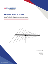
Horizontal and vertical polarizations can be achieved by rotating the
antenna from one mount to the other.
The Model 3161 Series Octave Bandwidth Pyramidal Horn Antenna is equipped
with a standard 1/4–20 mount. The mount is placed so as not to interfere with
incoming electromagnetic energy.
Once mounted, remove the red cover from the Type N connector and attach a
cable between the antenna and a transmitting/receiving RF device.
Mount to 4-TR
Model 3161 Series antennas mount directly to an ETS-Lindgren 4-TR Tripod; no
additional hardware is required. Secure the mount onto the 4-TR by tightening
the1/4–20 UNC mount knob.
Mounting Instructions | 19

Mount to 7-TR and Mast
Following is an option for mounting the Model 3161 Series onto an ETS-Lindgren
7-TR Tripod or mast. Contact the ETS-Lindgren Sales Department for
information on ordering optional mounting hardware.
Mast refers to 2070 Series, 2075, and 2175 Antenna Towers.
7-TR refers to 109042, 106328, and 108197 booms:
• 109042 boom—Straight boom; for general antenna mounting on a
7-TR
• 106328 boom—Offset boom; for general antenna mounting on a
7-TR with pneumatic or manual polarization
• 108197 boom—Center rotate boom; for rear-mount stinger-type
antennas only
20 | Mounting Instructions
/