Page is loading ...

Sample Draw Oxygen Monitor System (OMS)
User Manual
399374 Rev DMay, 2020


3
ETS-Lindgren Inc. reserves the right to make changes to any products herein to improve functioning or design.
Although the information in this document has been carefully reviewed and is believed to be reliable, ETS-Lindgren
does not assume any liability arising out of the application or use of any product or circuit described herein; nor does
it convey any license under its patent rights nor the rights of others. All trademarks are the property of their respective
owners.
© Copyright 2020 by ETS-Lindgren Inc. All Rights Reserved. No part of this document may be copied by any
means without written permission from ETS-Lindgren Inc.
Trademarks used in this document: The ETS-Lindgren logo and OMS are trademarks of ETS-Lindgren Inc.; NEMA is a
registered trademark of NEMA; 3M and Scotch-Brite are trademarks of 3M.
Revision Record
MANUAL, OXYGEN DEFICIENCY MONITOR | Part # 399374 Rev D
Revision Description Date
A Initial Release August, 2013
B Updated Introduction; added
installation location information;
added Sample Draw Sensor Tubing
December, 2013
C Updated remote display alarm
indicator information
February, 2017
D Updated warranty May, 2020

4

5
TABLE OF CONTENTS
NOTES, CAUTIONS AND WARNINGS 8
INTRODUCTION 9
Technology . . . . . . . . . . . . . . . . . . . . . . . . . . . . . . . . . . 9
Long-Life Zirconium Oxide Sensor Cell . . . . . . . . . . . . . . . . . . . . . . 9
Smart Electronics . . . . . . . . . . . . . . . . . . . . . . . . . . . . . . 9
Standard Conguration . . . . . . . . . . . . . . . . . . . . . . . . . . . . . 9
Other Optional Items . . . . . . . . . . . . . . . . . . . . . . . . . . . . . 10
ETS-Lindgren Product Information Bulletin . . . . . . . . . . . . . . . . . . . . 10
Optional Remote Display . . . . . . . . . . . . . . . . . . . . . . . . . . . 10
MAINTENANCE 11
Recommended Routine Maintenance . . . . . . . . . . . . . . . . . . . . . . 11
Every 6-12 Months . . . . . . . . . . . . . . . . . . . . . . . . . . . . . 11
Annually . . . . . . . . . . . . . . . . . . . . . . . . . . . . . . . . . 11
Replacement and Optional Parts . . . . . . . . . . . . . . . . . . . . . . . . 12
Service Procedures . . . . . . . . . . . . . . . . . . . . . . . . . . . . . 12
SPECIFICATIONS 13
Electrical Specications . . . . . . . . . . . . . . . . . . . . . . . . . . . . 13
Physical Specications . . . . . . . . . . . . . . . . . . . . . . . . . . . . 13
Performance Specications . . . . . . . . . . . . . . . . . . . . . . . . . . 13
Gas Detection System Specications. . . . . . . . . . . . . . . . . . . . . . . 13
Signal Outputs . . . . . . . . . . . . . . . . . . . . . . . . . . . . . . . 14
Default Factory Settings . . . . . . . . . . . . . . . . . . . . . . . . . . . . 14
COMPONENT VIEWS 17
Front View Exterior . . . . . . . . . . . . . . . . . . . . . . . . . . . . . . 17
Front View, Cover Removed . . . . . . . . . . . . . . . . . . . . . . . . . . 18
Transmitter Interior . . . . . . . . . . . . . . . . . . . . . . . . . . . . . . 19
Alarm Relay Board . . . . . . . . . . . . . . . . . . . . . . . . . . . . . . 19
BEFORE YOU BEGIN INSTALLATION 21
Site Requirements . . . . . . . . . . . . . . . . . . . . . . . . . . . . . . 21
Connect to 24 VDC Regulated Power . . . . . . . . . . . . . . . . . . . . . . 21
Connect OMS and Sensor Before Powering . . . . . . . . . . . . . . . . . . . . 21
Do Not Exchange the Sensor Electronics . . . . . . . . . . . . . . . . . . . . . 22
Use Proper Calibration Steps . . . . . . . . . . . . . . . . . . . . . . . . . . 22

6
Keep Away from Silicone Compounds . . . . . . . . . . . . . . . . . . . . . . . . . . . . . . 22
Keep Away from High Air Flow . . . . . . . . . . . . . . . . . . . . . . . . . . . . . . . . . 22
Keep Away From a Water Stream . . . . . . . . . . . . . . . . . . . . . . . . . . . . . . . . 22
INSTALLATION 23
Mounting the OMS . . . . . . . . . . . . . . . . . . . . . . . . . . . . . . . . . . . . . . 23
Transmitter and Sensor . . . . . . . . . . . . . . . . . . . . . . . . . . . . . . . . . . . 23
Enclosure Mounting Feet . . . . . . . . . . . . . . . . . . . . . . . . . . . . . . . . . . 24
Dust Filter . . . . . . . . . . . . . . . . . . . . . . . . . . . . . . . . . . . . . . . . 24
Sample Draw Sensor Tubing . . . . . . . . . . . . . . . . . . . . . . . . . . . . . . . . . . 25
Using an Available Waveguide . . . . . . . . . . . . . . . . . . . . . . . . . . . . . . . . 25
Using Kit 55160 to Install Waveguide . . . . . . . . . . . . . . . . . . . . . . . . . . . . . . 26
Wiring . . . . . . . . . . . . . . . . . . . . . . . . . . . . . . . . . . . . . . . . . . . 27
Connecting a Remote Horn and Strobe to OMS . . . . . . . . . . . . . . . . . . . . . . . . . . 28
Connecting a Remote Fan Contactor to OMS . . . . . . . . . . . . . . . . . . . . . . . . . . . 29
Initial Startup . . . . . . . . . . . . . . . . . . . . . . . . . . . . . . . . . . . . . . . . 30
OPERATION 31
Joystick Operation . . . . . . . . . . . . . . . . . . . . . . . . . . . . . . . . . . . . . . 31
Main Operation Mode . . . . . . . . . . . . . . . . . . . . . . . . . . . . . . . . . . . . . 31
Internal Sample Flow Rate . . . . . . . . . . . . . . . . . . . . . . . . . . . . . . . . . . . 32
Signal Outputs . . . . . . . . . . . . . . . . . . . . . . . . . . . . . . . . . . . . . . . 32
Instrument Faults . . . . . . . . . . . . . . . . . . . . . . . . . . . . . . . . . . . . . . 32
Loss of Power Indicator . . . . . . . . . . . . . . . . . . . . . . . . . . . . . . . . . . . . 33
Alarm Reset . . . . . . . . . . . . . . . . . . . . . . . . . . . . . . . . . . . . . . . . 33
PROGRAMMING THE OMS 35
Program Flowchart . . . . . . . . . . . . . . . . . . . . . . . . . . . . . . . . . . . . . . 35
Passwords . . . . . . . . . . . . . . . . . . . . . . . . . . . . . . . . . . . . . . . . . 39
Enter Password . . . . . . . . . . . . . . . . . . . . . . . . . . . . . . . . . . . . . . 39
Change Password . . . . . . . . . . . . . . . . . . . . . . . . . . . . . . . . . . . . . 40
Enable/Disable Password Function . . . . . . . . . . . . . . . . . . . . . . . . . . . . . . 41
Main Menus and Submenus . . . . . . . . . . . . . . . . . . . . . . . . . . . . . . . . . . 41
Set 4–20 mA Loop . . . . . . . . . . . . . . . . . . . . . . . . . . . . . . . . . . . . . 41
Set Formats . . . . . . . . . . . . . . . . . . . . . . . . . . . . . . . . . . . . . . . 42
Set Alarm Threshold Polarity . . . . . . . . . . . . . . . . . . . . . . . . . . . . . . . . . 42
Set Latching . . . . . . . . . . . . . . . . . . . . . . . . . . . . . . . . . . . . . . . 43
Reset Latching Alarm . . . . . . . . . . . . . . . . . . . . . . . . . . . . . . . . . . . . 44
Set Alarm Delay . . . . . . . . . . . . . . . . . . . . . . . . . . . . . . . . . . . . . . 44

7
Set Zero Suppression . . . . . . . . . . . . . . . . . . . . . . . . . . . . . . . . . . . . 44
Set Alarm Threshold . . . . . . . . . . . . . . . . . . . . . . . . . . . . . . . . . . . . 45
Set Alarm Hysteresis . . . . . . . . . . . . . . . . . . . . . . . . . . . . . . . . . . . . 46
Set Sensor Adjust . . . . . . . . . . . . . . . . . . . . . . . . . . . . . . . . . . . . . 46
SENSOR VERIFICATION 49
Required Gas and Equipment . . . . . . . . . . . . . . . . . . . . . . . . . . . . . . . . . 49
Sensor Verication Procedure . . . . . . . . . . . . . . . . . . . . . . . . . . . . . . . . . 50
Sensor Verication to Nitrogen . . . . . . . . . . . . . . . . . . . . . . . . . . . . . . . . . 50
Sensor Verication to Known Concentration of Oxygen . . . . . . . . . . . . . . . . . . . . . . . . 51
REMOTE DISPLAY ALARM INDICATOR 53
How to Mount the Remote Display Alarm Indicator . . . . . . . . . . . . . . . . . . . . . . . . . 53
How to Wire the Remote Display Alarm Indicator . . . . . . . . . . . . . . . . . . . . . . . . . . 54
Identication of Switches and Controls . . . . . . . . . . . . . . . . . . . . . . . . . . . . . . 55
How to Set up and Operate the Remote Display . . . . . . . . . . . . . . . . . . . . . . . . . . 56
How to Set the Zero and Full Scale Range . . . . . . . . . . . . . . . . . . . . . . . . . . . . 56
How to Set the Internal Alarms on the Remote Display . . . . . . . . . . . . . . . . . . . . . . . . 57
APPENDIX A: WARRANTY 59
Duration of Warranties for Oxygen Monitoring System . . . . . . . . . . . . . . . . . . . . . . . 59

8
NOTES, CAUTIONS AND WARNINGS
Note: Denotes helpful information intended to provide tips for better use of
the product.
Caution: Denotes a hazard. Failure to follow instructions could result in
minor personal injury and/or property damage. Included text gives proper
procedures.
Warning: Denotes a hazard. Failure to follow instructions could result in
SEVERE personal injury and/or property damage. Included text gives proper
procedures.
See the ETS-Lindgren Product Information Bulletin for safety, regulatory, and other product marking
information.
Refer to Manual: When product is marked with this symbol, see the
instruction manual for additional information. If the instruction manual has
been misplaced, download it from ets-lindgren.com, or contact ETS-Lindgren
Customer Service.
High Voltage: Indicates presence of hazardous voltage. Unsafe practice
could result in severe personal injury or death.
ONLY QUALIFIED PERSONNEL should operate or service this equipment.
CONTACT ETS-LINDGREN PRIOR TO SERVICING. Servicing (or
modifying) the unit by yourself may void your warranty.
WARRANTY

9
INTRODUCTION
The ETS-Lindgren Sample Draw Oxygen Monitoring System (OMS™) is a self contained oxygen deciency detection
system suitable for remote sampling of conned spaces; this single point monitor is designed for the continuous
detection and measurement of ambient oxygen concentration levels.
As a compact gas monitoring system, the OMS is ideal for the continuous monitoring of the air in MRI rooms, labs,
freezers, conned spaces, and other shielded enclosures where inert gases may displace the oxygen and create a
danger for patients and sta. The OMS is suitable for indoor and outdoor use, and is intended to be installed outside of
the shielded enclosure.
Each system consists of a long life zirconium oxide sensor cell and 3 wire transmitter. Unlike electrochemical sensor
cells, the zirconium oxide sensor cell provides stable oxygen readings even in areas where temperature and humidity
levels are changing. The OMS may be used as a standalone gas detector or connected to your own centralized control
and surveillance system.
Technology
Long-Life Zirconium Oxide Sensor Cell
The heart of the monitoring system is a zirconium sensor, which responds to low oxygen conditions within seconds
and provides accurate measurements over a wide temperature and humidity range. The zirconium sensor will operate
continuously for eight or more years, requiring minimum maintenance. There are no zero or span calibration pots to
adjust, and when compared to disposable sensors, the long life zirconium sensor can save hundreds of dollars in
annual maintenance.
Unlike concentration cells, the zirconium sensor does not need an oxygen reference gas for proper operation. The
OMS can detect low oxygen levels in conned spaces and process tools without the need of a reference gas.
Smart Electronics
The OMS incorporates a special electronic circuit that continuously monitors sensor operation. With the addition of
the alarm relay option, any cell degradation or complete failure will be detected immediately. This smart circuitry alerts
the user to sensor faults and other electrical problems that may interrupt surveillance through the standard mA signal
output signal or through the optional fault relay option.
Ideal for continuously monitoring oxygen levels in conned spaces or areas where inert gases are used, the OMS
does not drift or lose sensitivity with weather or temperature changes. The electronics are housed in a NEMA Type 4X
enclosure.
Standard Conguration
Note: The OMS must be installed outside of the shielded enclosure.
• Oxygen Monitoring System
• Power supply
• Dust lter

10
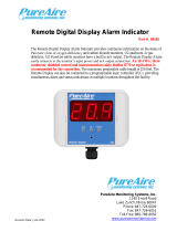
Optional Remote Display
The remote display receives oxygen concentration information from the
OMS. Up to two remote displays can be connected. See page 53 for
installation information.
Other Optional Items
• Remote Horn and Strobe
• Waveguide Installation Kit
ETS-Lindgren Product Information Bulletin
See the ETS-Lindgren Product Information Bulletin included with your shipment for the following:
• Warranty information
• Safety, regulatory, and other product marking information
• Steps to receive your shipment
• Steps to return a component for service
• ETS-Lindgren calibration service
• ETS-Lindgren contact information

11
MAINTENANCE
Calibrate or challenge the OMS ONLY outside the MRI suite.
Before performing any maintenance, follow the safety information in the
ETS-Lindgren Product Information Bulletin included with your shipment.
Maintenance of the OMS is limited to the procedures described in this
manual, and should be performed only by qualied personnel.
Warranty may be void if non-authorized procedures are performed, or if
performed by non-qualied personnel.
If you have any questions concerning maintenance, contact
ETS-Lindgren Customer Service.
WARRANTY
Recommended Routine Maintenance
The Sample Draw Oxygen Monitoring System (OMS™) is a continuous gas detection system that measures and
detects hazardous gas leaks in the workplace, and therefore requires periodic maintenance to ensure proper
operation. The frequency with which this routine maintenance is performed depends on your environment and
company policies. Following are recommendations intended as a general guideline.
Every 6-12 Months
• Visual checks: Check for power and proper operation. The OMS should output a 17.34 mA signal when the
oxygen level is at 20.9%. Also, the display should indicate 20.9% oxygen when the oxygen is at ambient levels.
• Sensor verication with nitrogen: The ambient oxygen level is 20.9%; therefore, under ambient conditions
verication of the OMS to 20.9% oxygen is constantly performed. The OMS requires periodic testing with nitrogen
only to verify the cell response to low oxygen levels. See Sensor Verication on page 49 for detailed steps.
Annually
Depending on the environment, the lter should be replaced every 12 months; in dusty environments, the lter may
need to be replaced more frequently. If the lter becomes completely blocked, the internal ow sensor will detect the
loss of ow and activate the fault relay and LED.

12
Replacement and Optional Parts
Note: ETS-Lindgren may substitute a similar part or new part number with
the same functionality for another part/part number. Contact ETS-Lindgren for
questions about part numbers and ordering parts.
Part Description Part Number
Optional Remote Display 255552
Filter Replacement 255551
Service Procedures
For the steps to return a system or system component to ETS-Lindgren for service, see the Product Information
Bulletin included with your shipment.

13
SPECIFICATIONS
Electrical Specications
A regulated 24 VDC power supply is required.
Power: 24 VDC external power
Consumption: Approximately 700 mA
Physical Specications
Height: 7.0 in (178 mm)
Width: 5.0 in (127 mm)
Depth: 5.0 in (127 mm)
Weight: 4.0 lb (2 kg)
Enclosure Type: NEMA Type 4X wall mount general purpose; not
intended for explosive atmospheres or electrically
classied areas
Performance Specications
Sensor Type: Long life zirconium oxide sensor cell, 0%–25%
Response Time: Within 2 seconds of any change in oxygen
Fault Indicators: ± 2% of reading
Operating Temperature: • Loss of VDC power (analog signal drops to 0 mA)
• Sensor cell failure: fault relay activated
Humidity: 0% to 95% relative humidity (RH)
Contact ETS-Lindgren for sensors which can operate
in 100% condensing RH environments
Gas Detection System Specications
Type: Long life zirconium oxide sensor cell, 0%–25%
Sensor Life: 8 to10 years, under normal conditions
Transmitter: • Microprocessor electronics with built in 3 digit
backlit LCD display
• Joystick-operated menus

14
Signal Outputs
Local Display: Digital display calibrated for oxygen
Note: The range is stated on the serial number and can be accessed via the
joystick on the front panel. In the measurement mode push the joystick down
to scroll the gas and range on the display. Push the joystick down again to
stop the scrolling and re-display the gas.
Standard: Analog Output: DC 4-20mA
Optional: • Relay Output: Dual level user selectable alarm
relays and one fault relay
• Rated: 2 amps @ 30 VDC; 2 amps @ 240 VAC
Default Factory Settings
Note: The built in relay settings are user changeable; see Main Menus and
Submenus on page 41 for more information.
Menu Function / Description Factory Default
Set 4–20 mA loop
To set the OMS 4 mA (zero) and 20 mA (span)
to your PLC or distributive control system.
The mA output is set at the factory using
a calibrated Fluke meter.
Set Formats; LED and Alarm Relay State
To set the relays to energize (normal) or de-
energize (fail safe) when the alarm activates.
Note: The LED indicators on the front panel
are connected directly to the alarm relays.
Alarm 1 = Normal
Alarm 2 = Normal
Fault - Normal
Alarm Delay
To set the time to wait until the relay alarms
activate.
Alarm = 5 seconds
Zero Suppression
Note: This function is not enabled on the
OMS.
000 = 0.00%
Set Alarm Thresholds
To set the level to alarm.
Note: The Audio Alarm feature is optional.
Alarm 1 = 19.5 %
Alarm 2 = 18.0 %
Audio = 19.5%
Set Alarm Hysteresis
Use when utilizing the OMS for control or
valves and process; see page 46 for more
information.
Alarm 1 = 0.0 %
Alarm 2 = 0.0 %
Audio = 0.0 %

15
Menu Function / Description Factory Default
Sensor Adjustment
For use when dynamically gas calibrating the
OMS to a known span gas; see page 46 for
more information.
No factory default
Sensor Adjustment
Manage Passwords
To change the password from the factory
default to a new password.
Factory default is 557

16

17
COMPONENT VIEWS
Front View Exterior
1. Front cover—Removable, waterproof cover that protects the interior of the transmitter; fastened by four
captive screws.
2. Joystick—Used to select and adjust the built in menus. The OMS features dual level user selectable alarms.
3. Digital display—Displays the oxygen levels in percentage; the normal oxygen level on Earth is 20.9%.
4. Alarm relay LEDs—Three multi colored LED indicators, from left to right:
• Alarm 2—Red
• Alarm 1—Orange
• Fault—Yellow
5. Mounting feet (4)
6. Sample inlet—Permits the ow of oxygen to enter the sensor.
7. Cable strain relief—The sealed opening in the transmitter housing for connecting the input power, 4–20 mA
output, and relay wiring.
8. Sample exhaust—Permits the ow of oxygen to exit the enclosure.
9. Front cover fasteners (4)—Four captive screws attach the front window to the base unit.
10. Front panel fastening screws (2)

18
Front View, Cover Removed
1. Sample pump—Brings in a sample to the sensor. Flow rate is preset at the factory, and is continuously
protected with a built in ow sensor. For more information, see Instrument Faults on page 32.
2. Sensor assembly—A zirconium oxide sensor cell that detects and measures the level of oxygen. When
exposed to oxygen, the sensor outputs an electrical signal proportional to the actual concentration of oxygen.
3. Retaining screws for electronics panel (2)—These mount the display front panel and electronics to the
enclosure.
When unfastening the front panel electronics, apply upwards pressure on the
back of the front panel to release the captive screw.
Front view with electronics panel rotated

19
Transmitter Interior
The fuse is eld-replaceable.
The power analog output terminal block is a 5 pin terminal block where
the 24 VDC power and 4–20 mA analog output connections are made
Alarm Relay Board
For the relays, from left to right:
NC-C-NO

20
/