
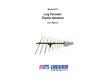
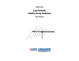
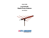
Model 3147
Log Periodic
Dipole Antenna
User Manual

ii |
ETS-Lindgren L.P. reserves the right to make changes to any product described
herein in order to improve function, design, or for any other reason. Nothing
contained herein shall constitute ETS-Lindgren L.P. assuming any liability
whatsoever arising out of the application or use of any product or circuit
described herein. ETS-Lindgren L.P. does not convey any license under its
patent rights or the rights of others.
© Copyright 1999–2020 by ETS-Lindgren L.P. All Rights Reserved. No part
of this document may be copied by any means without written permission
from ETS-Lindgren L.P.
Trademarks used in this document: The ETS-Lindgren logo is a trademark of
ETS-Lindgren L.P.
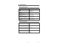
Revision Record
MANUAL 3147 LOG PERIODIC ANTENNA | Part #399160, Rev. G
Revision Description Date
A Initial Release January, 1999
B Updated content/branding October, 2002
C Edited content, rebranding changes June, 2008
D Updated photos April, 2009
E Added Mounting Instructions March, 2010
F Corrected error in Power
Requirements table; updated part
numbers in Mounting Instructions
November, 2010
G Updated calibration information April, 2020

| iii
Table of Contents
Notes, Cautions, and Warnings ................................................ v
1.0 Introduction .......................................................................... 7
Regarding Calibration of Log Periodic Dipole Antennas ................................ 8
ETS-Lindgren Product Information Bulletin ................................................... 8
2.0 Maintenance ....................................................................... 11
Maintenance Recommendations ................................................................. 11
Annual Calibration ....................................................................................... 11
Service Procedures ..................................................................................... 11
3.0 Specifications ..................................................................... 13
Electrical Specifications ............................................................................... 13
Physical Specifications ................................................................................ 13
4.0 Mounting Instructions ....................................................... 15
Using Included Mounting Adapters .............................................................. 15
Additional Mounting Options ........................................................................ 17
4-TR Mounting Options ................................................................................ 17
7-TR and Mast Mounting Options ................................................................ 18
2x2 Boom Mounting Options ....................................................................... 19
5.0 Operation ............................................................................ 21
Model 3147 Assembly Instructions .............................................................. 21
Model 3147 Use ........................................................................................... 21
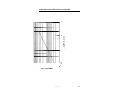
6.0 Typical Data ........................................................................ 23
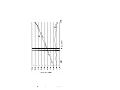
Typical VSWR for Model 3147 ..................................................................... 24
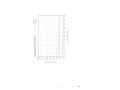
Typical Antenna Factor and Gain for Model 3147 ....................................... 25
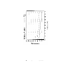
Beamwidth for Horizontally and Vertically Polarized Model 3147................ 28
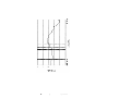
Front-to-Back Ratio for Model 3147 ............................................................. 31
Cable Attenuation (dB) at 20°C for 6-M Cable ............................................. 33
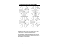
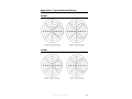
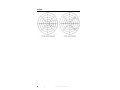
Typical Antenna Pattern for 200 MHz and 300 MHz ................................... 34
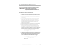
7.0 Radiated Emissions Measurement .................................. 35
Conversion Factors ...................................................................................... 36
8.0 Power Requirements ......................................................... 39
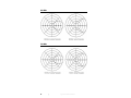
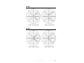
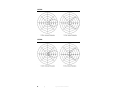
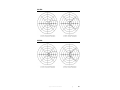
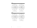
Appendix A: Typical Antenna Patterns ................................. 41

iv |
400 MHz ...................................................................................................... 41
500 MHz ...................................................................................................... 41
600 MHz ...................................................................................................... 42
700 MHz ...................................................................................................... 42
800 MHz ...................................................................................................... 43
900 MHz ...................................................................................................... 43
1.0 GHz ........................................................................................................ 44
1.5 GHz ........................................................................................................ 44
2.0 GHz ........................................................................................................ 45
2.5 GHz ........................................................................................................ 45
3.0 GHz ........................................................................................................ 46
3.5 GHz ........................................................................................................ 46
4.0 GHz ........................................................................................................ 47
4.5 GHz ........................................................................................................ 47
5.0 GHz ........................................................................................................ 48
Appendix B: Warranty ............................................................. 49

| v
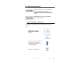
Notes, Cautions, and Warnings
Note: Denotes helpful information intended to
provide tips for better use of the product.
Caution: Denotes a hazard. Failure to follow
instructions could result in minor personal injury
and/or property damage. Included text gives proper
procedures.
Warning: Denotes a hazard. Failure to follow
instructions could result in SEVERE personal injury
and/or property damage. Included text gives proper
procedures.
See the ETS-Lindgren Product Information Bulletin for safety,
regulatory, and other product marking information.

vi |
This page intentionally left blank.

Introduction | 7
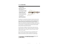
1.0 Introduction
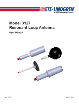
The ETS-Lindgren
Model 3147 Log Periodic
Dipole Antenna is a
linearly-polarized broadband
antenna designed to operate
over the frequency range of
200 MHz to 5 GHz. The
antenna was designed with
the latest revision to Part 15
of FCC Rules and
Regulations in mind. See
page 13 for specifications.
The Model 3147 is constructed from 30 elements mounted on two 6.35-mm by
12.7-mm booms. The choice of scaling factors, the various diameters of each
element, and the center-to-center spacing of the booms yield excellent VSWR
characteristics throughout the operating frequency range (see VSWR on
page 24). The precise design of the feed and the positioning of the elements on
the boom yield an optimum phase relationship. This causes the active region, at
any given frequency, to propagate RF energy towards the smaller elements,
leaving the elements behind it electrically dead.
The constant gain of the Model 3147 yields an antenna factor which varies
linearly with frequency, as shown in Typical Data on page 23. The variation is
smooth; therefore, accurate interpolation of performance between specified
frequency points is simple.
Due to the relatively high upper frequency limit, the small elements on the
Model 3147 are very thin. The antenna is equipped with an integral, low
dielectric-constant radome to protect the elements from possible damage.
Do not disassemble or drop the antenna or the
thin elements may be damaged.

8 | Introduction
Because the radome is almost RF-invisible, it has very little effect on the
performance of the Model 3147 (see VSWR on page 24).
The base of the Model 3147 accepts an ETS-Lindgren or other tripod mount with
1/4–20 threads. Additionally, the antenna is shipped with a support rod. A variety
of mounting options are available for the Model 3147. For information, see
Mounting Instructions on page 15.
Regarding Calibration of Log Periodic Dipole Antennas
The ETS-Lindgren Model 3147 antenna is calibrated based on ANSI C63.5 at a
distance of 10 m. Per the requirement of the standard, ETS-Lindgren measures
from the midpoint to the midpoint of the log periodic antennas.
Optionally the log periodic antenna can be calibrated per SAE ARP 958 (Society
of Automotive Engineers, Aerospace Recommended Practice). The SAR APR
958 requires an antenna spacing of one meter, measured from tip (front of the
antenna boom) to tip..
It is important in compliance demonstration testing to measure the
spacing from the antenna to the Equipment Under Test (EUT) as it
was measured when calibration was performed.
For additional information, contact ETS-Lindgren.
ETS-Lindgren Product Information Bulletin
See the ETS-Lindgren Product Information Bulletin included with your shipment
for the following:
Warranty information
Safety, regulatory, and other product marking information
Steps to receive your shipment
Steps to return a component for service
ETS-Lindgren calibration service
ETS-Lindgren contact information

Introduction | 9

10 | Introduction
This page intentionally left blank.

Maintenance | 11
2.0 Maintenance
Before performing any maintenance, follow the
safety information in the ETS-Lindgren
Product Information Bulletin included with your
shipment.
Maintenance of the Model 3147 Log Periodic Dipole Antenna is limited to
external components such as cables or connectors. If you have any questions
concerning maintenance, contact ETS-Lindgren Customer Service.
Maintenance Recommendations
If the Model 3147 is used outdoors, periodic removal of the antenna cable
connection and cleaning of any corrosion may be needed to maintain accuracy of
the measurements. An inspection to determine the need for cleaning should be
made at least every six months. More frequent inspection may be needed
depending on the atmosphere and the environment in which the antenna is used.
Annual Calibration
See the Product Information Bulletin included with your shipment for information
on ETS-Lindgren calibration services.
Service Procedures
For the steps to return a system or system component to ETS-Lindgren for
service, see the Product Information Bulletin included with your shipment.

12 | Maintenance
This page intentionally left blank.

Specifications | 13
3.0 Specifications
Electrical Specifications
Frequency Range: 200 MHz–5 GHz
VSWR: Average: 1.25:1
Maximum: 1.7:1
Impedance: 50 Ω
Maximum Continuous
Input Power:
80 W at 1 GHz
40 W at 5 GHz
Maximum Peak Input Power: 100 W at 1 GHz
50 W at 5 GHz
Connector: Precision N female
Physical Specifications
Height: 7.62 cm
3.0 in
Width: 88 cm
34.65 in
Depth: 97 cm
38.19 in
Weight: 4.25 kg
9.36 lb

14 | Specifications
This page intentionally left blank.

Mounting Instructions | 15
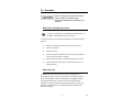
4.0 Mounting Instructions
Before connecting any components, follow the
safety information in the ETS-Lindgren
Product Information Bulletin included with your
shipment.
The Model 3147 is a precision measurement
device. Handle with care.
Using Included Mounting Adapters
The Model 3147 Log Periodic Dipole Antenna ships with these mounting
adapters:
100989 Polarizing Mounting
Adapter with 7/8–14 thread
receptacle
If you need to convert the polarizing
adapter to a 1/4–20 receptacle,
insert the 1/4–20 thread insert into
the polarizing adapter
105861 1/4–20 Thread Insert

16 | Mounting Instructions
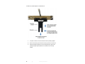
To attach the included adapters to the Model 3147:
1. If required, insert the 1/4–20 thread insert into the polarizing adapter.
2. Remove the mounting knob from the mounting bracket on the antenna.
3. Slide the polarizing adapter into the mounting bracket by placing the
polarizing adapter placed between the shoulders of the mounting
bracket.

Mounting Instructions | 17
4. Thread the mounting knob through the mounting bracket, then through
the polarizing adapter, and finally through the hex nut.
Do not cross thread or permanent damage to the adapter could occur.
5. Tighten the mounting knob to secure the antenna.
6. Attach the polarizing adapter and antenna to tripod or tower, as
required.
Additional Mounting Options
4-TR
M
OUNTING
O
PTIONS
Following are additional options for mounting the Model 3147 onto an
ETS-Lindgren 4-TR tripod. Contact the ETS-Lindgren Sales Department for
information on ordering optional mounting hardware.

18 | Mounting Instructions
7-TR
AND
M
AST
M
OUNTING
O
PTIONS
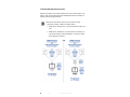
Following are options for mounting the Model 3147 onto an ETS-Lindgren 7-TR
Tripod or mast. Contact the ETS-Lindgren Sales Department for information on
ordering optional mounting hardware.
Mast refers to 2070 Series, 2075, and 2175 Antenna Towers.
7-TR refers to 109042, 108983, and 108507 booms:
109042 boom—Straight boom; for general antenna mounting on a
7-TR
108983 boom—Offset boom; for general antenna mounting on a
7-TR with pneumatic or manual polarization; can also be used to
mount stinger-type antennas

Mounting Instructions | 19
2
X
2 B
OOM
M
OUNTING
O
PTIONS
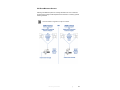
Following are additional options for mounting the Model 3147 onto a 2x2 boom.
Contact the ETS-Lindgren Sales Department for information on ordering optional
mounting hardware.
2x2 boom refers to a typical 2-inch by 2-inch boom.

20 | Mounting Instructions
This page intentionally left blank.
Page is loading ...
Page is loading ...
Page is loading ...
Page is loading ...
Page is loading ...
Page is loading ...
Page is loading ...
Page is loading ...
Page is loading ...
Page is loading ...
Page is loading ...
Page is loading ...
Page is loading ...
Page is loading ...
Page is loading ...
Page is loading ...
Page is loading ...
Page is loading ...
Page is loading ...
Page is loading ...
Page is loading ...
Page is loading ...
Page is loading ...
Page is loading ...
Page is loading ...
Page is loading ...
Page is loading ...
Page is loading ...
Page is loading ...
-
 1
1
-
 2
2
-
 3
3
-
 4
4
-
 5
5
-
 6
6
-
 7
7
-
 8
8
-
 9
9
-
 10
10
-
 11
11
-
 12
12
-
 13
13
-
 14
14
-
 15
15
-
 16
16
-
 17
17
-
 18
18
-
 19
19
-
 20
20
-
 21
21
-
 22
22
-
 23
23
-
 24
24
-
 25
25
-
 26
26
-
 27
27
-
 28
28
-
 29
29
-
 30
30
-
 31
31
-
 32
32
-
 33
33
-
 34
34
-
 35
35
-
 36
36
-
 37
37
-
 38
38
-
 39
39
-
 40
40
-
 41
41
-
 42
42
-
 43
43
-
 44
44
-
 45
45
-
 46
46
-
 47
47
-
 48
48
-
 49
49


ESCO Technologies ETS-Lindgren 3147 User manual
- Type
- User manual
- This manual is also suitable for
Ask a question and I''ll find the answer in the document
Finding information in a document is now easier with AI
Related papers


Other documents
-
West Penn Wire CN-FS11V Datasheet
-
 Antenna Experts LP-500-2500 Installation guide
-
 ETS-Lindgren 3144 Owner's manual
-
 ETS-Lindgren 3162-02 Owner's manual
-
 ETS-Lindgren 3161 Owner's manual
-
 ETS-Lindgren 3140b Owner's manual
-
 ETS-Lindgren 1052 Owner's manual
-
 ETS-Lindgren 3148B User manual
-
Magnavox MG-ANT-104 Owner's manual
-
Zebra ML-2499-HPA8-01 Datasheet


