Page is loading ...

1
Installations- und Betriebsanleitung
1/3” Tag/Nacht-Farbkamera mit IR-Schwenkfilter
VKC-1370, VKC-1370/12-24
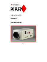
Installation and Operating Instructions
1/3” Day/Night Colour Camera with IR Cut Filter
VKC-1370, VKC-1370/12-24

3
Contents
1. Safety Instructions .............................................................................................................................................17
2. General Description ...........................................................................................................................................
18
3. Part Names .......................................................................................................................................................
19
3.1 Side view .................................................................................................................................................19
3.2 Rear view ................................................................................................................................................20
3.2.1 VKC-1370 (Art. No. 92537) .........................................................................................................20
3.2.2 VKC-1370/12-24 (Art. No. 92538) ...............................................................................................20
4. Description of External Controls .........................................................................................................................
21
4.1 VKC-1370 (Art. No. 92537) ......................................................................................................................21
4.2 VKC-1370/12-24 (Art. No. 92538) ............................................................................................................22
4.3 Potentiometer for Iris Level Control ..........................................................................................................24
5. Installation Instructions ......................................................................................................................................
24
5.1 VKC-1370 (Art. No. 92537) ......................................................................................................................24
5.2 VKC-1370/12-24 (Art. No. 92538) ............................................................................................................24
5.3 Power Supply Connections ......................................................................................................................25
5.3.1 VKC-1370 (Art. No. 92537) .........................................................................................................25
5.3.2 VKC-1370/12-24 (Art. No. 92538) ...............................................................................................25
5.4 Attaching the lens ....................................................................................................................................25
5.5 Setting the back focus lock ......................................................................................................................26
6. Specifications ....................................................................................................................................................28
7. Dimensional Drawings .......................................................................................................................................
30

17
1. Safety Instructions
• Read these safety instructions and the operation manual first before you install and commission the camera.
• Keep the manual in a safe place for later reference.
• Protect your camera from contamination with water and humidity to prevent it from permanent damage.
Never switch the camera on when it gets wet. Have it checked at an authorized service center in this case.
• Never operate the camera outside of the specifications as this may prevent the camera functioning.
• Do not operate the cameras beyond their specified temperature, humidity or power ratings.
Operate the camera only at a temperature range of -10°C to +50°C and at a humidity of max. 90%.
• To disconnect the power cord of the unit, pull it out by the plug. Never pull the cord itself.
• Pay attention when laying the connection cable and observe that the cable is not subject to heavy loads, kinks, or
damage and no moisture can get in.
• The warranty becomes void if repairs are undertaken by unauthorized persons. Do not open the camera housing.
• Never point the camera towards the sun with the aperture open. This can destroy the sensor.
• Installation, maintenance and repair have to be carried out only by authorized service centers.
Before opening the cover disconnect the unit from mains input.
• The fitter is responsible for the system of protection being followed in accordance with the technical data, e.g. by
sealing of the cable outlet with silicone.
• Contact your local dealer in case of malfunction.
• Only use original parts and original accessories from Videor E. Hartig GmbH.
• Do not use strong or abrasive detergents when cleaning the dome. Use a dry cloth to clean the dome surface.
In case the dirt is hard to remove, use a mild detergent and wipe gently.
• During assembly, care must be taken to ensure that existing seals are correctly inserted and are not
displaced as a result of assembly.
You must not continue to use damaged seals.
NOTE: This is a class A digital device. This digital device can cause harmful interference in a residential area;
in this case the user may be required to take appropriate corrective action at his/her own expense.

18
2. General Description
• 1/3” Super HAD Colour/B&W CCD Sensor
• Sensitivity: 0.04Lux at F1.2 (B&W)
(VKC-1370, Art. No. 92537)
0.05Lux at F1.2 (B&W)
(VKC-1370/12-24, Art. No. 92538)
• Automatic Gain Control (AGC)
• Removable IR Cut Filter
• Switchable Backlight Compensation (BLC)
• Iris/Shutter Control Selectable (ALC/ESC)
• Switchable Flickerless Adjustment
• Automatic White Balance (ATW)
• Enhanced Sharpness Compensation
• Auto-Iris and DC-Iris Control
(VKC-1370, Art. No. 92537)
DC-Iris Control
(VKC-1370/12-24, Art. No. 92538)
• Supply Voltage: 230VAC/50Hz
(VKC-1370, Art. No. 92537)
12VDC or 24VAC
(VKC-1370/12-24, Art. No. 92538)
• CS Mount
Supplied Items
• Day/night colour camera
• Power cord
(only VKC-1370, Art. No. 92537)
• Installation and Operating Instructions

19
3. Part Names
3.1 Side view
(1) Back focus adjustment
(2) Lens Connector for auto iris lenses
(3) Back focus adjustment lock screw
(4) Threaded camera mount
Lens Connectors for Auto-iris lens (AI & DC Drive)
Pin No. VIDEO Drive (only #92537) DC Drive
1 V+ Damp (-)
2 No Connect Damp (+)
3 Iris Signal Drive (+)
4 GND GND
Lens Switch VIDEO Position DC Position
1
2
4
3
2

20
3.2 Rear view
3.2.1 VKC-1370 (Art. No. 92537)
(a) Function switch (SW 1~4)
(b) DC/AI iris switch
(c) Lens connector for auto iris lenses
(d) DC Iris level control
3.2.2 VKC-1370/12-24 (Art. No. 92538)
Dip Switch
1. ALC/ESC
2. BLC On/Off
3. Flickerless On/Off
4. D/N On/Off
(e) Video output connector (BNC)
(f) Power inlet
(g) Power indicator LED
(a) Function switch (SW 1~8)
(b) Lens connector for auto iris lenses
(c) DC iris level control
(d) Video output connector (BNC)
Dip Switch
1. ALC/ESC
2. BLC On/Off
3. Flickerless On/Off
4. AGC Turbo On/Off
5. SHARP
6. D/N
7. IR MODE
8.
(e) Power indicator LED
(f) Power inlet
f
g
b
a
c
d
e
f
b
c
d
e
a

21
4 Description of External Controls
4.1 VKC-1370 (Art. No. 92537)
Dip Switch Description setting & key functions
No. Function Default ON OFF
1 ALC /ESC OFF ESC mode
Electronic shutter mode
ALC mode when an auto iris lens is
installed.
2 BLC OFF BLC ON
Back light compensation is enabled.
BLC OFF
Back lit compensation is disabled.
3 Flickerless OFF Flickerless mode is enabled. Flickerless mode is disabled.
4 Day / Night ON Day-Night mode is enabled. Firmly connected to colour mode
SW 1. ALC / ESC (Default: OFF)
Used to select iris control mode. When set to ESC, camera operates in electronic shutter control (ESC) mode and can
be installed with the manual or fixed iris lens. ESC mode is the most economic solution but may have some following
disadvantages comparative to ALC mode at auto iris lens:
• More smear and less clear image when shooting the very bright object.
• Colour rolling or video level hunting may occur under the florescent light when the camera operates in ESC and INT
modes (NTSC version only).
When set to ALC, camera operates in auto iris lens control mode and should be installed with either type of the auto
iris lenses (Video-drive type or DC-drive). Auto iris lens is used for best quality video.
SW 2. BLC (Backlight compensation) ON/OFF (Default: OFF)
If the subject you wish to view is too dim because of a bright background, set the BLC switch to ON to compensate for
the bright background. With BLC on, the background brightness may saturate in some cases. This function may not
operate properly if the object is too small compared to the area of the background. This function can be used with the
linear shutter (EE or ESC) and be OFF with auto iris lens (Al lens or ALC mode).
SW 3. Flickerless ON/OFF (Default: OFF)
Flickerless mode is useful in areas where AC mains is 50Hz and TV system is NTSC such like Japan or AC is 60Hz
and TV system is PAL to reduce the flicker under the florescent light. Where FL is set to ON, the low light sensitivity is
down about 30%.
SW 4. Day-Night (ICR) ON/OFF (Default: ON)
DAY-NIGHT ON/OFF SW enables or disables the day-night mode. If set to ON, day-night mode is enabled and camera
determines to enter / exit NIGHT mode from / to DAY mode automatically according to the scene illumination. When
the scene illumination is getting darker than a half video level, camera changes its mode to NIGHT and removes its
optical filter to get a higher video level and switches to B/W mode.

22
In NIGHT mode, camera provides the real time B/W video and can accept the IR light. When the illumination is getting
brighter, camera returns to DAY mode and returns its optical filter and switches to colour mode.
If set to OFF, camera operates just like a normal camera and does not perform NIGHT mode..
4.2 VKC-1370/12-24 (Art. No. 92538)
Dip Switch Description setting & key functions
No. Function Default ON OFF
1 ALC /ESC OFF ESC mode
Electronic shutter mode
ALC mode when an auto iris lens is
installed.
2 BLC OFF BLC ON
Back light compensation is enabled.
BLC OFF
Back lit compensation is disabled.
3 Flickerless OFF Flickerless mode is enabled. Flickerless mode is disabled.
4 AGC Turbo OFF AGC Turbo ON Normal AGC gain
5 Sharpness ON Sharpness enhancement is enabled. Sharpness enhancement is disabled.
6 Day / Night ON Day-Night mode is enabled. Firmly connected to colour mode
7 IR mode OFF The mode „Switch over delay of the
IR filter” is enabled and reduces a
possible switch from DAY to NIGHT or
reverse at a certain condition.
„Switch over delay of the IR filter”
mode OFF
Set to OFF when NO iteration is
expected.
8 N/A OFF Reserved for future use
SW 1. ALC / ESC (Default: ALC)
Used to select iris control mode. When set to ESC, camera operates in electronic shutter control (ESC) mode and can
be installed with the manual or fixed iris lens. ESC mode is the most economic solution but may have some following
disadvantages comparative to ALC mode at auto iris lens:
• More smear and less clear image when shooting the very bright object.
• Colour rolling or video level hunting may occur under the florescent light when the camera operates in ESC and INT
modes (NTSC version only).
When set to ALC, camera operates in auto iris lens control mode and should be installed with either type of the auto
iris lenses (Video-drive type or DC-drive). Auto iris lens is used for best quality video.
SW 2. BLC (Backlight compensation) ON/OFF (Default: OFF)
If the subject you wish to view is too dim because of a bright background, set the BLC switch to ON to compensate for
the bright background. With BLC on, the background brightness may saturate in some cases. This function may not
operate properly if the object is too small compared to the area of the background. This function can be used with the
linear shutter (EE or ESC) and be OFF with auto iris lens (Al lens or ALC mode).

23
SW 3. Flickerless ON/OFF (Default: ON)
Flickerless mode is useful in areas where AC mains is 50Hz and TV system is NTSC such like Japan or AC is 60Hz
and TV system is PAL to reduce the flicker under the florescent light. Where FL is set to ON, the low light sensitivity is
down about 30%.
SW 4. AGC Turbo ON/ OFF (Default: OFF)
AGC is Automatic Gain Control
SW 5. Sharpness ON/OFF (Default: ON)
SW 6. Day-Night (ICR) ON/OFF (Default: ON)
DAY-NIGHT ON/OFF SW enables or disables the day-night mode. If set to ON, day-night mode is enabled and camera
determines to enter / exit NIGHT mode from / to DAY mode automatically according to the scene illumination. When
the scene illumination is getting darker than a half video level, camera changes its mode to NIGHT and removes its
optical filter to get a higher video level and switches to B/W mode.
In NIGHT mode, camera provides the real time B/W video and can accept the IR light. When the illumination is getting
brighter, camera returns to DAY mode and returns its optical filter and switches to Colour mode.
If set to OFF, camera operates just like a normal camera and does not perform NIGHT mode.
SW 7 IR mode ON/OFF (Default: OFF)
Used to reduce a possibility from Day to Night or reverse under a certain scene illumination. This mode was derived
from simple IR Cut filter mechanism which is switched from day to night or night to day based on scene illumination.
A typical IR cut filter type D&N camera could be switched from Colour to BW or reverse under specific scene illumi
-
nation values, but sometimes iterations (switch frequency) occur when switching from/to (Night <--> Day) under
specific external IR light source. IR mode can give a little margin of the IR iteration at specific condition by increasing
the threshold value (Night to Day) adjustment.
IR mode is enabled, it reduces iteration of the filter switch (repeated IN-and-OUT) during varying lighting conditions.
In IR mode, the Night to Day threshold will be around 6.0Lux and around 4.0Lux when off. The Lux is affected by
scene illumination, but has a limit to reduce IR switch frequency under stronger external IR light.
SW 8. N/A (Reserved for future usage)

24
5. Installation Instructions
5.1 VKC-1370 (Art. No. 92537)
• Make sure the power is removed before the installation.
• Follow the order for applying power.
Connect the AC power cord. This power cord accepts 220-240V~50Hz +/-1Hz.
5.2 VKC-1370/12-24 (Art. No. 92538)
• Make sure the power is removed before the installation.
• Follow the order for applying power.
First connect the low voltage (12VDC or 24VAC), then plug the AC adapter to AC outlets to avoid an improper reset
from power jitter and a damage from the surge voltage when no load.
4.3 Potentiometer for Iris Level Control
Used to set the video level by adjusting the iris of the connected DC drive auto iris lens.
The Excellent lens control characteristic makes it very precise, very stable, and very easy to adjust the video level.
Monitor screen LEVEL control direction
To increase the brightness clockwise
To decrease the brightness
counterclockwise
IRIS

25
5.3 Power Supply Connections
5.3.1 VKC-1370 (Art. No. 92537)
This camera can work in 230VAC voltage power. Primary and secondary grounds are completely isolated to remove
the possible ground-loop problems.
Use power cord supplied 1.5m.
5.3.2 VKC-1370/12-24 (Art. No. 92538)
Camera can work with either 12VDC or 24VAC. It does NOT require the polarity-matched connection for 12VDC supply.
Primary and secondary grounds are completely isolated to avoid the possible ground-loop problems. Its excellently
wide operating voltage range of 10V-30V for DC and 15-29V for AC gives an extra flexibility at the installation.
5.4 Attaching the Lens
• Remove the Dust Protection cap from the lens mount
• Screw the lens onto the camera without using force
CLASS 2
24VAC
12VDC

26
5.5 Setting the Back Focus Lock
The back focus is the distance between the lens support on the camera and the image sensor. Optimum focus is
only possible when the correct distance is set. It may be necessary to set the back focus in individual cases due
to production tolerances of the lens. The iris of the lens must be open as wide as possible. (smallest F value) to set
the back focus. For lenses with automatic iris control, you will require a ND filter (gray filter) to prevent the iris from
closing in bright light.
L
M
AL
K
M
L
C mount lens
CS mount lens
Adjustment of flange
focus for fixed focus
lenses
This adjustment (distance between lens casing and sensor surface) is required if a
sharp definition cannot be obtained with the lens focussing, or in order to adjust the
position.
To obtain a sharp definition, point the camera at an object which is at least 2000 times
further away from the front of the lens than the focal length. (If the focal length is
7.5mm, the object must be at least 15m distant from the camera).
Open the aperture fully and set the focus to
(infinite).
If the lens has automatic exposure control, select a dark object, or better use an ND
filter (64-x) to ensure that the aperture is fully open.
Undo set screw
M. Turn the lens with the CS mount connection until the definition is
sharp. When finished, retighten screw M.
CS mount
L for CS mount lenses. Insert a C mount-Ring K if C mount lenses are used.
Adjustment of flange
focus for variable focus
lenses
To obtain a sharp definition, point the camera at an object which is at least 5 times the
minimum lens distance (MOD) of the lens. (If this is 1m, the object must be at least 5m
distant from the camera).
Open the iris fully and set the lens to the maximum tele position and focus with the
focus ring.
If the lens has automatic iris control, select a dark object (or use an ND filter, 64-x) to
ensure that the iris is fully open.
Set the lens to the maximum wide-angle position.
Undo set screw
M and turn the CS ring on the camera until an optimal sharpness is
reached. Repeat the process for checking purposes, if necessary.
When finished, retighten screw
M.
Note
The value stated in the diagram as AL (depth of thread of the lens with CS mount: <-
5mm) must be observed. The camera may be damaged if this value is exceeded. When
installing a lens with CS mount, never use a C mount adapter ring.

27
Explanation of terms for iris setting
AGC (automatic gain
control)
This starts tooperate when the light intensity is insufficient to deliver a full video signal
(1Vp-p). The greater the gain, the greater the signal noise in the picture. It is generally
activated between 0.8 and 1.0Vp-p.
White clip
Signal limitation at high image amplitudes. The white clip value generally lies between
1.1 and 1.2 Vp-p.
ESC (automatic
shutter control)
This automatically controls the shutter times, it starts when the light intensity becomes
stronger and the signal would otherwise be limited/over-regulated by the white clip
feature. Automatic shutter control is mainly applied for manual lenses.
If a camera is operated with controlled lenses, regardless of whether DC or AI, the ESC
must be switched off (DIP switch 1 to „ALC”). Problems arise if this is not done because
both control systems try to steer the volume of light for the camera. As the ESC generally
reacts faster, the iris remains fully opened and the shutter resumes the control work,
which produces major drawbacks. As the iris is open, the depth of focus is very low. When
shutter times are short, this can cause a smear effect (bright, vertical stripes in light parts
of the picture).
Iris adjustment
The working point of the iris should always be above the AGC start and below that of the
white clip. This range is very small with some cameras, making it difficult to adjust the
lens. It is therefore advisable to switch off the AGC (if possible) when adjusting the iris.
Once the lens has been focussed, the AGC must be switched back on (only for cameras
which allow the AGC to be switched off).
In the case of DC lenses, the working point of the iris is adjusted at the camera’s level
potentiometer (the AI amplifier is built into the camera).
In the case of AI lenses, the level potentiometer is located on the lens (the AI amplifier is
built into the lens).
IR cut filter
Important note on
the IR cut filter
If an IR light source is used for illumination and if this exceeds a certain brightness, the
filter is panned in. The brightness can then no longer be sufficient and the filter is panned
out. This can lead to the filter being constantly panned in and out (with a time delay) in a
special configuration. This can be prevented by:
a) reducing the light level
b) toning down reflectors
c) changing the image
Addition when using
cameras for day/night
application
Even if the lens is a day/night lens with stabilised focus regulation (0-focus shift), a
minor flange focus is possible between visible light and IR light.
If there is a day/night application with IR illumination, the flange focus should be set
under IR light conditions. This is because the iris is generally opened when used at
night due to the poor level of light and low depth of focus. During the day, the iris is
continuously closed further, there is a greater depth of focus and the difference in the
flange focus is compensated.

28
6. Specifications
Type VKC-1370 VKC-1370/12-24
Art. No. 92537 92538
System
Day&night
Video standard
PAL
Sensor size
1/3”
Imager
Sony Super HAD II Interline Transfer
Active picture elements
440,000 (H) 752 x (V) 582 pixels
Signal processing
Digital (DSP)
Synchronization
Internal
Signal-to-noise ratio
50dB (AGC OFF)
Horizontal resolution
540 TVL
Sensitivity (at 50% video signal)
0.14Lux (colour), 0.04Lux at b&w
(Videor measurement result at F1.2)
0.16Lux (colour), 0.05Lux at b&w
(Videor measurement result at F1.2)
High-speed shutter (ESC)
1/50 ~1/100,000sec.
Integration rate
no
Digital Noise Reduction (DNR)
no
Automatic gain control (AGC)
28dB max.
Backlight compensation
BLC, ON/OFF switchable
White balance
Automatic and manual (ATW/AWB)
White balance (ATW)
2000K ~8000K
Aperture Correction (APC)
Horizontal and vertical
Flickerless function
Supplied
IR cut filter
Switchable
Day/Night switching
Automatic and manual
Lens mount
CS
Usable iris controls
Manual iris, DC/AI controlled iris
External adjustments
4 DIP switches for: ALC/ESC, BLC
On/Off, Flickerless On/Off, Day/Night,
Lens select (AI/DC iris control). Level
for DC voltage controlled iris, Flange
focus
8 DIP switches for: ALC/ESC, BLC
On/Off, Flickerless On/Off, Turbo AGC
On/Off, Sharpnes On/Off, Day/Night,
IR mode On/Off. Level for DC voltage
controlled iris, Flange focus
Video outputs (type)
CVBS
Video output
1 Vp-p, (C)VBS, 75 ohms, BNC
External connections
Video (BNC), Auto/DC Iris (4-pin), Power input (3-pin)
Serial interfaces
no
Camera mount
1/4”- 20 UNC thread on top and bottom

29
Optional Accessories
Art. No. Type Description
70536 VT-PS12DC-9
Plug-in Power Supply Unit 100~240VAC/12VDC, 1A, regulated, with open ends
70495 VT-PS12DC-7
Plugable PSU with Continent & UK mains plug-ins, 100-240V/12VDC-1.25A,
regulated, with open ends
77773 VT-PS12DCDT1
Power Supply Unit 12VDC/1,0A, regulated, desktop version, 1.8m DC-cable each
with open ends
43106 C/CS RING-AL
Adapter ring C/CS mount, aluminium anodized
Type VKC-1370 VKC-1370/12-24
Art. No. 92537 92538
Housing
Metal
Protection rating
IP40
Hidden cable management
no
Supply voltage
230VAC 12VDC, 24VAC,
10 ~30VDC, 15 ~29VAC
Power consumption
50mA max.
3.0watts
Temperature range (Operation)
-10° ~+50°C
Dimensions
See drawing
Colour
Pantone Cool Gray 2C
Weight
410g 275g
Parts supplied
Camera, Manual, Power cord Camera, Manual
Certificates
CE
/