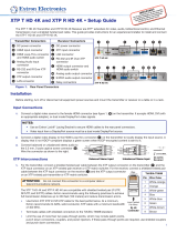
3
Input connectors
Input boards for local sources may include the following connectors:
• HDMI input connectors — Connect a digital video source to a female HDMI input connector. It can accept HDMI, DVI (with
an appropriate adapter), or dual mode DisplayPort video signals.
NOTE: Use an Extron LockIt
®
Lacing Bracket to secure HDMI cables to the rear panel connectors.
• DVI input connectors — Connect a digital video source to a female DVI input connector.
• SDI input and Loop Out connectors — Connect a 3G-SDI, HD-SDI, or SDI video source to a BNC input connector. For each
input, connect an optional digital display for local output of the source on the corresponding BNC Loop Out connector.
NOTE: Use 75 ohm terminators on unused Loop Out connectors.
• VGA input connectors — Connect an analog RGB video source to a female 15-pin HD VGA connector.
• Analog audio input connectors — Connect
balanced or unbalanced stereo audio to a 3.5 mm,
5-pole captive screw connector. Wire the connector
as shown to the right.
Output connectors
Output boards for local output devices may include the following connectors:
• HDMI output connectors — Connect a digital video display to a female HDMI output connector.
NOTE: Use an Extron LockIt
®
Lacing Bracket to secure HDMI cables to the rear panel connectors.
• DVI output connectors — Connect a digital video display to a female DVI output connector.
• Analog audio output connectors — Connect
a balanced or unbalanced, stereo or mono
audio device to a 3.5 mm, 5-pole captive screw
connector for 2-channel stereo analog audio.
Wire the connector as shown to the right.
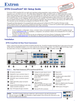
Connection Details
Twisted pair recommendations for XTP communication
ATTENTION: Do not connect this connector to a computer data or telecommunications network.
The twisted pair input and output boards are compatible with shielded twisted pair (F/UTP, SF/UTP, and S/FTP) cable. Extron
recommends using the following practices to achieve full transmission distances up to 330 feet (100 meters) and reduce
transmission errors.
• Use Extron XTP DTP 24 SF/UTP cable for the best performance. At a minimum, Extron recommends 24 AWG, solid
conductor, STP cable with a minimum bandwidth of 400 MHz.
• Terminate cables with shielded connectors to the TIA/EIA-T568B standard.
• Limit the use of more than two pass-through points, which may include patch points,
punch down connectors, couplers, and power injectors. If these pass-through points are
required, use shielded couplers and punch down connectors.
NOTE: When using shielded twisted pair cable in bundles or conduits, consider the
following:
• Do not exceed 40% ll capacity in conduits.
• Do not comb the cable for the rst 20 meters, where cables are straightened, aligned,
and secured in tight bundles.
• Loosely place cables and limit the use of tie wraps or hook-and-loop fasteners.
• Separate twisted pair cables from AC power cables.
Do not tin
Unbalanced Stereo InputBalanced Stereo Input
Tip
Ring
Tip
Ring
ves
Tip
Sleeve
Sleeve
Tip
LR
LR
Do not tin
the wires!
Tip
Ring
Tip
Ring
ves
Tip
No Ground Here
Tip
Sleeves
LR
LR
TIA/EIA-T568B
Pin Wire Color
1
White-orange
2
Orange
3
White-green
4
Blue
5
White-blue
6
Green
7
White-brown
8
Brown
12345678
RJ-45
Connector
Insert Twisted
Pair Wires
Pins: