Page is loading ...

H3C MSR3610-I-DP[IE-DP]
ICT Converged Gateway Installation Guide
New H3C Technologies Co., Ltd.
http://www.h3c.com
Document version: 6W102-20190108

Copyright © 2018-2019, New H3C Technologies Co., Ltd. and its licensors
All rights reserved
No part of this manual may be reproduced or transmitted in any form or by any means without prior written
consent of New H3C Technologies Co., Ltd.
Trademarks
Except for the trademarks of New H3C Technologies Co., Ltd., any trademarks that may be mentioned in this
document are the property of their respective owners.
Notice
The information in this document is subject to change without notice. All contents in this document, including
statements, information, and recommendations, are believed to be accurate, but they are presented without
warranty of any kind, express or implied. H3C shall not be liable for technical or editorial errors or omissions
contained herein.
Environmental protection
This product has been designed to comply with the environmental protection requirements. The storage, use,
and disposal of this product must meet the applicable national laws and regulations.

Preface
This installation guide describes the installation procedure for the H3C MSR3610-I-DP [IE-DP] ICT
converged gateway. It covers installation preparation, device installation, hardware replacement,
and troubleshooting.
This preface includes the following topics about the documentation:
• Audience.
• Conventions.
• Documentation feedback.
Audience
This documentation is intended for:
• Network planners.
• Field technical support and servicing engineers.
• Network administrators working with the routers.
Conventions
The following information describes the conventions used in the documentation.
Command conventions
Convention Description
Boldface Bold
text represents commands and keywords that you enter literally as shown.
Italic
Italic text represents arguments that you replace with actual values.
[ ] Square brackets enclose syntax choices (keywords or arguments) that are optional.
{ x | y | ... }
Braces enclose a set of required syntax choices separated by vertical bars, from which
you select one.
[ x | y | ... ]
Square brackets enclose a set of optional syntax choices separated by vertical bars,
from which you select one or none.
{ x | y | ... } *
Asterisk marked braces enclose a set of required syntax choices separated by vertical
bars, from which you select a minimum of one.
[ x | y | ... ] *
Asterisk marked square brackets enclose optional syntax choices separated by vertical
bars, from which you select one choice, multiple choices, or none.
&<1-n>
The argument or keyword and argument combination before the ampersand (&) sign
can be entered 1 to n times.
# A line that starts with a pound (#) sign is comments.
GUI conventions
Convention Description
Boldface
Window names, button names, field names, and menu items are in Boldface. For
example, the
New User
window opens; click
OK
.
> Multi-level menus are separated by angle brackets. For example,
File
>
Create
>
Folder
.

Symbols
Convention Description
WARNING!
An alert that calls attention to important information that if not understood or followed
can result in personal injury.
CAUTION:
An alert that calls attention to important information that if not understood or followed
can result in data loss, data corruption, or damage to hardware or software.
IMPORTANT:
An alert that calls attention to essential information.
NOTE:
An alert that contains additional or supplementary information.
TIP:
An alert that provides helpful information.
Network topology icons
Convention Description
Represents a generic network device, such as a router, switch, or firewall.
Represents a routing-capable device, such as a router or Layer 3 switch.
Represents a generic switch, such as a Layer 2 or Layer 3 switch, or a router that
supports Layer 2 forwarding and other Layer 2 features.
Represents an access controller, a unified wired-WLAN module, or the access
controller engine on a unified wired-WLAN switch.
Represents an access point.
Represents a wireless terminator unit.
Represents a wireless terminator.
Represents a mesh access point.
Represents omnidirectional signals.
Represents directional signals.
Represents a security product, such as a firewall, UTM, multiservice security
gateway, or load balancing device.
Represents a security module, such as a firewall, load balancing, NetStream, SSL
VPN, IPS, or ACG module.
Examples provided in this document
Examples in this document might use devices that differ from your device in hardware model,
configuration, or software version. It is normal that the port numbers, sample output, screenshots,
and other information in the examples differ from what you have on your device.
T
T
T
T

Documentation feedback
You can e-mail your comments about product documentation to [email protected].
We appreciate your comments.

i
Contents
Preparing for installation ···································································· 1
Safety recommendations ············································································································· 1
Safety symbols ··················································································································· 1
General safety recommendations ··························································································· 1
Electricity safety ·················································································································· 1
Laser safety ······················································································································· 1
Examining the installation site ······································································································· 2
Temperature and humidity ····································································································· 2
Cleanliness ························································································································ 2
Cooling ····························································································································· 3
ESD prevention ··················································································································· 3
EMI ·································································································································· 4
Lightning protection ············································································································· 4
Rack requirements ·············································································································· 4
Installation tools and accessories ·································································································· 5
Pre-installation checklist ·············································································································· 6
Installing the device ·········································································· 8
Installation prerequisites ·············································································································· 8
Installation flowchart ··················································································································· 8
Mounting the device on a workbench ····························································································· 9
Mounting the device in a rack ····································································································· 11
Device dimensions and rack requirements ·············································································· 11
Installing the device in a rack ······························································································· 12
Connecting the grounding cable ·································································································· 13
Installing a SIC interface module ································································································· 14
Connecting interface cables ······································································································· 14
Connecting an Ethernet copper port ······················································································ 14
Connecting an Ethernet fiber port ························································································· 15
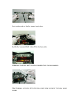
Installing a hard disk ················································································································· 16
Connecting the console cable and setting terminal parameters ·························································· 17
Connecting the console cable ······························································································ 17
Setting configuration terminal parameters ··············································································· 17
Connecting an AC power cord ···································································································· 17
Verifying the installation ············································································································· 18
Starting the device ··················································································································· 18
Replacement procedure ·································································· 21
Replacing the hard disk ············································································································· 21
Replacing a transceiver module ·································································································· 22
Replacing a SIC interface module ································································································ 23
Troubleshooting ············································································· 24
Power supply failure ················································································································· 24
Symptom ························································································································· 24
Solution ··························································································································· 24
Fan tray failure ························································································································ 24
Symptom ························································································································· 24
Solution ··························································································································· 24
No display on the configuration terminal ························································································ 25
Symptom ························································································································· 25
Solution ··························································································································· 25
Garbled display on the configuration terminal ················································································· 25
Symptom ························································································································· 25
Solution ··························································································································· 25
No response from the serial console port ······················································································ 25
Symptom ························································································································· 25

ii
Solution ··························································································································· 26
Interface module failure ············································································································· 26
Symptom ························································································································· 26
Solution ··························································································································· 26
Appendix A Chassis views and technical specifications ·························· 27
Chassis views ························································································································· 27
Power button ···················································································································· 27
Technical specifications ············································································································· 28
Appendix B LEDs ··········································································· 29
Appendix C Slot arrangement and interface numbering ·························· 31
Index ··························································································· 32

1
Preparing for installation
The H3C MSR3610 router series includes the models in Table 1.
Table 1 H3C MSR3610 router series models
Model (on the front panel) Product code
H3C MSR3610 Series RT-MSR3610-I-DP
H3C MSR3610 Series RT-MSR3610-IE-DP
Safety recommendations
Safety symbols
When reading this document, note the following symbols:
WARNING means an alert that calls attention to important information that if not understood or
followed can result in personal injury.
CAUTION means an alert that calls attention to important information that if not understood or
followed can result in data loss, data corruption, or damage to hardware or software.
General safety recommendations
• Keep the device and installation tools away from walk areas.
• Place the device in a dry and flat location and make sure anti-slip measures are in place.
• Remove all external interface cables and power cords before moving the device.
Electricity safety
• Locate the power-off switch in the equipment room before installation. Shut off the power
immediately if an accident occurs. Disconnect the power cord from the device if necessary.
• Make sure the device is reliably grounded.
• Connect the interface cables correctly.
• When you power off the device that has two power inputs, make sure you remove both power
cords.
• Always make sure the device is completely powered off during the installation or replacement
procedure.
Laser safety
WARNING!
Disconnected optical fibers or transceiver modules might emit invisible laser light. Do not stare into
beams or view directly with optical instruments when the switch is operating.

2
• Use the shutdown command to disable an interface before you remove a transceiver module
from the interface.
• Insert a dust cap into any open optical fiber connector and a dust plug into any open fiber port or
transceiver module port to protect them from contamination and ESD damage.
Examining the installation site
The device can only be used indoors. To ensure correct operation and a long lifespan for your device,
install it in an environment that meets the requirements described in the following subsections.
Temperature and humidity
Make sure the temperature and humidity in the equipment room meet the requirements described
in Table 2.
• Lastin
g high relative humidity can cause poor insulation, electricity leakage, mechanical
property change of materials, and metal corrosion.
• Lasting low relative humidity can cause washer contraction and ESD and cause problems
including loose mounting screws and circuit failure.
• High temperature can accelerate the aging of insulation materials and significantly lower the
reliability and lifespan of the device.
Table 2 Temperature and humidity requirements for the equipment room
Temperature Relative humidity
• Without a hard disk: 0°C to 45°C (32°F to
113°F)
• With a hard disk: 5°C to 40°C (41°F to 104°F)
• Without a hard disk: 5% to 95%, noncondensing
• With a hard disk: 10% to 80%, noncondensing
Cleanliness
Dust buildup on the chassis might result in electrostatic adsorption, which causes poor contact of
metal components and contact points, especially when indoor relative humidity is low. In the worst
case, electrostatic adsorption can cause communication failure.
Table 3 Dust concentration limit in the equipment room
Substance Concentration limit (particles/m
3
)
Dust particles
≤ 3 x 10
4
(No visible dust on desk in three days)
NOTE:
Dust particle diameter ≥ 5 µm
The equipment room must also meet limits on salts, acids, and sulfides to eliminate corrosion and
premature aging of components, as shown in Table 4.
Table 4
Harmful gas limits in the equipment room
Gas Max. (mg/m
3
)
SO
2
0.2
H
2
S 0.006
NH
3
0.05

3
Gas Max. (mg/m
3
)
Cl
2
0.01
NO
2
0.04
Cooling
The device uses left-to-right airflow for heat dissipation, as shown in Figure 1.
Figure 1 Airflow through the chassis
To ensure good ventilation, follow these guidelines:
• Maintain a minimum clearance of 100 mm (3.94 in) around the air inlet and outlet vents.
• Make sure the installation site has a good ventilation system.
ESD prevention
WARNING!
Check the resistance of the ESD wrist strap for safety. The resistance reading should be in the range
of 1 to 10 megohm (Mohm) between a human body and the ground.
To prevent electrostatic discharge (ESD), follow these guidelines:
• Make sure the device is reliably grounded.
• Take dust-proof measures for the equipment room.
• Maintain the humidity and temperature in the equipment room in the acceptable range.
• Always wear an ESD wrist strap and ESD garment when touching a circuit board or transceiver
module.
The device does not provide an ESD wrist strap, prepare it yourself.
• Place the removed interface module on an antistatic workbench with the circuit board upward,
or put it in an antistatic bag.
• Touch only the edges instead of electronic components on the circuit board when you observe
or move a removed interface module.
To attach an ESD wrist strap:
1. Wear the wrist strap on your wrist.
2. Lock the wrist strap tight around your wrist to maintain good contact with the skin.
3. Secure the wrist strap lock and the alligator clip lock together.
4. Attach the alligator clip to the grounding screw on the device.

4
EMI
All electromagnetic interference (EMI) sources, from outside or inside of the device and application
system, adversely affect the device in the following ways:
• A conduction pattern of capacitance coupling.
• Inductance coupling.
• Electromagnetic wave radiation.
• Common impedance (including the grounding system) coupling.
To prevent EMI, use the following guidelines:
• Take effective measures to filter interference from the power grid.
• Keep the protection ground of the device away from the grounding facility of power equipment
or lightning protection grounding facility.
• Keep the device far away from radio transmitting stations, radar stations, and high-frequency
devices.
• Use electromagnetic shielding, for example, shielded interface cables, when necessary.
Lightning protection
To enhance lightning protection for the device, follow these guidelines:
• Make sure the device is reliably grounded.
• Make sure the AC power outlet is reliably grounded.
• Install a lightning protector at the power input end.
• Install a lighting protector at the input end of signal cables routed from outdoors.
Rack requirements
To install the device in a rack, make sure the rack meets the following requirements:
• The rack has a good ventilation system.
• The rack is sturdy and can support the device and its accessories.
• The rack has a size that can accommodate the device.
• Enough clearances are reserved at the two sides of the device for heat dissipation.
• A minimum clearance of 0.8 m (2.62 ft) is reserved between the rack and walls or other devices
for heat dissipation and maintenance.
• The headroom in the equipment room is not less than 3 m (9.84 ft).

5
Installation tools and accessories
Figure 2 Installation tools
Figure 3 Installation accessories
Flathead
screwdriver
Phillips
screwdriver
Needle-nose
pliers
Wire-stripping
pliers
Wrist strap
Diagonal
pliers
Heat gun
Cable tester
Multimeter Marker

6
Pre-installation checklist
Table 5 Pre-installation checklist
Item Requirements Result
Installation
site
Ventilation
• A minimum clearance of 100 mm (3.9 in) is reserved
around the chassis.
• The installation site has a good ventilation system.
Temperature
• Without a hard disk: 0°C to 45°C (32°F to 113°F).
• With a hard disk: 5°C to 40°C (41°F to 104°F).
Relative humidity
• Without a hard disk: 5% to 95%, noncondensing.
• With a hard disk: 10% to 80%, noncondensing.
Cleanliness
• Dust concentration ≤ 3 x 10
4
particles/m
3
.
• No visible dust on desk within three days.
ESD prevention
• The device and floor are reliably grounded.
• Dust-proof measures are taken in the equipment room.
• Humidity and temperature are maintained at acceptable
levels.
• An ESD wrist strap and ESD garment are available.
• An anti-static workbench and anti-static bags are
available.
EMI prevention
• Effective measures are taken for filtering interference
from the power grid.
• The protection ground of the device is away from the
grounding facility of power equipment or lightning
protection grounding facility.
• The device is far away from radio transmitting stations,
radar stations, and high-frequency devices.
• Electromagnetic shielding, for example, shielded
interface cables, is used as required.
Lightning
protection
• The device is reliably grounded.
• The AC power receptacle is reliably grounded.
• (Optional.) Port lightning protectors are available.
• (Optional.) Power lightning protectors are available.
• (Optional.) Signal cable lightning protectors are
available.
Electricity safety
The power-off switch in the equipment room is identified and
accessible so that the power can be immediately shut off
when an accident occurs.
Workbench
• The workbench is stable.
• The workbench is reliably grounded.
Rack
• The rack has a good ventilation system.
• The rack is sturdy and can support the device and its
accessories.
• The rack has a size that can accommodate the device.
• A minimum clearance of 0.8 m (2.62 ft) is reserved
between the rack and walls or other devices.
Safety
precautions
• The device is far away from any sources of heat or moisture.
• The emergency power switch in the equipment room is identified and
accessible.

7
Item Requirements Result
Accessories
• Installation accessories supplied with the device are ready.
• User-supplied tools are ready.
Reference
• Documents shipped with the device are available.
• Online documents are available.

8
Installing the device
WARNING!
To avoid injury, do not touch bare wires, terminals, or parts with high-voltage hazard signs.
IMPORTANT:
• The barcode on the device chassis contains product information that must be provided to local
sales agent when you return a faulty device for repair.
• Keep the tamper-proof seal on a mounting screw on the chassis cover intact, and if you want to
open the chassis, contact H3C for permission. Otherwise, H3C shall not be liable for any
consequence.
The installation method is the same for the MSR3610-I-DP and the MSR3610-IE-DP. This section
uses the MSR3610-I-DP as an example.
Installation prerequisites
• You have read "Preparing for installation" carefully.
• All requirements in "Preparing for installation" are met.
Installation flowchart
You can install the device on a workbench or in a rack.
Determine the installation method according to the installation environment. Follow the installation
flowchart shown in Figure 4 to install the device.

9
Figure 4 Installation flowchart
Mounting the device on a workbench
IMPORTANT:
• Make sure the workbench is clean, stable, and reliably grounded.
• Maintain a minimum clearance of 100 mm (3.94 in) around the device for heat dissipation.
• Do not place heavy objects on the device.

10
To mount the device on a workbench:
1. Place the device upside down on the workbench and attach the rubber feet to the four round
holes in the chassis bottom.
2. Place the device upside up on the workbench. Make sure the rubber feet stand securely on the
workbench.
Figure 5 Mounting the device on a workbench

11
Mounting the device in a rack
Device dimensions and rack requirements
Figure 6 Device dimensions
Table 6 Device dimensions and rack requirements
Chassis dimensions Rack requirements
• Height—43.6 mm (1.72 in).
• Width—440 mm (17.32 in).
• Depth—480 mm (18.90 in).
{ 360 mm (14.17 in) for the chassis.
{ 60 mm (2.36 in) for connecting AC power
cords at the front.
{ 60 mm (2.36 in) for connecting the E1
cable at the rear.
• A minimum of 600 mm (23.62 in) in depth
(recommended).
• A minimum of 80 mm (3.15 in) between the front
rack post and the front door.
• A minimum of 550 mm (21.65 in) between the
front rack post and the rear door.
Mounting bracket
60 mm
(2.36 in)
E1 cable
360 mm
(14.17 in)
60 mm
(2.36 in)
Power cord

12
Installing the device in a rack
CAUTION:
The mounting brackets can support only the weight of the device. Do not place objects on the
device.
To install the device in a rack:
1. Use a mounting bracket to mark the cage nut installation holes in the front rack posts.
Make sure the cage nut installation holes on the front rack posts are on a horizontal line.
2. Install cage nuts, as shown in Figure 7.
a. Insert o
ne ear of a cage nut into the marked installation hole.
b. Use a flathead screwdriver to push another ear into the same hole.
Figure 7 Installing cage nuts
3. Use M4 screws to attach mounting brackets to both sides of the device.
Figure 8 Attaching mounting brackets to the device
4. Use M6 screws to attach the mounting brackets on the device to the front rack posts.

13
Figure 9 Securing the device to the rack
Connecting the grounding cable
CAUTION:
• Correctly connecting the grounding cable is crucial to lightning protection and EMI protection.
When you install and use the device, first ground the device reliably.
• Ensure a minimum resistance of 5 ohms between the device and the ground.
To connect the grounding cable:
1. Remove the grounding screw from the grounding hole on the chassis.
2. Use the grounding screw to attach the ring terminal of the grounding cable to the grounding
hole.
3. Attach the other end of the grounding cable to the grounding post.
Figure 10 Connect the grounding cable
/