Page is loading ...

INSTALLATION & OPERATING
INSTRUCTION MANUAL
owners
manual
MODEL NOS.
3508332
3508732
5008732
5508332
6508732
FOR USE WITH
NATURAL GAS ONLY
MODEL NOS.
3508331
3508731
5008731
5508331
6508731
FOR USE WITH
LIQUEFIED
PETROLEUM (L.P.)
GAS ONLY
Save This Manual For
Future Reference.
COUNTERFLOW TOP VENT
GAS WALL FURNACES
READ THIS OWNERS MANUAL
CAREFULLY BEFORE YOU INSTALL
YOUR NEW WILLIAMS WALL FURNACE
WARNING: If the information in this
manual is not followed exactly, a fire or ex-
plosion may result causing property
damage, personal injury or loss of life.
-- Do not store or use gasoline or other
flammable vapors and liquids in the
vicinity of this or any other appliance.
WHAT TO DO IF YOU SMELL GAS
• Open all windows.
• Do not try to light any appliance.
• Do not touch any electrical switch; do
not use any phone in your building.
• Extinguish any open flame.
• Immediately call your gas supplier
from a neighbor's phone. Follow the
gas supplier's instructions.
• If you cannot reach your gas supplier,
call the fire department.
Installation and service must be per-
formed by a qualified installer, service
agency or the gas supplier.
WARNING: Improper installation, adjust-
ment, alteration, service or maintenance
can cause injury or property damage.
Refer to this manual. For assistance or
additional information consult a qualified
installer, service agency or the gas
supplier.
WARNING: Do not install any of these fur- I
naces (Natural or L.R Gas) in mobile
Ihomes, trailers, or recreational vehicles.
ALL MODELS ARE CERTIFIED FOR USE IN
CANADA EXCEPT 6508731 AND 6508732.
Williams Furnace Co., 225 Acacia St., Colton, CA 92324, USA
PRINTED IN U.S.A 6/98 P321005

Contents
Your Williams Warranty ......................... 2
Introduction .................................. 3
Basic Description .............................. 3
Optional Accessories ........................... 3
Helpful Installation Information ................... 3
Safety Rules ................................. 4
Unpack Your Furnace .......................... 5
Basic Tools Needed ............................ 5
Basic Materials ............................... 5
Installing Your Wall Furnace ..................... 6
Locating Wall Furnace and Thermostat .......... 6-7
Combustion and Ventilation Air ................ 7-10
Installation
Recessed Mount Installation ............. 10-12
Surface Mount Installation ................ 12-13
Vent Installation ........................ 13-15
Mounting Your Furnace ..................... 15-17
Gas Supply and Piping ...................... 17-18
Electrical Wiring ........................... 18-19
Thermostat Installation ...................... 20-21
Optional Accessory Installation ............... 21-23
Start Up Procedure ........................... 24
Operating Your Furnace ..................... 25-30
How To Care For Your Furnace ............... 31-32
Furnace Technical Information .................. 32
TROUBLESHOOTING CHART ............... 33-36
Wiring Diagrams ........................... 37-38
Repair Parts .............................. 39-46
SERVICE HINTS ...................... Back Cover
How To Order Repair Parts ............. Back Cover
Your Warranty
The Manufacturer, Williams Furnace Co., warrants this wall furnace or heater to the original purchaser under the following conditions:
LIMITED ONE-YEAR WARRANTY
1. Any part thereof which proves to be defective in material or workmanship within one year from date of original purchase for use will be repaired or replaced al the
Manufacturer's option, FOB its factory,
2. No liability is assumed by the Manufacturer for removal or installation labor costs, nor for freight or delivery charges.
LIMITED EXTENDED WARRANTY
1, In addition to the above limited one-year warranty on the complete unit, any heat exchanger which burns out or rusts under normal installation, use and service
conditions during a period of nine years following expiration of the one-year warranty period will be exchanged for a like or functionally similar part.
2. No liability is assumed by the Manufacturer for removal or installation labor costs, nor for freight or delivery charges
LIMITATIONS
1. THIS LIMITED WARRANTY IS THE ONLY WARRANTY MADE BY THE MANUFACTURER. IMPLIED WARRANTIES OF MERCHANTABILITY OR FITNESS FOR
ANY PARTICULAR PURPOSE ARE LIMITED TO THE SAME ONE YEAR TERM AS THIS EXPRESS WARRANTY. UNDER NO CIRCUMSTANCES SHALL THE
MANUFACTURER BE LIABLE FOR INCIOENTAL, CONSEQUENTIAL, SPECIAL OR CONTINGENT DAMAGES OR EXPENSES ARISING DIRECTLY OR INDIRECT-
LY FROM ANY DEFECT IN THE PRODUCT OR ANY COMPONENT OR FROM THE USE THEREOF THE REMEDIES SET FORTH HEREIN ARE THE EXCLUSIVE
REMEDIES AVAILABLE TO THE USER AND ARE IN LIEU OF ALL OTHER REMEDIES
Some states do not allow limitations on how long an implied warranty lasts, and some states do not allow the exclusion or limitation of incidental
or consequential damages, so the above limitations or exclusions may not appty to you
2. This warranty does not include any charge for labor or installation
3. This warranty does not extend to painted surfaces nor to damage or defects resulting from accident, alleration, misuse or abuse, or improper installation.
4 This warranty does not cover claims which do not involve defective workmanship or materials.
DUTIES OF THE CONSUMER
1. The heating equipment must be installed by a qualified installer and operated in accordance with the installation and homeowner's instructions furnished with the
equipment.
2, Any travel, diagnostic costs, service labor, and labor to repair the defective unit will be the responsibility of the owne_
3, A bill of sale, cancelled check, payment record or permit should be kept to verify purchase date to establish the warranty period.
4. Have the installer enter the requested information in the space below.
GENERAL
1 The Manufacturer neither assumes nor authorizes any person to assume for it any other obligation or liability in connection with said equipment
2. Service under this warranty should be obtained by contacting your dealer Provide the dealer with the model number, serial number and purchase date verification
3. If. within a reasonable time after contacting your deale_ satisfactory service has not been received, contact: Customer Service Department, 225 Acacia St., Colton,
CA 92324_ for assistance
4 THIS WARRANTY GIVES YOU SPECIFIC LEGAL RIGHTS, AND YOU MAY ALSO HAVE OTHER RIGHTS WHICH VARY FROM STATE TO STATE
INSTALLATION INFORMATION
Model No.
Orig. Purchaser
Address
Serial No
City and State Zip
Dealer
Address.
City and State Zip
Installation date Signed by (Dealer or
authorized representative who certifies that this appliance has been installed in accordance with Manufacturer's instructions and
local codes.)

introduction
Please read our instructions before you install and use your furnace. This will help you obtain the full value from this
furnace. It could help you avoid needless service costs, if the answer to the problem is found within this instruction
manual.
Basic Description
Your Counterflow Top Vented Wall Furnace is shipped
ready to install on the surface of a wall or recessed up to
9-1/4 inches in a wall, with wall studs spaced 16 inches
center to center.
Vent piping and exhaust are not part of the Williams fur-
nace package and must be purchased separately.
Always consult your local heating or plumbing inspector,
building department or gas utility company regarding
regulations, codes or ordinances which apply to the in-
stallation of a counterflow top vented wall furnace.
Air is drawn in at the top by the fan and discharges through
a grille near the floor. A two-speed fan is used with Model
50087;55083 and 65087 series. A single speed fan is us-
ed on all other models. The furnace contains a multi-slot
burner (two on Model 50087; 55083 and 65087 series) and
burns either Natural or L.P (Liquefied Petroleum) Gas,
depending on the model you have purchased.
The furnace controls are located behind an access door
on the lower front of the furnace. All models are equipped
with American Gas Association listed gas valves and pilots.
The combustion system draws combustion air directly from
the room in which the furnace is installed, and through ven-
tilation grills or ducts connected to the outdoors, such as an
attic or crawl space. The combustion gases are discharged
through the roof within a listed vent pipe
The furnace heat exchanger is built of heavy gauge steel
treated for corrosion resistance. The fan at the top forces
air down along the front, back and sides of the heat
exchanger where it is discharged into the room. The fur-
nace cabinet is also constructed of heavy gauge steel and
has an enamel paint finish.
Models 3508331; 3508332; 5508331 and 5508332 are
equipped with an electronic ignitionautomatic pilot relight
system.
This appliance is equipped with a vent safety shutoff sys-
tem designed to protect against improper venting of com-
bustion products. Operation of this wall furnace when not
connected to a properly installed and maintained ventil-
lating system or tampering with the vent safety shutoff sys-
tem can result in carbon monoxide (CO) poisioning and
possible death.
Optional Accessories
OUTLET GRILLE REGISTER 6701 pg. 21 & 22
Lets you route some heated air to a second room. Mounts
on side wall ofsecond room and must be within 10 inches
of wall furnace.
DIFFUSER GRILLE KIT 6703 Fig. 3, pg. 7
Lets you route some heated air in a two-way direction. Kit
6704 for one-way direction.
REAR OUTLET KIT 6801
Lets you route some heated air to a second room behind
the furnace. Finished wall of second room must be within
10 inches of furnace. Ref. Fig. D, pg. 7. Built-in damper
lets you shut off air flow to second room if desired.
SHORT REAR OUTLET KIT 6802
Letsyou route some heated air to a second room behind
the furnace when furnace is recessed mounted. Finished
wall cannot be more than 3/4 inches from rear offurnace.
Built-in damper lets you control the air flow to the second
room.
TRIM STRIP KIT 4701
Provides finished edge at sides of wall furnace. Neutral
beige enamel painted steel.
OVAL VENT KIT 9901
This U.L. listed B/W vent kit contains 4 feet of oval double-
walled vent pipe, plate spacers and starter or hold-down
plate that starts the venting from the top of furnace. See
page 13 for additional items you will need.
VENT ENCLOSURE KITS 9812 or 9824
These kits are used only when the furnace is surface
mounted. They enclose the vent pipe from the top ofthe
surface to the ceiling.
SIDE GRILLE KIT 6702
Allows you to direct heated air from the side of furnace
into the same room.
NOTE
All kits are identified on the carton by their Manufacturing
Number respectively, 6701, 6703, 6704, 6801, 6802, 4701,
9901, 9812, 9824 and 6702. These numbers are also listed
on the furnace rating plate.
Helpful Installation Information
The following booklets will help you in making the installation:
ANSI/NFPA 70-1990 or current edition "National Electrical Code." In Canada: CSA C22.1 Canadian Electrical Code.
American National Standard NFPA54/ANSI Z223.1 1988 or current edition "National Fuel Gas Code."
Obtain from -- American National Standards Institute, Inc., 1430 Broadway, New York, N.Y. 10018.
In Canada: CAN/CGA B149 Installation Code.
m:_m

Safety Rules
WARNING
READ THESE RULES AND THE INSTRUCTIONS
CAREFULLY. FAILURE TO FOLLOW THESE
RULES AND INSTRUCTIONS COULD CAUSE A
MALFUNCTION OF THE FURNACE. THIS COULD
RESULT IN DEATH, SERIOUS BODILY INJURY,
AND/OR PROPERTY DAMAGE.
INSTALLATION MUST CONFORM TO LOCAL CODES. IN
THE ABSENCE OF LOCAL CODES, INSTALLATION MUST
CONFORM WITH THE NATIONAL FUEL GAS CODE, ANSI
Z223.1. THE APPLIANCE, WHEN INSTALLED, MUST BE
ELECTRICALLY CONNECTED AND GROUNDED IN
ACCORDANCE WITH LOCAL CODES OR, IN THE
ABSENCE OF LOCAL CODES, WITH THE CURRENT
NATIONAL ELECTRICAL CODE ANSI/NFPA NO. 70.
IN CANADA
1. INSTALLATION MUST CONFORM TO LOCAL
CODES OR, IN THE ABSENCE OF LOCAL
CODES, THE CURRENT CAN/CGA B149 IN-
STALLATION CODE.
2. THE APPLIANCE, WHEN INSTALLED, MUST BE
ELECTRICALLY CONNECTED AND GROUND-
ED IN ACCORDANCE WITH LOCAL CODES OR,
IN THE ABSENCE OF LOCAL CODES, WITH
THE CURRENT CSA C22.1 CANADIAN ELEC-
TRICAL CODE.
3. REFERENCE IS MADE IN THIS MANUAL
REGARDING GAS TYPE AS L.P.G. BE ADVISED
THAT L.RG. IS NOT AVAILABLE IN CANADA,
REFER TO PROPANE/L.P. GAS.
1. USE ONLY MANUFACTURER'S REPLACEMENT
PARTS. USE OF ANY OTHER PARTS COULD CAUSE
INJURY OR DEATH.
For L.IR gas, the minimum inlet gas supply pressure
for the purpose of input adjustment is 11" water col-
umn. The maximum inlet gas supply pressure is 13"
water column.
7.
ANY SAFETY SCREEN, GUARD OR PARTS RE-
MOVED FOR SERVICING THIS APPLIANCE MUST
BE REPLACED PRIOR TO OPERATING THE AP-
PLIANCE TO AVOID PROPERTY DAMAGE, BODILY
INJURY OR DEATH.
8.
9.
INSTALL the furnace vent directly to the outdoors, so
that harmful gasses will not collect inside the building.
Follow the venting instructions for your type installa-
tion exactly. Use only the type and size of vent pipe
and fittings specified.
BE SURE to provide for adequate combustion and
ventilation air. See page 6. The flow of this air to the
furnace must not be blocked.
10.
11.
12.
13.
14.
NEVER test for gas leaks with an open flame. Use
soap suds to check all gas connections. This willavoid
the possibility of fire or explosion.
ALLOW furnace to cool before servicing. Always shut
off electricity and gas to furnace when working on it.
This will prevent any electrical shocks or burns.
DUE TO HIGH TEMPERATURES, locate the furnace
out of traffic and away from furniture and draperies.
ALERT children and adults to the hazards of high sur-
face temperature and to keep away to avoid burns or
clothing ignition.
CAREFULLY supervise young children when they are
in the same room with the furnace.
15. DO NOT place clothing or other flammable material
on or near furnace.
2,
3_
4.
5.
6.
DO NOT install this furnace in an alcove.
DO NOT install these furnaces in a travel trailer,
recreational vehicle or mobile home.
MAINTAIN all clearances specified in section
"Locating Wall Furnace and Thermostat" and "Vent
Installation."
BE SURE furnace is for type of gas to be used. Check
the rating plate by the gas valve in the lower cabinet.
Do not change it to use other gases. Unsafe opera-
tion could result and could cause bodily injury and
death.
For Natural gas, the minimum inlet gas supply
pressure for the purpose of input adjustment is 5" col-
umn. The maximum inlet gas supply pressure is T'
water column.
16.
INSTALLATION and REPAIR must be done by a
qualified service person. The appliance should be in-
spected before use and at least annually by a profes-
sional service person. More frequent cleaning may be
required due to excessive lint from carpeting, bedding
material, etc. It is imperative that control compart-
ments, burners and circulating air passages be kept
clean.
17.
18.
BEFORE INSTALLING: Toavoid electrical shock, turn
off electrical circuits that pass through the wall where
you are going to install the furnace.
CAUTION: Label all wires prior to disconnection
when servicing controls. Wiring errors can cause im-
proper and dangerous operation. Verify proper oper-
ation after servicing
I
WARNING
DO NOT USE THJS HEATER IF ANY PART HAS BEEN UNDER WATER. IMMEDIATELY CALL A QUALIFIED
SERVICE TECHNICIAN TO INSPECT THE HEATER AND TO REPLACE ANY PART OF THE CONTROL SYSTEM
AND ANY GAS CONTROL WHICH HAS BEEN UNDER WATER.
I
--4--

Unpack Your Furnace
The furnace is shipped in one carton containing the fur-
nace, installation instruction booklet and hardware bag.
1. Lay carton horizontally. Remove top trim cover from
its packing. Remove thumb screw at top of furnace,
raise top front panel 1/2 inch and remove panel from
cabinet. This is so you can get to the electrical con-
nections later.
2. Place these and other parts, as they are removed from
furnace, where they cannot be lost or damaged before
you need them.
3. Bottom front panel can be removed by grasping just
below handle and pulling it outward and then upward.
See Fig. 1.
NOTE
Check the burner rating plate, located in burner com-
partment, to make sure your furnace is equipped to
operate on the type of gas available (either Natural or
L.IRGas). Do NOT convert unit from Natural Gas to L.IR
Gas or from L.F_ Gas to Natural.
4. Remove all literature and package containing ther-
mostat, wire and metal anchors used for free standing
installation.
5. Check the fan blade to be sure it spins freely.
Basic Tools Needed
Hand drill or properly grounded electric drill.
Expansion bit 1/2" to 1-5/8" or 1/2" and 1-1/2" blade bits
1/8" and 3/16" drill bit (metal)
6 ft. folding rule or tape measure
Screwdriver (med. blade)
Screwdriver (Phillips head)
Pliers (wire cutting)
Hammer
Hole Saw - 2"
1/8" Allen wrench
Stud Locator or small finish nails
Tin Snips
8" adjustable wrench
12" adjustable wrench
Key hole saw or Sabre saw
Hack saw
2- 10" or 12" pipe wrenches
Gloves and safety glasses
Basic Materials
Pipe and fittings tomake connections to furnace (see page
17).
Caulking compound - silicone rubber with a temperature
rating of 500°tE
DO NOT USE types advertised as paintable or for bath
tub use as most contain fillers and will not withstand high
temperatures.
Pipe Joint Compound resistant to L.P. Gases.
Electrical wiring supplies as needed (see page 18).
Minimum wire size is #14 gauge copper.
3/4" Quarter Round or other wood trim molding approxi-
mately 16' long or Trim Accessory 4701 isrecommended.
2" x 4" x (length as required) Spacer Blocks (see Close
Off Stud Space, page 12).
Oval Vent Kit 9901 is recommended.
Vent Enclosure Kit 9812 or 9824 if furnace is to be sur-
face mounted is recommended.
1 x 1 wood strips if Optional Side Outlet Grille Register
6701 is used.
--5--

Installing Your Wall Furnace
The following steps are needed for proper installation and
safe operation of your furnace. If you have any doubts as
to any requirements, always consult your local Heating or
Plumbing Inspector, Building Department or Gas Utility
Company regarding regulations, codes, or ordinances
which apply to the installation of a vented wall furnace.
Obtain professional help where needed.
The CHECK AND ADJUSTMENTS on page 24 are vital
to the proper and safe operation of the furnace. Be sure
they are done.
IMPORTANT
For satisfactory and trouble-free operation, be sure to:
1. Properly locate the furnace within the space to be
heated.
2. Install the furnace in accordance with local codes or
ordinances and instructions provided.
3. Maintain minimum clearance: Floor 0 inches or ceil-
ing 4 inches, side wall 4 inches. For exception to
minimum side wall clearance, see Fig. 3, pg. 7.
4. Be sure to provide enough combustion and ventilation
air.
Locating Wall Furnace & Thermostat
Consider the following points before attempting to install
the furnace:
CAUTION
Do not make cut-outs in wall or ceiling before check-
ing in the attic for ceiling joist locations and proposed
venting.
The counterflow vented wall furnaces are shipped ready
to install on the surface of the wall or recessed up to 9-1/4
inches in the wall, with studs 16 inches center-to-center
or stud space can be framed-in to 16 inches, see page
10, Recessed Mounting. I_[{'kIP_ll
Place the furnace near the center of the space to be
heated for good air circulation. Do not put it behind a door
or draperies.
Do not install the furnace in a closet, alcove, or small
hallway where the furnace could be isolated by closing
doors to the heater space. See Fig. 2 for the minimum
clearances.
Do not install the furnace in a mobile home, trailer, or
recreational vehicle.
The bottom of the furnace may rest directly on a wood or
concrete floor. If floor is other than wood or concrete there
must be a piece of wood or sheet metal under the furnace
that is at least the same size as the bottom of the furnace.
On recessed installations the recessed portion may have
0 inches clearance to combustible material.
To provide adequate clearance and service access the
front of the furnace must face the open room. Be sure that
gas piping and electrical wiring can be brought to the loca-
tion. See sections covering piping and electrical wiring for
your type of furnace mounting.
Furnace vent must be installed directly to the outdoors so
that combustion gasses will not collect inside the building.
Provide an adequate vent or flue in accordance with local
codes or ordinances and instructions provided by the vent
pipe manufacturer.
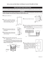
Check the minimum spacing needs as shown in Figs. 2
and 3, pages 6 and 7.
The top of the furnace must be at least 4 inches from the
ceiling. See Fig. 2.
With standard furnace discharge outlet, do not install
closer than 4 inches to intersecting wall. See Fig. 3B,
page 7.
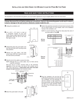
When using optional kits 6703 or 6704 maintain clearances
as shown in Figs. 3A or 3C, page 7.
When using optional kit 6704 maintain clearance as shown
in Figs. 3A and 3F, page 7. Use only optional outlet and
grille kits available from manufacturer.
RNISHED FLOOR
O" MIN.
FOR EXCEPllONS
TO MIN. SIDE
WALL CLF_CE
_RG.S 3A. ,.3C
,'.'_ k 3F
--6--

Locating Wall Furnace & Thermostat (Con't)
_/4"MIN WHEN
OPTIONAL ONE-WAY
FRONT DEFLECTING
GRILLE IS USED
....,%
A. 3/4 "_- _
12 ¸' _
12"MIN WHEN OPTIONAL
T W0 -WAY F_ONT
DEFL [CTING GRILLE
rS USED C.
FJT 67_
OPTIONAL ON[- _'_ I,_- 3/4 MI%
WAY f_EAR GRILLE
0PTIONAo__
_IE-WAy
FRONT
GRILL[ -MI N
r2
E.
0 _ I_llM A X
GRIU-E IS US[D 1_4" _
B.
KIT I_01
OP_IONA_ rWO-WA_ _.
REAR GRILLE 2 ¸'_ I
D.
;_
Choose a location for the thermostat about 5 feet above
the floor on an inside wall. The thermostat wire supplied
with your furnace is 20 feet long, which should be enough
to run up through the attic sothe thermostat can be a max-
imum of 16 feet from the furnace measured in a straight
line, or approximately 12 feet from the furnace if the wire
is run under the floor. The thermostat should be sensing
average room temperature, avoid the following:
HOT SPOTS:
Concealed pipes or ducts
Fireplaces
Registers
TV sets
Radios
Lamps
Direct sunlight
Kitchen
COLD SPOTS:
Concealed pipes or ducts
Stairwells - drafts
Doors - drafts
Unheated rooms on
other side of wall
DEAD SPOTS:
Behind doors
Corners, and alcoves
After picking a locationthat meets the requirements, check
the walls, attic and roof to make sure there are no obstruc-
tions such as pipes, electric wiring, etc., which could in-
terfere with the installation of the furnace or vent pipe. If
required, move them or pick a new location.
WARNING
DANGER OF PROPERTY DAMAGE, BODILY IN-
JURY OR LOSS OF LIFE. DO NOT INSTALL
FURNACE IN ANY AREA WHERE OXYGEN IS IN
USE.
Combustion & Ventilation Air
WARNING
DANGER OF PROPERTY DAMAGE,
BODILY INJURY OR DEATH
THE FURNACE AND ANY OTHER FUEL BURNING
APPLIANCE MUST BE PROVIDED WITH ENOUGH
FRESH AIR FOR PROPER COMBUSTION AND
VENTILATION OF FLUE GASES. MOST HOMES
WILL REQUIRE THAT OUTSIDE AIR BE SUPPLIED.
The high cost of energy for home heating has brought
about new materials and methods used to construct or
remodel most current homes. The improved construction
and additional insulation has reduced the heat loss and
made these homes much tighter around windows and
doors so that infiltrated air is minimal. This creates a pro-
blem to supply combustion and ventilation air for gas-fired
or other fuel burning appliances. Any use of appliances
that pull air out of the house (clothes dryers, exhaust fans,
fireplaces, etc.) increases this problem and appliances
could be starving for air.
In addition, these energy measures mean that your
home will retain more water vapor or a higher relative
humidity.
High humidity, especially during cold weather, may be
damaging to buildings because condensation forms on
windows and inside walls.
The combination of a tight energy efficient home with the
use of exhaust fans, fireplaces, clothes dryers, and gas
appliances results in more and more air being drawn
from the house until fresh air may be sucked in to the
house down the furnace flue or fireplace chimney.
Carbon monoxide can be the result. Carbon monoxide or
"CO" is a colorless, odorless gas produced when fuel
is not burned completely or when the flame does not
receive sufficient oxygen. Automobiles, charcoal, wood
fires and improperly vented or air-starved coal, oil and gas
furnaces or other appliances can produce carbon
monoxide.
Be aware of these air-starvation signals:
1. Headaches, nausea, dizziness.
2. Excessive humidity - heavily frosted windows, moist
"clammy" sensation.
3. Fireplace smokes, won't draw.
4. Furnace flue backs up.
--7--

Combustion & Ventilation Air (cont.)
AIR REQUIREMENTS
The requirements for providing air for combustion and
ventilation are listed in the National Fuel Gas Code NFPA
54/ANSI Z223.1 (in Canada: CAN/CGA B149). Most homes
will require that outside air be supplied to the furnace area
by means of ventilation grilles or ducts connecting direct-
ly to the outside or spaces open to the outdoors such as
attic or crawl space. The only exception is when the fur-
nace area meets the requirements and definitions for an
unconfined space with adequate air infiltration.
WARNING
DANGER OF PROPERTY DAMAGE,
BODILY INJURY OR DEATH
THE FURNACE AND ANY OTHER FUEL BURNING
APPLIANCE MUST BE PROVIDED WITH ENOUGH
FRESH AIR FOR PROPER COMBUSTION AND
VENTILATION OF FLUE GASES. MOST HOMES
WILL REQUIRE THAT OUTSIDE AIR BE SUPPLIED.
All air openings and connecting ducts must comply with
the following:
IF THE FURNACE IS INSTALLED IN AN AREA WITH
ANOTHER GAS APPLIANCE(S), THE TOTAL INPUT
RATING OF ALL APPLIANCES MUST BE CONSIDERED
WHEN DETERMINING THE FREE AREA RE-
QUIREMENTS FOR COMBUSTION AND VENTILATION
AIR OPENINGS.
Ducts must have the same cross-sectional area as the free
area of the openings to which they connect.
The minimum dimension of rectangular air ducts must not
be less than 3 inches.
LOUVERS / GRILLES AND SCREENS
COVERING FREE AREA OPENINGS
If screen is used to cover opening(s), it must not be smaller
than 1/4 inch mesh. Use the free area of a louver or grille
to determine the size opening required to provide the free
area specified. If the free area is not known, assume a
20% free area for wood and a 60% free area for metal
louvers or grilles.
EXAMPLE 1.
FURNACE LOCATED IN UNCONFINED SPACE.*
*An unconfined space must have a volume of a minimum
50 cubic feet per 1000 Btuh of total of all appliances in
area. Adjoining rooms may be included only if there are
no doors between the rooms, or if special provisions are
made such as ventilation grilles installed between con-
necting rooms.
Fig 6, page 9 shows the minimum area in square feet, bas-
ed on 8 foot ceiling heights, required for different Btuh
input ratings.
A. If your furnace is in an open area (unconfined space*)
the air that leaks through the cracks around doors and
windows may be enough for combustion and ventila-
tion air. The doors should not fit tight. The cracks
around windows should not be caulked or weather
stripped.
To determine if infiltration air is adequate, perform the
following checks:
1. Close all doors and windows. If you have a fire-
place, start a fire and wait until flames are burning
vigorously.
DRAFT HOOD SPILLAGE
VENT PIPE
DRAFT HOOD
__MATCH
WATER
HEATER
__L
I
WALL
FURNACE
MATCH
DRAFT
HOOD
OPENING
2,
3,
Turn on all exhausting devices, such as:
- kitchen and bathroom exhaust fans
- dryers (gas and electric)
Turn on all vented gas appliances, such as:
- heating equipment (includes any room heaters)
- water heaters
4. Wait ten (10) minutes for drafts to stabilize.
5. Check for draft hood spillage at each appliance.
(Hold a lighted match 2 inches from draft opening.
See Fig. 4.)
B. No Spillage
Match flame pulls toward draft hood - this indicates
sufficient infiltration air:
1. Return exhausting devices and appliances to the
condition you found them.
C. Draft Hood Spills
If there is spillage at a draft hood (match goes out or
flame wavers away from draft hood):
1. Check for plugged flue connectors and chimneys.
Check and repair stoppage and test again.
2. If you have a fireplace, open a window or door near
the fireplace and then check for spillage.
a. If spillage stops, do not use the fireplace without
a nearby window or door open until you can
supply fresh air by a permanent duct.
3. Ifyou have kitchen and bathroom exhaust fans, turn
them off and check for spillage.
a. If spillage stops, do not use exhaust fans until
you can supply fresh air by a permanent duct.
Circuit breakers for fans should be turned off if
possible.
m8--

Combustion & Ventilation Air (cont.)
WARNING,
DANGER OF PROPERTY DAMAGE,
BODILY INJURY OR DEATH
DRAFT HOOD SPILLAGE, WITH UNOBSTRUCTED
VENTS, INDICATES THAT ADDITIONAL AIR MUST
BE BROUGHT iNTO THE STRUCTURE FROM THE
OUTSIDE. KEEP A WINDOW OPEN (MINIMUM 2
INCHES) NEAR THE APPLIANCE UNTIL A PERMA-
NENT AIR DUCT iS INSTALLED.
4. Spillage means air starvation and a fresh air duct
or air intakes must be installed to provide air directly
to the furnace or other gas appliance.
D. If spillage exists or when the furnace is in a building
of tight construction where the windows and doors are
weatherstripped, air for combustion and ventilation
must be obtained from outdoors or space open to the
outdoors.
provided with free air for proper combustion and ventila-
tion of flue gases by one of the following methods.
A. All Air From Inside Building:
If the confined space adjoins an unconfined space as
defined in EXAMPLE 1,provide two permanent openings,
one within 12 inches of the top and one within 12 inches
of the bottom of the room connecting directly to unconfin-
ed space. Each opening must have a free area of at least
100 square inches or 1 square inch per 1000 Btuh com-
bined input of appliances in one room if combined input
exceeds 100,000 Btuh.
WARNING
DANGER OF PROPERTY DAMAGE,
BODILY INJURY OR DEATH
THE ADJOINING UNCONFINED SPACE MUST
HAVEADEQUATE AIR INFILTRATION AS DEFINED
IN EXAMPLE 1.
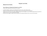
Provide an opening(s) having a total free area of 1 sq.
inch per 4000 Btuh of the total of all appliances. The
required area is shown in Fig. 9, page 10 under the
column for (40,000).
FRESH AIR DUCT
HOLES FROM VENTILATED
ATTIC INTO STUD SPACE
SEE FIG 8
AIR GRILLE TO STUD SPACE
12" MAXFROM FLOOR
HOLES FROM VENTILATED
CRAWL SPACE INTO STUD SPACE
SEE FIG 8
HOLE IN BOTTOM OR
BACK OF FURNACE
INTO OPEN STUD SPACE OR CRAWL SPACE
Fig. 5 shows a typical duct going into ventilated crawl
space or attic.
1. Duct must terminate at a point not more than 1 foot
above the floor.
2. Duct size must be at least 1 inch of free area for
each 4000 Btuh of input of all appliances in area.
EXAMPLE 2.
FURNACE LOCATED IN CONFINED SPACE.
If furnace is installed in a confined space, it must be
FOR EXAMPLE: Your furnace is rated at 50,000 Btu per
hour.The water heater israted at 30,000 Btu per hour.The
totalis80,000 Btu per hour.You need two grilles,each with
100 square inchesoffree opening. Metal grilleshaveabout
60% free area, so you need two metal grilles each with
160 square inches of Iouvered area.
Refer to Fig. 7, page 10, which shows grille installation.
Using the previous example, the two connecting rooms
plus the closet must equal at least 500 sq. feet to handle
the combined input 50,000 plus 30,000.
4000 Btuh Per
Square lnch
Opening
Round Rectangular
MINIMUM AREA IN SQUARE FEET
Duct
4" DIA.
4" DIA.
4" D[A.
4" DIA,
4" DIA.
4_ '' DIA
Duct
3"x3" SQ.
3"x3" SQ.
3"x4" SQ.
3"x4" SQ.
3"x5" SQ.
3"x5" SQ.
Max. Btuh
Input
30,000
35,000
40,000
45,000
50_00
60_00
*Unconfined Space
Min. Area In Sq. Ft.
8' Ceiling Height
188
219
250
281
312
375
*Can be two or more rooms joined by ventilation grilles.
B. All Air From Outdoors:
If confined space doesn't adjoin an unconfined space
(defined in EXAMPLE 1) then air must be provided from
outdoors or spaces open to outdoors such as attic or crawl
spaces.
Provide two permanent openings, one within 12 inches of
top, one within 12 inches of bottom of room connecting
directly, or by using ducts, with the outdoors or areas open
to outdoors.
If opening connects directly to, or within vertical duets,
the free area of each opening must be at least 1 square
inch per 4000 Btuh combined input of appliances in area.
m9--

Combustion & Ventilation Air (cont.)
If horizontal ducts are used, the free area of each open-
ing must be at least 1 square inch per 2000 Btuh com-
bined input of appliances in area.
GRILLES CONNECTING ROOMS TO MAKE
UNCONFINED SPACE
FOR EXAMPLE: Your furnace is rated at 80,000 Btu per
hour. The water heater is rated at 30,000 Btu per hour. The
total is 80,000 Btu per hour. You need two grilles, each with
20 square inches of free opening, unless connected by
horizontal ducts which would require each grille or open-
ing to have a free area of 40 square inches.
*Openings for inlet or outlet air should not be made into
attic area if attic is equipped with a thermostat controlled
power vent.
FREEAREA IN SQ.INCHES - EACHOPENING (FURNACE
ONLY) - BASEDON ONE SQ. INCH PER 4000 8TUH
Furnace
Btuh / Input
30,000
35,000
40,000
45,000
50,000
60,O00
Req'd Number of Holes
Sq, Inch Sill or Header Plates
of Opening 1_/2'' 2" 3"
7.5 7 4 2
8.75 8 5 2
10.0 9 5 3
11.25 10 6 3
12.5 11 6 3
15.0 13 8 4
Recessed Mount Installation
FIND THE STUDS (See CAUTION on page 6)
CUT WALL OPENING
Use a stud Iocator or small finishing nails. Repeatedly
drive and remove a nail into the wall in the area of the
stud until it is located. Then find the inside edge of the
stud. Leave the nail at this location.
The other stud should be about 14-1/2 inches from the
one found. Drive finishing nails on the insides of this stud.
Draw wall cut out to required size as shown in Fig. 13,
page 12. If wall studs are not on 16 inch centers see
"CLOSE OFF STUD SPACE," Fig. 12, page 12.
Provide an opening as shown in Fig. 10, page 11. Work
from the top in the attic to cut away the ceiling plate.
ATTACH HEADER PLATE
MODELS: 5508331; 5508332; 6508731; 6508732
Locate header plate (Fig. 10, page 11) between wall studs
at 88V2 inches from finished floor and nail into position
with end flanges pointing up.
--10--

Recessed Mount Installation (cont.)
See Fig. 10.
MODELS: 5008731; 5008732
Locate header plate between wall studs at 821/2 inches
from finished floor and nail into position with end flanges
pointing up.
GAS SUPPLY OPENING
A hole must be drilled for the gas line supply.
Decide whether the gas line will come through the floor
or wall stud.
NOTE
MODELS: 3508331; 3508332; 3508731; 3508732
Locate header plate between wall studs at 74 inches from
finished floor and nail intoposition with end flanges point-
ing up,
If a pre-existing gas piping stub location is not compati-
ble with hole or knock-out provided in furnace, you may
make an alternate entry hole in furnace back wall per Fig.
13, page 12.
ALL MODELS
Hole for electrical conduit is located on left side of header
plate as you face the wall.
CAUTION
Be careful not to damage any furnace components
while making any alternate hole.
WARNING
REMOVE 4x14 FIBERGLASS GASKET FROM BOT-
TOM OF HEADER PLATE AND DISCARD. THIS
GASKET IS NOT USED WHEN THE FURNACE IS
RECESSED IN THE WALL.
Locate and drill one (1) 1-1/2 inch hole at selected loca-
tions per Fig. 11 and Fig. 13, page 12 or Fig. 14, page !3.
Gas line can be run at this time or done after furnace
is mounted, see section GAS SUPPLY AND PIPING,
page 17.
F-
_LEXIBLE
ELECTRIC,
ONDUIT
CONVENI ENCE-_
OUTLET
f -- . j
B/W VENT PIPE
(NOT SUPPLIED)
7_r HOLD-DOWN OR
STARTER PLATE
_(NOT SUPPLIED)
/
N
HEADER
PLATE
,'- FINISH
FLOOR
/
/
N01_:
WALL BOARD &
FLOOR PLAI_
REMOVEDFOR
RECIE_ MOUNT
ONLY
2"
SURFACE _ MOUNTING
MOUNTING
CLOSE OFF STUD SPACE (If Required)
If studs are not on 16 inch centers, cut the hole for the
furnace next to an existing stud and frame in the other side
using a 2 x 4 and spacer blocks as required. See Fig. 12,
page 12.
ELECTRICAL SUPPLY ROUGH-IN
Run the electrical supply with the ground wire and ther-
mostat cable into stud space above furnace location.
--11 m

Recessed Mount Installation (cont.)
CLOSE OFF STUD SPACE (If Required)
7
PLA'I_
E_S71NG S31JDt
]
I -- 14-_/8"_-
1
F I_]b-I1NG b-lUD
Ill
II NEW S'IUD
111
III
%
SPACER
III
H I
..... LI-1 r-!U-I......
If desired, the power supply and thermostat cable can
come into the wall stud space from a basement, crawl
space or an adjoining stud space.
Terminate flexible electrical conduit at the junction box
located on the underside of the header plate. Leave the
wires long enough to connect inside the junction box to
the convenience outlet.
CAUTION
Do not run wire behind flanges of header plate or
in any location where it might be damaged. Avoid
splicing thermostat wire unlessthe spliced wires are
properly cleaned, soldered and taped.
.,_,- FRONT
TOP ELEC
_,/" CONN.
[41C ",+--141/6"-_-
BOTTOM
(1) MODELS: 5508331; 5508332;
6508731 ; 6508732
(2) MODELS: 5005731; 5008732
(3) MODELS: 3508331; 3508332;
3508731; 3508732
Surface Mount Installation
FIND THE STUDS AND CEILING JOISTS
(See CAUTION on page 6)
Find two studs at spot where furnace is to be placed.
Use a stud indicator or small finishing nails. Repeatedly
drive and remove a nail into the wall in the area of the
stud until you find it. Then find one side. Leave the nail
there. Drive another nail just on the other side of the same
stud.
Inside edge of the other stud should be about 14-1/2
inches from the one found. Drive finishing nail on inside
edge of this stud.
Using the nails as a guide, draw a line up both sides to
the ceiling to locate hole cut out for vent pipe and elec-
trical connections.
CUT CEILING OPENING
Mark off and cut 3-1/2 x 12 inch rectangular hole in ceil-
ing, centered between wall studs. The back edge of the
opening should be about 1/8 inch from the wall. See Fig.
16, page 14.
ELECTRICAL SUPPLY ROUGH-IN
The electrical supply openings must be made in the wall
or ceiling above furnace to match holes in furnace top.
Holes in furnace top are 1 inch from the left side of fur-
nace. See Fig. 13.
If desired, the power supply and thermostat cable can
come into the wall stud space from a basement, crawl
space or an adjoining stud space.
--12--

Surface Mount Installation (cont.)
At selected location, drill a 1 inch hole for 115V power
supply and a 1/2 inch hole for the thermostat cable.
Run wiring through holes to above furnace top leaving
enough excess wire to make electrical connections after
mounting furnace.
CAUTION
I e careful not to damage any furnace components
while making any alternate hole.
Locate and drill one (1) 1-1/2 inch hole at selected loca-
tion per Fig. 11, page 11; Fig. 13, page 12; or Fig. 14.
CAUTION
Toavoiddamage towiring, be sure to routewire away
from path of furnace vent.
GAS SUPPLY OPENING
A hole may need to be drilled for the gas line supply.
Decide whether the gas line will come through the floor
or wall.
NOTE
If you decide to route gas line through right side of fur-
nace, simply remove the knock-out provided in furnace
side.
NOTE
If a pre-existing gas piping stub location is not compati-
ble with hole or knock-out provided in furnace, you may
make an alternate entry hole in furnace back wall per
Fig. 14.
Gas line can be run at this time or done after the furnace
is mounted, see section CONNECTING GAS LINE.
ALTERNATE GAS SUPPLY OPENING
ALTERNATE GAS SUPPLy---"%._I )--'t
ENTRy LOCA]10N
?
GAS SUPPL_
ENTRy HOLES
r;
General Vent Installation
The vent installation must comply with all local codes and
ordinances. If in doubt, consult your local codes or
inspector.
The furnace vent must be directed to the outdoors so that
harmful combustion gases will not collect inside the
building.
This furnace must not be connected to a chimney flue
serving a separate solid-fuel burning appliance.
Use U.L. listed B/W Vent Kit 9901. You must provide other
items, not contained in kit, necessary to complete your
specific venting situation through the roof. Refer to typical
venting system shown in Fig. 18, page 15.
Type B/W gas vent shall extend from the header plate of
the vented wall furnace to a point above the highest ceil-
ing plate within a stud space through which the vent
passes, without any offsets or crossovers thei'ein. After a
type B/W gas vent passes through the highest ceiling
plate within a stud space above the furnace which it
serves, the vent system may be completed with a type B
gas vent, of the same manufacturer, and offsets or
breakovers shall not be greater than 45 degrees from
vertical.
NOTE
The B/W vent must extend through the ceiling and roof
terminating at least 12 feet above the finished floor on
which the furnace rests.
First vent pipe offset (if required) is recommended not to
be any closer than 2'-0" from header plate.
ATTACH HEADER & HOLD-DOWN PLATE
(SURFACE MOUNT)
Remove the fiberglass flue collar from the furnace flue
extension. This gasket is not used when the furnace is sur-
face mounted.
Make sure that the 4 x 4 inch gasket is in position on the
header plate.
--13--

General Vent Installation (cont.)
Discard the three (3) square gaskets, as they are not used
when furnace is surface mounted.
INSTALL CEILING PLATE SPACERS
(SURFACE MOUNT)
Slide header plate over the furnace flue extension with the
junction box entering the opening in top of furnace.
Refer to Fig. 15.
Refer to Fig. 16.
Only one (1) plate spacer is required for surface mount-
ing within a single story dwelling.
Fasten to matching holes in the furnace top through holes
"A" in the header plate, using two (2) #8 x 3/8 inch screws
provided.
Fasten the hold-down plate or starter plate to the top of
the header plate using holes "B" in the header plate.
Cut 2 inches off each end of plate spacer.
Drill two (2) 3/16 inch holes in each end of plate spacer.
See Fig. 18, page 15.
Fasten plate spacer to wall by nailing through one (1)
drilled hole in each end, into the wall board and ceiling
plate.
j ,,g,,
INSTALL CEILING PLATE SPACER
(RECESSED MOUNT)
Refer to Fig. 17.
Two ceiling plate spacers are in the B/W vent kit. They
mustbe fastened along each longedge ofthe ceiling hole
to hold the oval vent pipe in the center of the hole.
ALL MODELS
ATTACH HOLD-DOWN PLATE (RECESSED MOUNT)
Nail the ceiling plate spacers either across or in between
the cut out section of ceiling plate. If nailed between, ends
must be bent at 90 degrees.
NOTE
Header plate should already be attached to wall studs. See
ATTACH HEADER PLATE, page 10 and 11.
Fasten hold-down plate to top of header plate using two
(2) screws provided.
"_" r,_4_3V2 CENTERED ON
!1 a/w VENT
TOP ___ HOLE IN
HOLD-DOWN OR
RTER PLATE
r_ (NOT SUPPLIED)
HEADER PLATE
SIDE
CEILING PLATE
FRONT
CEILING PLATE SPACERS - RECESSED MOUNT
_ 14 318
INSTALL SURFACE VENT (SURFACE MOUNT)
NOTE
For surface mounting, it willbe helpful to complete the gas
piping supply to the furnace before installing the vent pipe.
See section GAS SUPPLY & PiPiNG, page 17.
Carefully move the furnace into position under the ceiling
cutout.
Insert first lengths of oval, double wall vent pipe up through
the ceiling cutout.
--14 m

General Vent Installation (cont.)
TYPICAL VENT INSTALLATION
1
Vl_IT CAP "rOBE AMINo OF2 FT. HIGHER
THANANY pOINT _ 10 FT. OF _rr C_
HEADER PLA1E
2 E_DS
FLUE
COLLAR
QAS_£T
Lower vent pipe to the hold-down plate. Push the vent
pipe into the hold-down plate until it is completely
seated. (Hold-down cleats will engage the groove in the
vent pipe.)
Secure hold-down plate to vent pipe using two (2) screws.
Using plumbers tape to secure vent to the plate spacer,
nail through one (1)hole in each end of plate spacer, into
the wall and ceiling plate.
INSTALL FURNACE VENT (RECESSED MOUNT)
Lower first lengths of oval, double wall vent pipe through
the plate spacers to the hold-down plate.
Push the vent pipe into the hold-down plate until it is com-
pletely seated. (Hold-down cleat will engage the groove
in the vent pipe.)
Secure hold-down plate to vent pipe using two (2) screws.
COMPLETE THE VENTING
Refer to Fig. 18.
Install oval to round adapter. Complete the piping extend-
ing it through the roof. Use 4" round, double wall (Type
B) vent pipe, roof flashing, storm collar, and vent top as
shown. The vent cap must be at least 2 feet higher than
any point that is within 10 feet horizontally of the vent cap.
There must be at least 1 inch clearance between the vent
pipe and any combustible material.
IMPORTANT
Area above header within the stud space MUST be kept
clear of any attic insulation to allow the free circulation of
air around oval vent piping.
Mounting Your Furnace
To obtain adequate clearance for fastening furnace or to
install gas supply fittings, it may be necessary to remove
the burner and control assembly as follows:
Remove burner compartment door by pulling door top out
and up.
Locate the air discharge shield. It is secured across the
top of the burner control compartment. Remove two (2)
screws and shield and set aside.
DISCONNECT WIRING
MODELS 3508331; 3508332; 5508331; 5508332
Remove the screws holding the ignition control unit and
cover to the furnace casing.
Disconnect wires to free control module from its mount-
ing location. Mark or tag each wire removed for its exact
reconnection. See Fig, 19, page 16,
ALL OTHER MODELS
Disconnect two (2) 24 volt wires from the gas valve.
Disconnect two (2) wire connectors from junction block
midway on the thermocouple.
REMOVE BURNER AND CONTROLS
MODELS: 3508331; 3508332; 3508731; 3508732
Locate the burner and screwsthat secure it. Remove the
two (2) screws (one from each end). Lift one end of the
burner at a time until free. Remove burner and controls
from the compartment.
ALL OTHER MODELS
Locate the burner and hex nuts that secure it. Remove
the two (2) hex nuts (one from each end). Flip up the wire
hinges. Lift one end of burner at atime until free. Remove
burner and controls from the compartment.
--15--

Mounting Your Furnace (cont.)
Straighten the furnace by pushing furnace bottom intothe
stud space.
24V
PV
SEt6
24V
GND
lnV
GND
WILLIAMS IGNITION CONTROL
PART NUMBER P321910
LA707-01 .DWG
POSITION FURNACE (RECESSED MOUNT ONLY)
NOTE
If your furnace is surface mounted, your mounting was
started during VENT INSTALLATION, page 13.To complete
furnace mounting, go on to FASTEN FURNACE BOTTOM
on this page.
ALL MODELS
Make sure that the flue collar gasket, Fig. 18,page 15, is
in place over the flue extension. Check to see if header
plate gaskets are in place.
Hold the furnace at a slight angle (top closer to the wall
than bottom) with the flue extension centered under the
oval hole in the header plate.
NOTE
Electrical wiring should already be routed to the header
plate. If not, see sections on ELECTRICAL SUPPLY
ROUGH-IN, page 12.
Place three (3) square gaskets over the junction box. See
Fig. 18, page 15.
ALL MODELS
Lift furnace up so that the flue extension enters the oval
hole in the header plate.
IMPORTANT
AFTER FURNACE HAS BEEN PLACED IN POSITION,
MAKE SURE THE GASKETS ARE PRESSING AGAINST
THE FURNACE TOP TO ELIMINATE AIR LEAKS.
FASTEN FURNACE BOTTOM
(SURFACE AND RECESSED MOUNT)
NOTE
Fasteners are not furnished because of different require-
ments of various types of wall construction.
Fasten furnace to floor through holes provided in furnace
bottom. If you have concrete flooring, use an alternate
fastening method. See Fig. 20.
If burner and control assembly were removed, replace
them by reversing "DISCONNECT WIRING" and
"REMOVE BURNER AND CONTROLS" sections on
page 15.
FURNACE MOUNTING
- METAL ANOH(_
TOP FASTENING
II
I
I
NOTE: DO NOT U_ BOTTOM DOOR _ FOR MOUNTING
--16--

IMPORTANT
Mounting Your Furnace (cont.)
TO PREVENT DAMAGE TO WIRING, MAKE SURE
NOT TO PINCH THE WIRES BETWEEN FURNACE
COMPONENTS. KEEP THEM ROUTED AWAY FROM
THE BURNER.
Resecure the air discharge shield across the top of the
burner and controls compartment, Small leg of "L" shape
must be positioned toward floor, pointing away from front
of furnace.
over the back flange of furnace top and screwing to wall.
See Fig. 20, page 16.
FASTEN FURNACE TOP (RECESSED MOUNTING)
Fasten furnace top by drilling two (2) holes through the
side flanges of furnace top and securing with two (2)
screws or nails into the wall studs. See Fig. 20, page 16.
FASTEN FURNACE TOP (SURFACE MOUNTING)
Fasten furnace top to wall using two (2) metal anchors
(packed in plastic bag with thermostat) by placing them
CAUTION
Becareful notto damage furnace components or wir-
ing when drilling holes,
Gas Supply and Piping
Gas control valve, within the furnace, is shipped with a
seal over gas inlet tapping. Do not remove seal until ready
to connect piping.
WARNING
DANGER OF PROPERTY DAMAGE,
BODILY INJURY OR DEATH.
MAKE SURE THE FURNACE IS EQUIPPED TO
OPERATE ON THE TYPE OF GAS AVAILABLE.
MODELS DESIGNATED AS NATURAL GAS ARE TO
BE USED WITH NATURAL GAS ONLY, FURNACE
DESIGNATED FOR USE WITH LIQUIFIED
PETROLEUM (L.P) GAS HAVE ORIFICES SIZED
FOR COMMERCIALLY PURE PROPANE GAS,
THEY CAN NOT BE USED WITH BUTANE OR A
MIXTURE OF BUTANE AND PROPANE.
GAS SUPPLY
For Natural gas, the minimum inlet gas supply pressure
for the purpose of input adjustment is 5" water column.
The Maximum inlet gas supply pressure is T' water
column.
For L.E gas, the minimum inlet gas supply pressure for
the purpose of input adjustment is 11" water column. The
maximum inlet gas supply pressure is 13" water column.
Gas pressure and input to the burners must not exceed
the rated input and pressure shown on the rating plate. On
Naturel Gas the manifold pressure should be 4 inches
water column. The manifold pressure should be 10.5 inch-
es water column for L.P. Gas. See page 32 for operation
above 2000 feet altitude Office change may be required to
suit gas supplied. Check with your local gas supplier.
ORIFICE SIZES
Furnace Technical Information, page 32, shows the
correct orifice sizes for the different input ratings when
using Natural or L.P Gas.
GAS PIPING
The gas supply line must be of adequate size to handle
the BTU/HR requirements and length of the run for the
unit being installed.
Determine the minimum pipe size from Fig. 23, page 18,
basing the length of the run from the gas meter or source
to the unit.
DROP
I PIPED CR0UN0 JOINT
i_ I GAS aN,0N
SUPPLy
tlANUAL SHUT OFF
VALVE
DF(Op
--17--

Gas Supply and Piping (cont.)
PROPER PIPING PRACTICE
2 IMPERFECT CONTRO L USE MODERATE AMOUNT OF DOPE
THREADS _
THREAD PIPE RIGHT LENGTH LEAVE 2 END THREADS [IARE "
All piping must comply with local codes and ordinances
or with the National Fuel Gas Code (ANSI Z223.1),
whichever applies. In Canada: Follow CAN 1-B149Installa-
tion Code.
Refer to Fig. 21, page 17,for the general layout at the unit.
It shows the basic fittings needed.
The following rules apply:
1. Use new, properly reamed pipe free from chips such
as steel or black iron pipe and fittings or other
approved by local codes.
2. Do not thread pipe too far. Valve distortion or mal-
function may result from excess pipe within control.
Apply moderate amount of good quality dope to pipe
only, leaving 2 end threads bare. If LP Gas installation,
use compound resistant to action of liquified petroleum
gases.
3. Use ground joint unions.
4. Install a drip leg to trap dirt and moisture before it can
enter the gas valve. Drip leg must be a minimum of 3
inches long.
5. Install a manual shut-off valve.
6. Provide a 1/8 NPT test gauge connection immediately
before the gas supply connection to the furnace.
GAS CONNECTION
If installation is for L.R Gas, have L.R installer use two-
stage regulation and make all connections from storage
tank to furnace.
Use two pipe wrenches when making the connection to
the valve to prevent turning or damage to gas valve.
Connection between manual shutoff valve and burner con-
trol assembly can be made with an A.G.A./C.G.A. design
certified flexible connector if allowed by local codes. Drip
leg and ground joint union are still required.
Tighten all joints securely.
CHECKING THE GAS PIPING
Test all piping for leaks. When checking gas piping to the
furnace with gas pressure less than 1/2 PSI, shut off
manual gas valve for the furnace. If gas piping is to be
checked with the pressure at or above 1/2 PSI, the fur-
nace and manual shut off valve must be disconnected dur-
ing testing. (SEE WARNING BELOW.) Apply soapsuds (or
a liquid detergent) to each joint. Bubbles forming indicates
a leak. Correct even the slightest leak at once.
GAS PIPE SIZES
NATURAL GAS
PIPE CAPACITY - BTU PER HOUR
(INCLUDES FITTINGS)
PIPE SIZE
LENGTH OF
PIPE - FEET 1/2 inch 3/4 inch 1 inch
20 92,000 190,000 350,000
40 63,000 130,000 245,000
60 50,000 105,000 195,000
L.P. GAS
PIPE CAPACITY - BTU PER HOUR
(INCLUDES FITTINGS)
LENGTH OF
PIPE - FEET 1/2 inch 3/4 inch 1 inch
20 189,000 393,000 732,000
40 129,000 267,000 504,000
60 103,000 217,000 409,000
WARNING
DANGER OF PROPERTY DAMAGE,
BODILY INJURY OR DEATH.
NEVER USE A MATCH OR OPEN FLAME TO TEST
FOR LEAKS. NEVER EXCEED SPECIFIED
PRESSURES FOR TESTING. HIGH PRESSURES
MAY DAMAGE THE GAS VALVE AND CAUSE
OVER-FIRING WHICH MAY RESULT IN HEAT
EXCHANGER FAILURE. LIQUID PETROLEUM
(L.P.) IS HEAVIER THAN AIR AND IT WILL SETTLE
IN ANY LOW AREA, INCLUDING OPEN DEPRES-
SIONS AND IT WILL REMAIN THERE UNLESS
AREA IS VENTILATED.
NEVER ATTEMPT STARTUP OF UNIT BEFORE
THOROUGHLY VENTILATING AREA.
Electrical Wiring
All electrical work must conform to your local codes and
ordinances or in their absence, with National Electrical
Code, ANSI/NFPA 70. If you are not familiar with wiring
codes, in general, have a competent electrician do this
job. In Canada: Follow C22.1, Canadian Electrical Code.
ELECTRICAL CONNECTION
REMOVE FAN SHROUD
Take out four screws holding fan shroud to side flanges
of cabinet and remove shroud. See Fig. 1, page 5.
m18m

WARNING
DANGER OF PROPERTY DAMAGE,
BODILY INJURY OR DEATH.
TURN OFF ELECTRIC POWER AT FUSE BOX
OR SERVICE PANEL BEFORE MAKING ANY
ELECTRICAL CONNECTIONS.
INSULATE WHERE NECESSARY.
ALL LINE VOLTAGE AND GROUND CONNEC-
TIONS MUST BE COMPLETED BEFORE
ELECTRICAL POWER IS RESTORED.
ELECTRICAL POWER SUPPLY
A branch circuit including this furnace must not exceed
15 Amperes, or run a separate 115V,60 Hz, 15 Ampere
circuit from a separate circuit breaker or fuse in your ser-
vice entrance panel to the furnace junction box. Do not
run supply wires inside the furnace cabinet, except from
the top of cabinet down to junction box.
JUNCTION BOX
CAUTION
]
Be careful not to damage the fan blade when mak- 1
ing the 115V connection to the convenience outlet.
I
115V supply wiring connection is made within the upper
left corner of the furnace cabinet.
Locate 115V plug and push into the convenience outlet
attached to the bottom of header plate. (It protrudes
through the rectangular opening in the furnace top.)
LOW VOLTAGE CONNECTIONS
CAUTION
The Heat Anticipator WILL BURN OUT if 24 voltsare
applied directly to thermostat by shorting out the gas
valve or primary control during testing or by incorrect
wiring.
WALL THERMOSTAT WIRING
Run thermostat wire to the furnace.
Avoidsplicingthermostat wire unlessthe spliced wires are
properly cleaned, soldered and taped.
Connect thermostat to two wires marked "Thermostat"
extending from top of furnace, using two wire nuts pro-
vided. See Wiring Diagrams, pages 37 or 38.
CAUTION
Do not connect 115V service line to the gas control
valve or the wall thermostat.
ALL MODELS
Reinstall fan shroud to furnace front. Slots in fan shroud
allow up/down adjustment. Make sure the fan blade spins
freely. Tighten screws securely.
Replace top front panel and secure with thumbscrew.
Refer to paragraph covering GAS AND ELECTRICAL
SUPPLY OPENINGS, page 13. Follow Wiring Diagrams,
pages 37 or 38.
If you have any doubt regarding electrical hookup, or com-
pliance with code or ordinance, consult your electrical in-
spector or a licensed electrician.
GROUNDING
A ground lug is installed for the ground connection. Use
a copper conductor (#14 AWG) from the unit to a ground-
ed connection in the electric service panel or a properly
driven and electrically grounded ground rod.
COMPLETE WIRING DIAGRAMS ON PAGES 37 AND 38.
I19--

Thermostat Installation
1. If an old thermostat is being replaced and is in a
satisfactory location and the wiring appears to be
in good condition, use existing wiring. If in doubt, use
new wire.
2. If a new location is chosen or if this is a new installa-
tion, thermostat cable must first be run to the location
selected. All wiring must agree with local codes and
ordinances. These instructions cover bringing the wire
down from the attic but it can be run from a basement
or crawl space using similar methods. Refer to Fig. 24.
3. Before drilling hole in wall at selected location, drive
a small finishing nail through the ceiling in the corner
of the wall and ceiling above the thermostat location.
Pull the nail out and push a small stiff wire through the
hole so it can be found in the attic. Drill a 1/2 inch hole
through the ceiling wall plate.
4. Probe for obstructions in the partition. Then drill a 1/2
inch hole through wall at selected location for
thermostat.
5. From the attic, feed the thermostat cable or a stiff wire
through wall until even with thermostat location.
6. Snag thermostat cable through hole and pull cable
through hole in wall so that 6 inches of cable protrudes.
7. Route cable to wall furnace.
ROUTE THERMOSTAT CABLE
Ske,AL t
FINISH
NAIL TO
LOCATE
HEADER
THERMOSIAT
CABLE
STIFF WIRE
TO SNAG
CABLE
MOUNTING THE THERMOSTAT
1. To remove thermostat cover, squeeze both sides and
lift. See Fig. 25.
2. 'Connect thermostat wires to the terminal screws on the
thermostat base.
3. Push any excess wire back through hole in wall and
plug hole with insulation to prevent drafts from affect-
ing thermostat operation.
4. Being sure to level thermostat for best appearance,
fasten thermostat base to wall through mounting holes
with screws provided.
5. Replace the thermostat cover.
THERMOSTAT HEAT ANTICIPATOR
SET THE THERMOSTAT HEAT ANTICIPATOR
A simple method of setting the heat anticipator in a 24-volt
thermostat (without an A.C. ammeter) is to first read the
label on the gas control valve and match its rating.
Example: If the ampere draw for the valve is .5 amps,
set thermostat heat anticipator at the same
setting (.5). (Fig. 26, page 21.)
ADJUST THERMOSTAT ANTICIPATOR
Many factors affect this setting -- room size, length ofther-
mostat wire, thermostat location, etc. Additional small
adjustments to increase or decrease heating cycles (4-6
per hour typical) may be required. If an amp meter is
available, see instructions supplied with thermostat.
SQUEEZE RR_4LY
SOl1"1SIDES
AND UFT 110
R£_IO_,_COVER
t,/_r/...oa.l=t_
NOTE
Use heavier wire size if more than 20 ft. of wire is required.
--20--
/