Page is loading ...

L8542589
02/2012 rev 1
BRAINY 24
UNIONE NAZIONALE COSTRUTTORI
AUTOMATISMI PER CANCELLI, PORTE
SERRANDE ED AFFINI

3
SHIELD
ANT
ANT
M1 M2
LAMP
24Vdc
SCA
PHOTO
TEST
II°CH/SERL
24Vac
Lock 12Vdc
10W (5s)
24Vac/dc
500mA max
(+) (-)
SWO1/ENC1
SWC1
SWO2/ENC2
SWC2
PHOT
PHOTC
STOP
OPEN
CLOSE
PED
P.P.
COM/ENC +
ENC -
COM/ENC+
F1
T 2A
DAS
J1 DAS
Open
DAS N.C.
J1 DAS
Close
DAS 8K2
2827
1 2 3 4 5 6 7 8 9 10 11 12 13 14 15 16 17 18 19 20 21 22 23 24 25 26
2827
8k2
DAS
32313029
+-
RADIO
U11
Code
____
F2:1.6AT (230V)
F2:3.2AT (115V)
L
N
1

4
SWO1/ENC1
SWO2/ENC2
ENC +
ENC -
F1
T 2A
DAS
2827
1 2 3 4 5 6 7 8 9 10 11 12 13 14 15 16 17 18 19 20 21 22 23 24 25 26
31303130
+-
R ADI O
U11
M1
+ s -
M2
+ s -
3+3 x 0.5mm
2
max 10m
Collegamento ENCODER
ENCODER WIRING
2
3
4
24V ac 24V ac
COM
NC NO
RX1TX1
24V ac 24V ac
COM
NC NO
RX2TX2
11
24Vac
COM PHOT COM PHOT-C
24Vac
12 11 1213 18 13 199 10
9 10
test1:on test2:ON
SCA
AUX1:0
AUX1:2
SERVICE/ZONE LIGHT
Service Light
AUX1:3
Zone Light
L N
Service/Zone
Light
230Vac
Relè 24Vac
32313029
24Vac/dc
500mA max
11 12
32313029
24Vac/dc
500mA max
11 12

14
EC Declaration of conformity
Declaration pursuant to Directives 2004/108/EC(EMC); 2006/95/EC(LVD)
Manufacturer:
Automatismi Benincà SpA
Address:
Via Capitello, 45 - 36066 Sandrigo (VI) - Italy
Declares that the product:
Command central for 1/2 24Vdc motor, for single or sliding doors: BRAINY 24
is compliant with the conditions of the following EC Directives:
• DIRECTIVE 2004/108/EC OF THE EUROPEAN PARLIAMENT AND COUNCIL of December 15 2004 regarding
the approximation of the legislations of the member States relative to electromagnetic compatibility and that repeals directive
89/336/CEE, according to the following concurred norms:
EN 61000-6-2:2005, EN 61000-6-3:2007.
• DIRECTIVE 2006/95/EC OF THE EUROPEAN PARLIAMENT AND THE COUNCIL of December 12 2006 concer-
ning the approximation of the legislations of the member States relative to electrical material destined to be used within certain
voltage limits, according to the following concurred regulations:
EN 60335-1:2002 + A1:2004 + A11:2004 + A12:2006 + A2:2006 + A13:2008; EN 60335-2-103:2003.
if applicable :
• DIRECTIVE 1999/5/EC OF THE EUROPEAN PARLIAMENT AND THE COUNCIL of March 9 1999 regarding radio
devices and terminal and telecommunications devices and the reciprocal recognisances of their conformity, according to the
following concurred regulations: ETSI EN 301 489-3 V1.4.1 (2002) + ETSI EN 301 489-1 V1.4.1 (2002) + ETSI EN 300 220-3
V1.1.1 (2000) + EN 60950-1 (2001)
Benincà Luigi, Legal manager.
Sandrigo, 02/11/2010.
WARNINGS
This manual has been especially written to be use by qualified
fitters.
None of the information provide in this manual can be considered
as being of interest for the end users.
Preserve this manual for future needs.
The technician has to furnish all the information related to the step
by step function, the manual and the emergency function of the
operator, and to deliver the manual to the final user.
•
Foresee on the supply net an onnipolar switch or se-
lector with distance of the contacts equal or superior
to 3 mms.
Verify that of the electrical system there is an awry differential
interrupter and overcurrent protection.
Some typologies of installation require the connection of the
shutter to be link at a conductive mass of the ground according
to the regulations in force.
The electrical installation and the operating logic must comply
with the regulations in force.
The leads fed with different voltages must be physically separate,
or they must be suitably insulated with additional insulation of
at least 1 mm.
The leads must be secured with an additional fixture near the
terminals.
During installation, maintenance and repair, interrupt the power
supply before opening the lid to access the electrical parts
Check all the connections again before switching on the po-
wer.
The unused N.C. inputs must be bridged.
The descriptions and the present illustrations in this manual are
not binding. Leaving the essential characteristics of the product
unchanged, the manufacturer reserves himself the right to bring
any change of technical, constructive or commercial character
without undertaking himself to update the present publication.

15
TECHNICAL DATA
Contol unit supply
24 Vdc
Power supply
230 Vac 50/60 Hz or 115Vac 50/60Hz according to the version
Output supply
1/2 motor 24Vdc
Maximum motor current
5+5 A
Output supply accessories
24Vdc 500mA max.
Protection level
IP55
Operating temp.
-20°C / +50°C
Radio receiver
built in 433,92 MHz confgurabile (rolling-code or programmable + rolling-code)
Rolling code transmitters supported
64
BRAINY 24 CONTROL UNIT
AUTOSET FUNCTION
IMPORTANT: The control unit is equipped with the Autoset function to automatically set the main functioning values based on the
type of installation.
The AUTOSET function must be repeated at every function parameter change or upon change of automation conditions. See the
AUTO menu for further information.
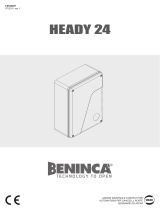
WIRE DIAGRAM
Wire connections shown in Fig. 1 are described hereunder:
Terminal No. Function Description
1-2 Motor 1 Connection, motor 1: 24VDC 5A max
3-4 Motor 2 Connection, motor 2: 24VDC 5A max
5-6 Flashing light Connection, flashing light 24VDC 15W max.
7-8 Lock Output, 12Vdc/10W power supply for electric lock (7:0V, 8:+12V)
9-10
SCA/
PHOTO TEST
Contact free from N.O. Voltage, may be configured as open gate indicator or photocell
test.
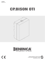
For use as “Open gate indicator” the TEST1 and TEST2 logics must be OFF
For use as photocell test it is sufficient to activate one or both TEST logics and connect
the photocells as indicated in Fig.3.
11-12 24 Vac/dc
Output, accessory power supply, 24VAC/0.5A max.
IMPORTANT: If the battery charger board is installed, the output (without mains power
connected) has a 24Vdc polarised voltage.
Make sure the devices are correctly connected (i.e. 11:+24Vdc / 12:-0Vdc).
13 COM/ENC+ Common for limit switch and all the command inlets or encoder power supply.
14 SWO1/ENC1 Motor 1 OPEN limit switch input (N.C. contact) or Motor 1 Encoder connection.
15 SWC1 Motor 1 CLOSE limit switch input, (N.C. Contact)
16 SWO2/ENC2 Motor 2 OPEN limit switch input, (N.C. Contact) or Motor 2 Encoder connection.
17 SWC2 Motor 2 CLOSE limit switch input, (N.C. Contact)
18 PHOT Input, photocell activated in both opening and closing phases
19 PHOT C Input, photocell activated in closing phase only (Normally closed contact)
20 STOP Input, STOP push-button (Normally closed contact)
21 OPEN
Input, OPEN push-button (Normally open contact).
It is possible to connect a timer for opening in time slots.
22 CLOSE Input, CLOSE push-button (Normally open contact)
23 PED
Pedestrian button input (N.O. Contact), controls the motor 1 opening, see TPED pa-
rameter.

16
24 Step-by-Step Input, step-by-step push button (Normally open contact)
25 COM/ENC+ Common for Limit switch and all the command inputs or encoder power supply.
26 ENC- Input for GND Encoder connection (see Fig.2).
27-28
SENSITIVE
EDGE
(DAS)
Input, sensitive edge contact
Resistive edge: “DAS” Jumper closed
Mechanical edge: “DAS” Jumper open
When the edge is activated, the gate movement is stopped and reversed for about 3s.
29-30 II°CH/SERL
N.O. Contact free from Voltage, may be configured as second radio channel or service
light. For use as second radio channel the 2CH logic must be ON.
For use as courtesy light the 2CH logic must be OFF.
31-32 Antenna Connection to the built-in radio receiver card (30-signal/31-screen).
+ / - 24VAC/dc
Input, 24VAC/24VDC power supply.
In case of use of plug batteries connect the battery charging card as indicated in the
specific installation instructions.
U11
CONFIGURATION
MEMORY
Extractable Eprom Memory. Contains all the control unit configurations (logics, param-
eters, etc.), including the radiotransmitters. In case of faults it is possible to extract Eprom
and insert it into a different control unit, avoiding reprogramming.
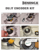
ENCODER WIRING
In case the motor is with Encoder and one wished to connect it to the control unit, carry out the connections indicated in Fig.2, in
this case the SWO1 and SWO2 inputs may not be used as Limit switch inputs.
It is not possible to use the Encoder and the closure Limit switch simultaneously.
Leave SWC1 and SWC2 shorted.
TO CHECK CONNECTIONS
1) Cut-off power supply.
2) Manually release the wings, move them to approx. half-stroke and lock them again.
3) Reset power supply.
4) Send a step-by-step control signal by pressing the <-> push-button.
5) The leeaves must move in OPENING.
In case this does not happen, it is sufficient to invert among them the motor run wires. (1<>2 for M1 motor, and 3<>4 for M2
motor) and, if used, the relative Limit switch inputs (14<>15 for M1 motor, and 16<>17 for M2 motor).
PROGRAMMING
The programming of the various functions of the control unit is carried out using the LCD display on the control unit and setting the
desired values in the programming menus described below.
The parameters menu allows you to assign a numerical value to a function, in the same way as a regulating trimmer.
The logic menu allows you to activate or deactivate a function, in the same way as setting a dip-switch.
Other special functions follow the parameters and logic menus and may vary depending on the type of control unit or the software
release.
TO ACCESS PROGRAMMING:
1 – Press the button <PG>, the display goes to the first menu, Parameters “PAR”.
2 – With the <+> or <-> button, select the menu you want (PAR>LOG>RAD>NMAN>MACI>RES>AUTO>CODE).
3- Press the button <PG>, the display shows the first function available on the menu.
4 - With the <+> or <-> button, select the function you want.
5 - Press the button <PG>, the display shows the value currently set for the function selected.
6 - With the <+> or <-> button, select the value you intend to assign to the function.
7 - Press the button <PG>, the display shows the signal “PRG” which indicates that programming has been completed.
NOTES:
Simultaneously pressing <+> and <-> from inside a function menu allows you to return to the previous menu without making any
changes. Hold down the <+> key or the <-> key to accelerate the increase/decrease of the values.
After waiting 120s the control unit quits programming mode and switches off the display.
When the board is switched on, the software version is displayed for around 5 sec
Hold down the <+> key or the <-> key to accelerate the increase/decrease of the values.

17
PARAMETERS, LOGIC AND SPECIAL FUNCTIONS
The tables below describe the individual functions available in the control unit.
PARAMETERS (PAR)
MENU FUNCTION
MIN-MAX-(Default)
MEMO
TCA
Automatic closing time. Active only with logic “TCA”=ON.
At the end of the set time the control unit orders a closing manoeuvre.
1-240-(40s)
TM1
Operating time, motor 1. The operating time is adjusted at normal speed during
motor 1 opening and closing phases. See Paragraph “Adjustment of the gate leaf
speed”.
By setting the value to 0, the operation is performed with around 2 seconds of
pick-up and then the movement is carried on at reduced speed for the entire
stroke. In the motors with encoder, the value is expressed in percentage. In mo-
tors without encoder the value is expressed in seconds.
0-99-(5)
TM2
Operating time, motor 2. The operating time is adjusted at normal speed during
motor 2 opening and closing phases. See Paragraph “Adjustment of the gate leaf
speed”.
By setting the value to 0, the operation is performed with around 2 seconds of
pick-up and then the movement is carried on at reduced speed for the entire
stroke. In the motors with encoder, the value is expressed in percentage. In mo-
tors without encoder the value is expressed in seconds.
0-99-(5)
Tped
Adjusts the motor 1 opening percentage (pedestrian function).
With Encoder equipped motors the value is expressed in a percentage (99% mean
complete opening cycle).
With the motors without Encoder or electrical Limit switch, the value is expressed
in seconds. In the motors with encoder, the value is expressed in percentage. In
motors without encoder the value is expressed in seconds.
1-99 (50)
PMo1
The anti-crash device* (amperometric sensor) operation is adjusted in the open-
ing phase, at normal speed - Motor 1.
1-99-(50%)**
PMC1
The anti-crash device* (amperometric sensor) operation is adjusted in the closing
phase, at normal speed - Motor 1.
1-99-(50%)**
PMo2
The anti-crash device* (amperometric sensor) operation is adjusted in the open-
ing phase, at normal speed - Motor 2.
1-99-(50%)**
PMc2
The anti-crash device* (amperometric sensor) operation is adjusted in the closing
phase, at normal speed - Motor 2.
1-99-(50%)**
TDMo
Mot.2 opening delay time.
Regulates the delay time of motor 2 on opening with respect to motor 1
0-15-(2s)
TDMC
Mot.1 closing delay time
Regulates the delay time of motor 1 on closing with respect to motor 2
0-40-(3s)
TLS
SERL contact activation time (Service light) 29/30 terminals.
At each manoeuvre the contact closes for the set time.
See Figure 4 connection scheme.
1-240-(60s)
TLOc
Electric lock activation time. The value is expressed in 1/10s (0=0s - 50=5s) 0-50 (5=0,5s)
SLD1
Adjusts motor 1 speed during slowing phases.
This value is expressed in percentage.
30-70 (50%)
SLD2
Adjusts motor 2 speed during slowing phases.
This value is expressed in percentage.
30-70 (50%)
SpD1
Adjusts motor 1 speed during normal speed phase.
Value expressed in percentage.
30-99 (99%)
SpD2
Adjusts motor 2 speed during normal speed phase.
Value expressed in percentage.
30-99 (99%)
Pso1
The anti-crash device* (amperometric sensor) operation is adjusted in the open-
ing phase, at reduced speed - Motor 1.
1-99-(20%)**
Psc1
The anti-crash device* (amperometric sensor) operation is adjusted in the closing
phase, at reduced speed - Motor 1.
1-99-(20%)**
Pso2
The anti-crash device* (amperometric sensor) operation is adjusted in the open-
ing phase, at reduced speed - Motor 2.
1-99-(20%)**
Psc2
The anti-crash device* (amperometric sensor) operation is adjusted in the closing
phase, at reduced speed - Motor 2.
1-99-(20%)**

18
SeaU
The intervention threshold of the anti-crashing device (Encoder) during the phase
at normal speed is adjusted.*
0:Off-1:minimum sensitivity - 99: maximum sensitivity
0-99-(0%)
SEAR
The intervention threshold of the anti-crashing device (Encoder) during braking
is adjusted *.
0:Off-1:minimum sensitivity - 99: maximum sensitivity
0-99-(0%)
tinc
This parameter is enabled only for motors equipped with Encoder.
The encoder inhibition is regulated near the opening and closing mechanical
stoppers.
1: minimum distance – 250: maximum distance
1-250-(250)
* WARNING:
AN INCORRECT SETTING OF THESE PARAMETERS MAY RESULT IN AN HAZARD.
COMPLY WITH REGULATIONS IN FORCE!
With motors without limit switch and/or encoder it adjusts the sensitivity of the sensor which causes arrest during
slowing phase.
** 1: minimum force/torque - 99: maximum force/torque.
The control unit is equipped with two ant-crash devices, the amperometric sensor (regulated by parameters PMO1/2-PMC1/2-
PSO1/2-PSC1/2) and the encoder (regulated by parameters SEAV and SEAR).
The sensitivity of the amperometric sensor is regulated by default through the Autoset procedure, while the encoder (with the
default set) is activated only when the gate stops completely when it hits an obstacle.
The use of one system at a time is recommended, giving preference to the amperometric sensor, which has a lower response
time.
LOGIC (LOG)
MENU FUNCTION
ON-OFF-(Default)
MEMO
TCA
Enables or disables automatic closing
On: automatic closing enabled
Off: automatic closing disabled
(ON)
IbL
Enables or disables condominium function.
On: condominium function enabled. The step-by-step impulse or transmitter
impulse has no effect during the opening phase.
Off: condominium function disabled.
(OFF)
ibca
The multi-flat function is enabled or disabled during the TCA counting.
On: the bloc of flat function is enabled. The Step-by-Step signal or the transmitter
signal has no effect during the TCA counting.
Off: the bloc of flat function is disabled.
(OFF)
SCL
Enables or disables rapid closing
On: rapid closure is enabled. With open gate, or in the opening phase, the
activation of the photocell causes the automatic closure 3sec after the total
opening of the gate. It is activated only with TCA:ON
Off: rapid closing disabled.
(OFF)
PP
Selects the operating mode of the ”Step by step button” and of the transmitter.
On: Operation: OPEN > CLOSE > OPEN >
Off: Operation: OPEN > STOP > CLOSE > STOP >
(OFF)
PRE
Enables or disables pre-blinking.
On: Pre-blinking enabled. Blinking is activated 3s before the motor starts.
Off: Pre-blinking disabled.
(OFF)
HAM
Enables or disables the inversion stroke function
On: Function enabled. Before each opening manoeuvre the control unit orders a
manoeuvre of 2s in the opposite direction to facilitate the release of the electric
lock.
Off: Function disabled.
(OFF)
Blco
Enables or disables the block function in opening.
On: Block function enabled. To use only with motors equipped with Limit switch.
After the intervention of the opening Limit switch the control unit delays arrest by
about 0.5s, so to allow a better strike of the shutter on the stop locks.
Off: Block function disabled
(OFF)
Blcc
Enables or disables the block function in closing.
On: Block function enabled. To use only with motors equipped with Limit switch.
After the intervention of the opening Limit switch the control unit delays arrest by
about 0.5s, so to allow a better strike of the shutter on the stop locks.
Off: Block function disabled.
(OFF)

19
SOFT
Enables or disables start at decreased speed.
On: Executes start ups at decreased speed for 2 seconds to then shift to normal
speed.
Off: Start at decreased speed not active.
(OFF)
LTCA
Selects the operating mode of the blinking light during the time TCA
On: Blinking light on during TCA
Off: Blinking light off during TCA
(OFF)
htr
Enabled or disables HOLD-TO-RUN function
On: HOLD-TO-RUN function.
The pressure of the OPENS/CLOSES button must be maintained throughout the
entire manoeuvre. The opening of the STOP input stops the motor. All the safety
inputs are deactivated, except for the Limit switch inputs /SW01/SW02/SWC1/
SWC2).
Off: Automatic/semiautomatic function
(OFF)
1mot
The operating mode with 1 or 2 motors is selected:
On: The motor operation is synchronised. This function must be used in the fol-
lowing cases:
- for each single motor, connect it to M1: Terminals 1/2.
- for two synchronised motors (e.g. balancing doors), connect one motor to M1:
terminals 1/2 and the other to M2: terminals 3/4. Adjust the parameters related
to motor 1, the M2 limit switch inputs are deactivated. TDMO and TDMC must
be 0.
Off: For two non-synchronised motors, e.g. overlapping gate leaves, adjust TDMO
and TDMC on the desired values.
(OFF)
Cvar
The code programmable transmitters is enabled or disabled.
On: Radio receiver enabled only for rolling-code transmitters.
Off: Receiver enabled for rolling-code and programmable code transmitters (self-
learning and Dip Switch).
(OFF)
mloc
Selects the type of electric lock used.
On: Magnetic electric lock, normally fed at 12Vdc.
Power is cut off to the electric lock output before each opening and closing
operation.
Off: Electric lock with latch, normally not fed.
Before each opening manoeuvre power is fed at 12Vdc for the time set by the
parameter TLOC.
(OFF)
BB
Activates or deactivates the push in closing function. Only with logic SLD:ON
On: The last second of the manoeuvre in closing phase is carried out at normal
speed (disabling slowing) to favour a better hook of the electric lock.
Off: Function disabled.
(OFF)
2ch
Enables or disables the second radio channel on terminals 29/30.
On: Exit 29/30 configured with function as second radio channel.
Off: Exit 29/30 takes on function of service light (see parameter TLS).
(OFF)
TST1
Enables or disables checking of photocells on PHOT input, active both in closing
and in opening.
On: Check enabled. If the check has a negative result, no manoeuvre is com-
manded. See Fig.3 - “PHOTO TEST”.
Off: Checking of photocells disabled at each manoeuvre.
(OFF)
TST2
Enables or disables checking of photocells on PHOT inputs, active only in clos-
ing.
On: Check enabled. If the check has a negative result, no manoeuvre is com-
manded. See Fig.3 - “PHOTO TEST”.
Off: Checking of photocells disabled at each manoeuvre.
(OFF)
TSTm
Enables or disables motors check.
On: Check enabled. If the check has a negative result, no manoeuvre is com-
manded.
Off: Check disabled.
(OFF)
rem
(Enables or disables remote radiotransmitters learning, as indicated in the para-
graph “Remote transmitters learning”.
On: Remote learning enabled.
Off: Remote learning not enabled.
(OFF)

20
RADIO (RAD)
MENU FUNZIONE
PP
By selecting this function, the receiver goes in waiting (Push) for a transmitter code to assign to the step-step func-
tion.
Press the key of the transmitter to assign to this function.
If the code is valid, it is memorised and the message OK is displayed
If the code is not valid, the message Err is displayed
2Ch
By selecting this function, the receiver goes into waiting (Push) for a transmitter code to assign to the second radio
channel.
Press the key of the transmitter to assign to this function.
If the code is valid, it is memorised ad the OK message is displayed
If the code is not valid, the message Err is displayed.
ped
By selecting this function, the receiver goes into waiting (Push) for a transmitter code to assign to the pedestrian
opening function (see parameter TPED).
Press the key of the transmitter to assign to this function.
If the code is valid, it is memorised ad the OK message is displayed
If the code is not valid, the message Err is displayed.
CLR
By selecting this function, the receiver goes into waiting (Push) for a transmitter code to erase from the memory.
If the code is valid, it is erased and the message OK is displayed
If the code is not valid or not present in memory, the message Err is displayed
RTR
Completely erases memory of the receiver. Confirmation of the operation is requested.
By selecting this function the receiver goes into waiting (Push) for a new PGM pressure to confirm the operation.
At end of erasing the OK message is displayed
CYCLES NUMBER (Nman)
Displays the number of complete cycles (open+close) carried out by the automation.
When the <PG> button is pressed for the first time, it displays the first 4 figures, the second time it shows the last 4. Example
<PG> 0012 >>> <PG> 3456: made 123.456 cycles.
MAINTENANCE CYCLES (maci)
This function enables to activate the maintenance request notice after a number of manoeuvres determined by the installer.
To activate and select the number of manoeuvres, proceed as follows:
Press button <PG>, the display will show OFF, which indicated that the function is disabled (default value).
With the buttons <+> and <-> select one of the numeric values proposed (from OFF to 100). The values are intended as hundreds
of cycles of manoeuvres (for example: the value 50 indicates 5000 manoeuvres).
Press the OK button to activate the function. The display will show the message PROG.
The maintenance request is indicated to the user by keeping the indicator lamp lit up for other 10 sec after the conclusion of the
opening or closing operation.
RESET (RES)
RESET of the control unit. ATTENTION!: Returns the control unit to the default values.
Pressing the <PG> button for the first time causes blinking of the letters RES, pressing the <PG> button again resets the control
unit. Note: The transmitters are not erased from the receiver nor is the access password.
All the logics and all the parameters are brought back to default values, it is therefore necessary to repeat the autoset proce-
dure.
AUTOSET (AUTO)
This function is used to set the optimal operating values of the automatic system and, at the end of the procedure, the LAG, OP-
ERATING TIME and BRAKING parameter are adjusted.
To carry out autoset, proceed as follows:
a) Ascertain that no obstacles of any nature are present in the manoeuvre area, if necessary, block off the area in order to prevent
access from people, animals, vehicles, etc.
During autoset phase, the anti-crushing function is not active.
b) Select the AUTO function and press OK.
c) Select with the <+> or <-> button the submenu, NOLS, LSW or ENC based on the presence of Limit switch and/or encoder:
NOLS: if the motor is without Limit switch and encoder
LSW: if the motor is equipped with Limit switch and without encoder
ENC: if the motor is equipped with encoder and without Limit switch
d) once selected press OK to begin the autoset phase.
The control unit carries out a series of manoeuvres for learning of the run of the leves and for parameter configuration.
Initially both the leaves are brought to opening position, then after some opening and closing manoeuvres at different speeds, of
one or both the shutters, the control unit displays the message OK. In case the operation has no positive result, the message ERR
is displayed. Repeat the operation after re-checking the wiring and the eventual presence of obstacles.
In case parametersTM1/TM2 or the speed are changed, repeat the autoset procedure.
During the manoeuvres the display will show some abbreviations: OPM1/OPM2 during opening of the motor 1 or 2 and CLM1/
CLM2 during closing of motor 1 or 2.

21
PROTECTION CODE (CODE)
It allows to type in an access protection code to the programming of the control unit.
A four-character alphanumeric code can be typed in by using the numbers from 0 to 9 and the letters A-B-C-D-E-F.
The default value is 0000 (four zeros) and shows the absence of a protection code.
While typing in the code, this operation can be cancelled at any moment by pressing keys + and – simultaneously. Once the pass-
word is typed in, it is possible to act on the control unit by entering and exiting the programming mode for around 10 minutes in
order to allow adjustments and tests on functions.
By replacing the 0000 code with any other code, the protection of the control unit is enabled, thus preventing the access to any
other menu. If a protection code is to be typed in, proceed as follows:
- select the Code menu and press OK.
- the code 0000 is shown, also in the case a protection code has been previously typed in.
- the value of the flashing character can be changed with keys + and -.
- press OK to confirm the flashing character, then confirm the following one.
- after typing in the 4 characters, a confirmation message “CONF” appears.
- after a few seconds, the code 0000 appears again
- the previously stored protection code must be reconfirmed in order to avoid any accidental typing in.
If the code corresponds to the previous one, a confirmation message “OK” appears.
The control unit automatically exits the programming phase. To gain access to the Menus again, the stored protection code must
be typed in.
IMPORTANT: TAKE NOTE of the protection code and KEEP IT IN A SAFE PLACE for future maintenance operations.
To remove a code from a protected control unit it is necessary to enter into programming with the password
and bring the code back to the 0000 default value.
IF YOU LOOSE THE CODE, PLEASE CONTACT THE AUTHORISED SERVICE CENTER FOR THE TOTAL RESET OF THE
CONTROL UNIT.
HOW TO ADJUST THE GATE SPEED
The duration of the movement at regular speed and therefore the duration of braking can be preset through parameters TM1 and
TM2.
If the motor is equipped with Encoder:
- Carry out an Autotest for the self-learning of values.
- Preset parameters TM1/TM2, taking account that they indicate the percentage value of stroke at regular speed.
- Preset the other parameters for speed and torque in compliance with the type of installation and regulations in force.
If the motor is not equipped with Encoder:
- Carry out an Autotest for the self-learning of values, and check duration of the opening and closing operation.
- Preset the value read on TM1/TM2 parameter, deducting the desired braking time (for example: a 25sec total opening and a 5 sec
braking is required: preset TM1/TM2 on 20sec).
- Preset the other parameters for speed and torque in compliance with the type of installation and regulations in force.
TRANSMITTERS REMOTE LEARNING
If an already memorised transmitter is available in the receiver it is possible to carry out remote radio learning (without needing to
access the control unit).
IMPORTANT: The procedure must be carried out with leaves in opening during TCA pause or with an open gate if the TCA
logic is OFF. The REM logic must be ON.
Proceed as follows:
1 Press the hidden key of the transmitter which is already memorised.
2 Press, within 5s, the key of the corresponding transmitter which is already memorised to associate to the new transmitter. The
flashing light will turn on.
3 Press within 10s the hidden key of the new transmitter.
4 Press, within 5s, the key of the new transmitter to associate to the channel chosen at point 2. The flashing light will turn off.
5 The receiver memorised the new transmitter and immediately exits from programming.
FUSES
F1: Accessory power supply safety fuse.
F2: General safety fuse
EMERGENCY BATTERY
An optional accessory is available for control unit power supply in case of absence of power.
The kit is made up of a battery charging board and two 12V rechargeable batteries, fixing clamps, screws and wiring.
For further information, refer to the instructions supplied with the accessory.

22
DIAGNOSTICS
PHOT
SWC1
STOP
SWO1 SWO2
SWC2
PHOT-C
DAS
P.P. PED OPEN CLOSE
One segment of the display is linked to each input. In the event of failure it switches on
according to the following scheme.
N.C. inputs are represented by the vertical segments. N.O. inputs are represented by
the horizontal segments.
The control unit sees the message AMP1 or AMP2 in case of anti-crushing ammeter
sensor intervention.
ERROR MESSAGES
Some messages that are displayed in case of function anomalies are listed as follows:
Amp1
Obstacle error motor 1/anti-crushing Check presence of obstacles on motor 1 leaf run
Amp2
Obstacle error motor 2/anti-crushing Check presence of obstacles on motor 2 leaf run
ENC1
Error, encoder 1/detection of the obstacle
Check the correct connection of motor 1 encoder to the control unit, that
no obstacles are present along the gate stoke and the encoder operates
correctly.
ENC2
Error, encoder 2/detection of the obstacle
Check the correct connection of motor 2 encoder to the control unit, that
no obstacles are present along the gate stoke and the encoder operates
correctly.
Err1
Motor 1 circuit checking error Check motor 1 connections
Err2
Motor 2 circuit checking error Check motor 2 connections
Err3
error/fault power circuit Request technical assistance and eventually replace control unit.
Err4
PHOTA photocell checking error
Check connections, PHOT A photocell alignment or presence of obsta-
cles.
Err5
PHOTC photocell checking error
Check connections, PHOTC photocell alignment or presence of obsta-
cles.
Err6
Error edge active (during autoset) In autoset phase, the safety edge has intervened.
Err7
Error active stop (during autoset) In autoset phase, the STOP input has intervened.
Err8
Error active input (during autoset) In autoset phase a PP/Open/Close input has intervened.
thrm
Motor thermal protection intervention
Wait for motor cooling, in case reset does not take place, motor replace-
ment may be necessary
WASTE DISPOSAL
If the product must be dismantled, it must be disposed according to regulations in force regarding the differentiated waste disposal
and the recycling of components (metals, plastics, electric cables, etc..). For this operation it is advisable to call your installer or a
specialised company.

1SFNFSFMFBMFUUFTVJmBODIJQFSTHBO
DJBSFMFEVFNBTDIFSFDPQSJWJUJ
3JNVPWFSFMFEVFWJUJTVMMBUPEJBQFSUV
SBEFTJEFSBUP
"MMFOUBSF MF EVF WJUJ DPO GVO[JPOF EJ
DFSOJFSBTFO[BSJNVPWFSMFJONPEPEB
DPOTFOUJSFMBQFSUVSBEFMDPQFSDIJP
1SFTTUIFUBCTPOUIFTJEFTUPSFMFBTF
UIFUXPNBTLTUIBUDPWFSUIFTDSFXT
3FNPWFUIFUXPTDSFXTPOUIFEFTJSFE
PQFOJOHTJEF
4MBDLFO UIF UXP TDSFXT UIBU BDU BT B
IJOHFXJUIPVUSFNPWJOHUIFNTPBTUP
BMMPXPQFOJOHPGUIFDPWFS
"VG EJF TFJUMJDIFO -BTDIFO ESàDLFO
TPEBTTEJFCFJEFO4DISBVCFOCMFOEFO
CFGSFJUXFSEFO
%JF CFJEFO 4DISBVCFO BO EFS HF
XàOTDIUFO½GGOVOHTTFJUFBVTCBVFO
;VMFU[U EJF CFJEFO BMT 4DIBSOJFS EJF
OFOEFO4DISBVCFOMPDLFSOBCFSOJDIU
BVTCBVFO EBNJU EFS %FDLFM HFÚGGOFU
XFSEFOLBOO
1SFTTFSMFTEFVYBJMFUUFTMBUÏSBMFTQPVS
EÏDSPDIFSMFTEFVYDBDIFWJT
&OMFWFS MFT EFVY WJT TVS MF DÙUÏ
EPVWFSUVSFEÏTJSÏ
%FTTFSSFSMFTEFVYWJTGBJTBOUGPODUJPO
EFDIBSOJÒSFTBOTMFTFOMFWFSEFNB
OJÒSF Ë QFSNFUUSF MPVWFSUVSF EV DPV
WFSDMF
1SFTJPOBS MBT BMFUBT FO MPT MBEPT QBSB
EFTFOHBODIBSMBTEPT UBQBT DVCSFUPS
OJMMPT
&YUSBFS MPT EPT UPSOJMMPT EFM MBEP EF
BQFSUVSBEFTFBEP
"nPKBSMPTEPTUPSOJMMPTDPOGVODJØOEF
CJTBHSB TJO FYUSBFSMPT B mO EF QPEFS
BCSJSMBUBQB
/BDJTOįİ CPD[OF LMBQLJ X DFMV PEIB
D[FOJB EXØDI NBTFL OBLSZXBKįDZDI
ŔSVCZ
8ZDJįHOįİEXJFŔSVCZQPXZCSBOFKEP
PUXJFSBOJBTUSPOJF
1PMV[PXBİ EXJF ŔSVCZ CMPLVKįDF CF[
XZDJįHBOJB JDI X TQPTØC VNPŤMJ
XJBKįDZPUXBSDJFOBLSZXLJ
"650."5*4.*#&/*/$®4Q"7JB$BQJUFMMP4BOESJHP7*5FMSB'BY
/