
MATRIX
MATRIX-RE
CP.BULL
CP.BULL-RI
L8542124
07/2010 rev 5
UNIONE NAZIONALE COSTRUTTORI
AUTOMATISMI PER CANCELLI, PORTE
SERRANDE ED AFFINI

MATRIX / MATRIX-RE / CP.BULL / CP.BULL-RI
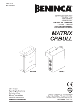
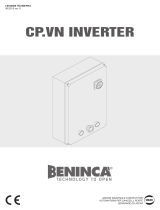
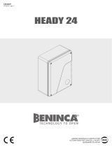
J1 DAS
Open
DAS N.C.
J1 DAS
Close
DAS 8K2
45
67
RX
2 CH.
SHIELD
ANT
LN
Service
Light
230V
SCA 24Vac
3W max
SERL:On
SERL:Off
230V: F5A
115V: F10A
230V: T0,315
115V: T0,5
230V: T1A
115V: T1A
Relè 24Vac
A
B
C
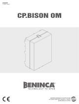
ENCODER
MATRIX
ENCODER
CP.BULL
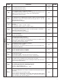
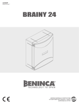
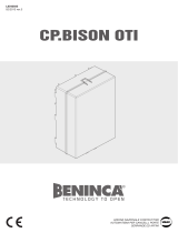
MATRIX > BULL10M SC/15M SC
Collegamento Encoder - Encoder Connection - Anschluss Encoder
Branchement Encodeur - Conexión Encoder - Połączenia Enkoderem
3x0,5mm
2
max 10m
A Signal Bianco/White/Weiss/Blanc/Blanco/Biały
B +5V Marrone/Brown/Braun/Marron/Marrón/Brązowy
C GND Verde/Green/Grüne/Verte/Verde/Zielony

3
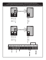
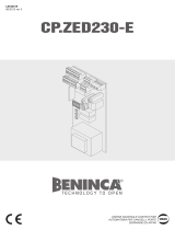
24Vac 24Vac
COM
NC
RX1 TX1
24Vac 24Vac
COM
NC
RX2 TX2
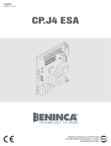
Phtoto TEST - 13
24Vac - 8
24Vac - 8
24Vac - 9
COM - 19
PHOT C - 24
Phtoto TEST - 13
24Vac - 8
24Vac - 8
24Vac - 9
COM - 19
PHOT O - 21
Collegamento dispositivi di sicurezza verificati / Connection of tested safety devices
Anschluss geprüfter Sicherheitsvorrichtungen / Branchement dispositifs de sécurité vérifiés
Conexión de los dispositivos de seguridad verificados / Połączenia sprawdzanych urządzeń bezpieczeństwa

11
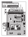
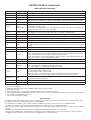
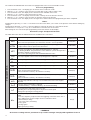
MATRIX/CP.BULL Control Unit
INPUT/OUTPUT FUNCTIONS
Terminal No. Function Description
1-2 Power supply Input, 230Vac 50Hz (1-Phase/2-Neutral)
3 GND Connection to ground (compulsory)
4-5 Aerial Connection of the insertable radio receiver card (4-signal/5-display).
6-7 RX 2° Ch
Output, second radio channel of the receiver. N.O. voltage-free contact.
This output is not available in CP.BULL-RI and MATRIX control units with built-in receiver.
8-9 24Vac Output: power supply of accessories, 24Vac/500mA max.
10-11
SCA o
Service light
Normally Open (N.O.) free contact. Configuration like SCA (open gate warning LED) or timed
service light (see SERL Logic).
In CP.BULL-RI and MATRIX control units with built-in receiver, this contact can be preset as
output of second radio contact (see 2ChLogic).
12-13 PHOTO TEST
N.O. free contact. It is used to power photocell transmitters in TEST operating mode.
See diagram “Connection of tested safety devices” and TST1 and TST2 Logic.
14 COM Common for control inputs.
15 OPEN Input, OPEN push-button (N.O. contact).
16 CLOSE Input, CLOSE push-button (N.O. contact)
17 Step-by-Step Input, step-by-step push-button (N.O. contact)
18 PED
Input, pedestrian push-button (N.O. contact). It controls the partial opening. Configuration is
through parameter TPED. When TCA time has elapsed (if activated) a closure control signal
is sent.
19 COM Common, for limit switches and safety devices
20 STOP Input, STOP push-button (N.C. contact)
21 PHOT O
Input, (N.C. contact) for safety devices (e.g. photocells).
In the closing phase: the contact opening causes the motor stop. Common: when the photo-
cell is released, the motor inverts the movement direction (open).
In the opening phase: the contact opening causes the motor stop. When the photocell is
released, the motor re-starts the opening operation.
22 SWO Input, OPEN limit switch (N.C. contact)
23 SWC Input, CLOSE limit switch (N.C. contact)
24 PHOT C
Input (N.C. contact) for safety devices (e.g. photocells).
In the closing phase: Configuration through PHTC Logic.
In the opening phase: Configuration through PHTC Logic.
25-26 DAS
Input, safety edge
Resistive edge: “DAS” Jumper closed
Mechanical edge: “DAS” Jumper open
When the edge is activated, the gate movement is stopped and reversed for about 3s.
If the edge is not in use: “DAS” Jumper open, 25-26 terminals are short-circuited.
27-28-29 Motor
Connection of motor 230Vac - single-phase:
27-Phase/28-Common/29-Phase
27-30 Capacitor Connection of capacitor
31-32 Blinker Connection of blinker, 230Vac 40W max.
To check connections:
1) Cut-off power supply.
2) Manually release the wing, move it to approx. half-stroke and lock it again.
3) Reset power supply.
4) Send a step-by-step control signal by pressing the button or the remote control key.
5) The wing should start an opening movement. If this is not the case, invert the movement wires (27< >29) of the motor and the
limit switch wires SWO-SWC (22< >23).
6) Cut-off and restore power supply.
Programming
The programming of the various functions of the control unit is carried out using the LCD display on the control unit and setting
the desired values in the programming menus described below.
The parameters menu allows you to assign a numerical value to a function, in the same way as a regulating trimmer.
The logic menu allows you to activate or deactivate a function, in the same way as setting a dip-switch.
Other special functions follow the parameters and logic menus and may vary depending on the type of control unit or the software
release.
The CP.BULL-RI and MATRIX control units are equipped with a built-in radio module to receive both
fixed code and variable code control signals with a frequency of 433.92MHz, able to store up to 64 different codes in memory.
The RADIO menu and the 2Ch and CVAR logic are available in these control units only.

12
The CP.BULL and MATRIX-RE control units are equipped with connector for extractable receiver.
To access programming:
1 Press the button <PG>, the display goes to the first menu, Parameters “PAR”.
2 With the <+> or <-> button, select the menu you want (PAR>>LOG>>RADIO>>NMAN>>RES)
3 Press the button <PG>, the display shows the first function available on the menu.
4 With the <+> or <-> button, select the function you want.
5 Press the button <PG>, the display shows the value currently set for the function selected.
6 With the <+> or <-> button, select the value you intend to assign to the function.
7 Press the button <PG>, the display shows the signal “PRG” which indicates that programming has been completed.
Notes:
Simultaneously pressing <+> and <-> from inside a function menu allows you to return to the previous menu without making any
changes.
Simultaneously pressing <+> and <-> when the display is switched off shows the card software release.
Hold down the <+> key or the <-> key to accelerate the increase/decrease of the values.
After waiting 30s the control unit quits programming mode and switches off the display.
Parameters, Logic and Special Functions
The tables below describe the individual functions available in the control unit.
MENU FUNCTION
Settable values
MIN-MAX-(Default)
MEMO
PARAMETERS
TCA
Automatic closure time. It is activated only with “TCA”=ON logic.
At the end of the preset time, the control unit controls a closure operation.
1-240-(40s)
Tped
The passage left open by the gate leaf during the partial opening (pedestrian)
is adjusted.This value is expressed in decimetres.
2-100-(5dm)
Tsm
The area covered by the gate during the braking phase is adjusted.
0 = braking disabled. The performance of the automatic system during the first
operations depends on the ENC logic.
See section “Operating mode with enabled/disabled Encoder”.
0-100-(0%)
PMo
The torque applied to the motor in the opening phase is adjusted.* 1-99-(50%)
PMC
The torque applied to the motor in the closing phase is adjusted *. 1-99-(50%)
Pso
The torque applied to the motor during braking in the closing phase is adjusted.*
1-99-(50%)
Psc
The torque applied to the motor during braking in the opening phase is adjusted *
1-99-(50%)
SeaU
The intervention threshold of the anti-crashing device (Encoder) during the
phase at normal speed is adjusted.*
0:Off-1:maximum sensitivity - 99: minimum sensitivity
0-99-(0%)
SEAR
The intervention threshold of the anti-crashing device (Encoder) during braking
is adjusted *.
0:Off-1:maximum sensitivity - 99: minimum sensitivity
0-99-(0%)
TLS
Activated only with SERL:ON Logic. The activation time of the service light is
adjusted.
1-240-(60s)
Ibra
The force of the motor brake is adjusted.
0: disabled braking - 1:minimum braking - 99: maximum braking
0-99-(50%)
TM
It is activated only with SERL logics EN : OFF.
Operating time. The operating time is adjusted at normal speed
during motor opening and closing phases.
1-250-(90s)
BLC
Motor stop delay on limit switch. It is activated only with enabled braking
(TSM).
The motor stop delay is adjusted after the triggering of the limit switch. Use a
value calibrated on the gate weight. Use these indicative values:
0 deactivated (no delay)
1 very heavy gates (short delay)
2 heavy gates
3 average gates
4 light gates (longer delay)
0-4 (0)
* WARNING:
An incorrect setting of these parameters may result in a danger. Comply with regulations in force!

13
MENU FUNCTION
Settable values
ON-OFF-(Default)
MEMO
LOGIC
TCA
The automatic closure is enabled or disabled
On: enabled automatic closure
Off: disabled automatic closure
(ON)
IbL
The multi-flat function is enabled or disabled.
On: enabled multi-flat function. The P.P. (Step-by-step) impulse or the
impulse of the transmitter have no effect in the opening phase.
Off: disabled multi-flat function.
(OFF)
SCL
The rapid closure is enabled or disabled
On: rapid closure is enabled. When the gate is open or moving, the photo-
cell activation causes the automatic closure of the gate after 3 s. It is acti-
vated only with TCA:ON
Off: rapid closure is disabled.
(OFF)
PP
The operating mode of “P.P. Push button” and of the transmitter are
selected.
On: Operation : OPEN > CLOSE > OPEN >
Off: Operation: OPEN > STOP > CLOSE > STOP >
(OFF)
PRE
Forewarning flashing light enabled or disabled.
On: enabled forewarning flashing light. The flashing light is activated 3 s
before the starting of the motor.
Off: disabled forewarning flashing light.
(OFF)
LTCA
During the TCA time, the blinker is enabled or disabled.
On: Activated blinker.
Off: De-activated blinker.
(OFF)
CLOC
The OPEN input mode is selected
On: OPEN input with WATCH function.
To be used for the connection of timed opening/closing. (CLOSED contact
- open gate. OPEN contact - normal operation).
Off: OPEN input with OPEN function.
(OFF)
htr
The Operator function is enabled or disabled.
On: Operator function enabled.
During operation, the OPEN/CLOSE push-buttons must be kept pressed.
Off: Automatic operation.
(OFF)
IBCA
During the TCA phase, the PP and PED controls are enabled or disabled.
On: PP and PED controls are disabled.
Off: PP and PED controls are enabled.
(OFF)
ENC
The Encoder is enabled or disabled. See section “Operating mode with ena-
bled/disabled Encoder”
On: Encoder enabled – The anti-crash sensor is activated.
Off: Encoder disabled – The anti-crash sensor is deactivated.
(ON)
Cvar
The code programmable transmitters is enabled or disabled.
On: Radio receiver enabled only for rolling-code transmitters.
Off: Receiver enabled for rolling-code and programmable code transmitters
(self-learning and Dip Switch).
OFF
2ch
The second radio channel is enabled or disabled on terminals 10/11 (it can
be used only for control units with built-in receiver).
On: 10/11 output, preset as second radio channel.
The SERL logic should be OFF.
Off: 10/11 output, preset by the SERL Logic.
(OFF)
serL
The service light function to output 10-11 is enabled or disabled.
On: At every operation, the contact is closed for the time preset with TLS
parameter
Use the auxiliary relay to control the light.
Off: the output is provided with SCA function, open gate LED: open contact
with closed gate - flashing light in closing phase - closed contact in opening
phase and open gate. See wire diagram.
(OFF)

14
MENU FUNCTION
Settable values
ON-OFF-(Default)
MEMO
LOGIC
TST1
The test of photocells to PHOT O input is enabled or disabled.
On: Test is enabled. If the test is negative, no operation is performed.
Off: Test is disabled.
(OFF)
TST2
The test of photocells to PHOT C input is enabled or disabled.
On: Test is enabled. If the test is negative, no operation is performed.
Off: Test is disabled.
(OFF)
PHTC
The operating mode of the PHOT C input is selected.
On: PHOT C input is activated in both opening and closing phases.
In the opening phase: the contact opening causes the motor stop. When the
photocell is released, the motor restarts in the opening phase.
In closing phase: the contact opening causes the motor stop. When the
photocell is released, the motor inverts the movement direction (open).
Off: The PHOT C input is activated in the closing phase only.
In the closing phase: the contact opening causes the motor stop and the
immediate reversion of the operation direction (open).
(OFF)
MENU FUNCTION
RADIO
PP
By selecting this function, the receiver awaits (Push) for a transmitter code to be assigned to the step-by-step
function.
Press the transmitter key to be assigned to this function.
If the code is valid, it is stored in memory and OK appears.
If the code is not valid, the wording Err is displayed.
2ch
By selecting this function, the receiver awaits (Push) for a transmitter code to be assigned to the second radio
channel.
Press the transmitter key to be assigned to this function.
If the code is valid, it is stored in memory and OK appears.
If the code is not valid, the wording Err is displayed.
CLr
By selecting this function, the receiver awaits (Push) for a transmitter code to be erased from memory.
If the code is valid, it is erase and OK appears.
If the code is not valid or is not in memory, the wording Err is displayed.
RTR
Completely erase the receiver memory. Confirmation of operation is required.
MENU FUNCTION
NMAN
Displays the number of complete cycles (open+close) carried out by the automation.
When the <PG> button is pressed for the first time, it displays the first 4 figures, the second time it shows the
last 4. Example <PG> 0012 >>> <PG> 3456: made 123.456 cycles.
RES
RESET of the control unit. ATTENTION!: Returns the control unit to the default values.
Pressing the <PG> button for the first time causes blinking of the letters RES, pressing the <PG> button again
resets the control unit.
Note: The transmitter codes are not erased from the receiver.
Operating mode with enabled/disabled Encoder
ENC LOGICS =ON: anti-crash sensor activated.
If an obstacle is detected, the control unit will control the movement stop and a movement reversion of about 3s.
Adjust sensitiveness through parameters SEAV and SEAR, in compliance with regulations in force.
An accurate adjustment of the motor brake (IBRA parameter) can help to comply with safety regulations in force.
Braking
With TSM parameter higher than 0 (activated braking), the control unit carries out braking by using the Encoder as position sensor.
The first operation is carried out at regular speed, without braking, so as to allow the control unit to learn the stroke length.
Once the stroke has been recorded, the control unit will be able to automatically manage braking phases in both opening and clos-
ing phases. The braking space can be increased or decreased through TSM parameter.
This learning phase is carried out also in case of power failure or when braking is activated (TSM parameter is modified from 0 to a
value higher than 0)
ENC LOGICS =OFF: anti-crash sensor deactivated.
Braking
With TSM parameter higher than 0 (activated braking), the control unit carries out braking by calculating the operating time.
If the first operation starts from a limit switch position, the control unit carries out a complete operation at optimal speed. Braking in
opening and closing phases will start with the following operation. If the operation starts from an intermediate position, the control
unit reaches the limit switch position at normal speed. An operation will be carried out at regular speed until the previous intermedi-
ate position is reached, and then the system will continue its stroke at reduced speed until the limit switch is reached.
The control unit will carry out braking in both opening and closing phases only after this procedure. Braking space can be increased
or decreased through TSM parameter.

15
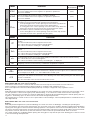
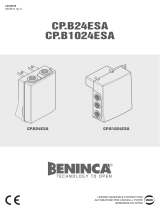
Diagnostics
In the event of malfunctions, by pressing key + or - the status of all inputs (limit switches, control and safety) can be displayed. One
segment of the display is linked to each input. In the event of failure it switches on according to the following scheme.
PHOT 0
SWC
STOP
SWO
PHOT C
DAS
P.P. PED OPEN CLOSE
Error messages
The control unit checks the correct operation of the safety devices. In case of failure, the following messages may appear on the
display:
ERR1 Error, check photocells at PHOT O input.
ERR2 Error, check photocells at PHOT C input.
ERR3 Error, ENCODER/ check fuse F3
ERR4 Error, TRIAC
Fuses
F1 Protection fuse of transformer
F2 Output protection fuse of accessories and signals
F3 Output protection fuse for motor and blinker
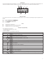
Example of programming
Let us suppose it is necessary to:
- set an automatic closing time (TCA) of 100s
- activate pre-blinking
Perform the operations described below step by step:
Step Press Display Notes
1
PAR
First menu
2
TCA
First function of the first menu
3
040
Value currently set for the function selected
4
100
Set the desired value with the <+> and <-> keys
5
PRG
The value is programmed
TCA
When programming has been made, the display goes to the function just set
6
PAR
Press <+> and <-> simultaneously to go to the higher menu
7
Log
Second menu
8
TCA
First function of the second menu
9
Pre
Press <-> several times to select PRE logic
10
OFF
Value currently set for the function selected
11
ON
Set the desired value with the <+> and <-> keys
12
PRG
The value is programmed
Pre
When programming has been made, the display goes to the function just set
13
PAR
Press <+> and <-> simultaneously to go to the higher menu and quit programming or wait
30s.
-
 1
1
-
 2
2
-
 3
3
-
 4
4
-
 5
5
-
 6
6
-
 7
7
-
 8
8


Ask a question and I''ll find the answer in the document
Finding information in a document is now easier with AI
Related papers
-
 Beninca MATRIX and CP.BULL Owner's manual
-
 Beninca Matrix Operating Instructions Manual
-
 Beninca CP.Bison Operating instructions
-
 Beninca CPZED230-E User guide
-
 Beninca CPVN Invertor User guide
-
 Beninca Brainy24 Owner's manual
-
 Beninca CP.J4 ESA User manual
-
 Beninca CPB24ESA Operating instructions
-
 Beninca Heady 24vHeady 24v User guide
-
 Beninca CP.BISON OTI User guide


