Page is loading ...

User’s Manual Pub. 0300128-04 Rev. A

ii SLC 500™ Isolated Analog Output Modules
User’s Manual Pub. 0300128-04 Rev. A
Important Notes
1. Please read all the information in this owner’s guide before installing the
product.
2. The information in this owner's guide applies to hardware Series A and
firmware version 1.00 or later.
3. This guide assumes that the reader has a full working knowledge of the
relevant processor.
Notice
The products and services described in this owner's guide are useful in a wide
variety of applications. Therefore, the user and others responsible for applying
the products and services described herein are responsible for determining their
acceptability for each application. While efforts have been made to provide
accurate information within this owner's guide, Spectrum Controls, Inc. assumes
no responsibility for the accuracy, completeness, or usefulness of the information
herein.
Under no circumstances will Spectrum Controls, Inc. be responsible or liable for
any damages or losses, including indirect or consequential damages or losses,
arising out of either the use of any information within this owner's guide or the
use of any product or service referenced herein.
No patent liability is assumed by Spectrum Controls, Inc. with respect to the use
of any of the information, products, circuits, programming, or services referenced
herein.
The information in this owner's guide is subject to change without notice.
Limited Warranty
Spectrum Controls, Inc. warrants that its products are free from defects in
material and workmanship under normal use and service, as described in
Spectrum Controls, Inc. literature covering this product, for a period of 1 year.
The obligations of Spectrum Controls, Inc. under this warranty are limited to
replacing or repairing, at its option, at its factory or facility, any product which
shall, in the applicable period after shipment, be returned to the Spectrum
Controls, Inc. facility, transportation charges prepaid, and which after
examination is determined, to the satisfaction of Spectrum Controls, Inc., to be
thus defective.
This warranty shall not apply to any such equipment which shall have been
repaired or altered except by Spectrum Controls, Inc. or which shall have been
subject to misuse, neglect, or accident. In no case shall the liability of Spectrum
Controls, Inc. exceed the purchase price. The aforementioned provisions do not
extend the original warranty period of any product which has either been repaired
or replaced by Spectrum Controls, Inc.

User’s Manual Pub. 0300128-04 Rev. A
Table of Contents
IMPORTANT NOTES ............................................................................................................................................... II
LIMITED WARRANTY .............................................................................................................................................. II
CHAPTER 1 MODULE OVERVIEW ......................................................................................................................... 1-1
SECTION 1.1 GENERAL FEATURES AND BENEFITS ............................................................................................................. 1-1
SECTION 1.2 DETAILED SPECIFICATIONS .......................................................................................................................... 1-2
CHAPTER 2 INSTALLATION AND WIRING ............................................................................................................. 2-1
SECTION 2.1 PREVENT ELECTROSTATIC DISCHARGE .......................................................................................................... 2-2
SECTION 2.2 POWER REQUIREMENTS ............................................................................................................................ 2-3
SECTION 2.3 SETTING THE DIP SWITCH .......................................................................................................................... 2-3
SECTION 2.4 SELECTING A RACK SLOT ............................................................................................................................ 2-4
SECTION 2.5 SELECTING A LOCATION ............................................................................................................................. 2-4
SECTION 2.6 INSERTING YOUR MODULE INTO THE RACK ................................................................................................... 2-5
SECTION 2.7 WIRING YOUR MODULE ............................................................................................................................ 2-6
CHAPTER 3 CONFIGURING THE 1746SC-INO4I ..................................................................................................... 3-1
SECTION 3.1 INTRODUCTION ........................................................................................................................................ 3-1
SECTION 3.2 ABOUT COMMUNICATIONS......................................................................................................................... 3-1
SECTION 3.3 CONFIGURATION ...................................................................................................................................... 3-2
3.3.1 Channel Update Time ............................................................................................................................... 3-2
3.3.2 Temperature Calibration Time .................................................................................................................. 3-2
3.3.3 Output Mode Change Time (-INO4vi only) ................................................................................................. 3-2
3.3.4 Your Module’s Response to Slot Disabling ................................................................................................... 3-2
3.3.5 Entering Your Module’s ID Code ............................................................................................................... 3-3
3.3.6 Output Image ............................................................................................................................................ 3-4
3.3.7 Input Image ............................................................................................................................................... 3-5
3.3.8 Configuring Each Output Channel ............................................................................................................. 3-5
3.3.9 Output Channel Enable (configuration bits 0 and 8) ................................................................................ 3-6
3.3.10 Output Range (configuration bits 1–3 and 9–11) ................................................................................... 3-6
3.3.11 Data Format (configuration bits 4–6 and 12–14) ................................................................................... 3-6
3.3.12 Reset Output Or Hold Last Value On Fault (configuration bits 7 and 15) .................................................. 3-8
3.3.13 Setting the Output Data Limits (or User-Defined Scale) ......................................................................... 3-8
3.3.14 Output Data Limits.................................................................................................................................. 3-9
3.3.15 User-Defined Scale ................................................................................................................................ 3-10
3.3.16 Controlling Each Output Channel’s Signal ............................................................................................ 3-11
3.3.17 Monitoring Each Output Channel ......................................................................................................... 3-12
3.3.18 Checking Each Output Channel’s Configuration Status ........................................................................ 3-12
3.3.19 Output Data Limiting Enabled (status bit 8) ......................................................................................... 3-13
3.3.20 Operating Temperature Error (status bit 9) .......................................................................................... 3-14
3.3.21 Over-Limit Error (status bit 10) ............................................................................................................. 3-14
3.3.22 Under-Limit Error (status bit 11) ........................................................................................................... 3-14
3.3.23 Over-Range Error (status bit 12) ........................................................................................................... 3-14
3.3.24 Under-Range Error (status bit 13) ......................................................................................................... 3-14
3.3.25 Non-Fatal Channel Error (status bit 14) ................................................................................................ 3-14
3.3.26 Fatal Channel Error (status bit 15) ........................................................................................................ 3-14
CHAPTER 4 TESTING YOUR MODULE ................................................................................................................... 4-1
SECTION 4.1 INSPECTING YOUR MODULE ......................................................................................................................... 4-1
SECTION 4.2 DISCONNECTING PRIME MOVERS ................................................................................................................. 4-1
SECTION 4.3 POWERING UP ......................................................................................................................................... 4-2
SECTION 4.4 INTERPRETING THE LED INDICATORS ............................................................................................................ 4-2

iv SLC 500™ Isolated Analog Output Modules
User’s Manual Pub. 0300128-04 Rev. A
SECTION 4.5 INTERPRETING I/O ERROR CODES ............................................................................................................... 4-3
SECTION 4.6 TROUBLESHOOTING................................................................................................................................... 4-4
CHAPTER 5 MAINTAINING YOUR MODULE AND ENSURING SAFETY ................................................................... 5-1
SECTION 5.1 PREVENTIVE MAINTENANCE ........................................................................................................................ 5-1
SECTION 5.2 SAFETY CONSIDERATIONS ........................................................................................................................... 5-1
SECTION 5.3 GETTING TECHNICAL ASSISTANCE ................................................................................................................ 5-2
SECTION 5.4 DECLARATION OF CONFORMITY .................................................................................................................. 5-2

SLC 500™ Isolated Analog Output Modules v
User’s Manual Pub. 0300128-04 Rev. A
Preface
Read this preface to familiarize yourself with the rest of the manual. This preface
covers the following topics:
• Who should use this manual
• What This Manual Covers
• Related documentation
• Technical Support
• Documentation
• Conventions used in this manual
Who Should
Use This Manual
Use this guide if you design, install, program, or maintain a control system that
uses Allen-Bradley Small Logic Controllers.
You should have a basic understanding of SLC 500 products. You should also
understand electronic process control, and the ladder program instructions
required to generate the electronic signals that control your application. If you do
not, contact your local Allen-Bradley representative for the proper training before
using these products.
What This
Manual Covers
This guide covers the 1746sc-INO4i and 1746sc-INO4vi isolated analog output
modules. It contains the information you need to install, wire, use, and maintain
these modules. It also provides diagnostic and troubleshooting help should the
need arise.
Related
Documentation
The table below provides a listing of publications that contain important
information about Allen-Bradley PLC systems.
Refer to this Document Allen-Bradley
Pub. No.
SLC 500 System Overview 1747-2.30
Application Considerations for Solid
State Controls
SGI-1.1
Allen-Bradley Programmable Controller
Grounding and Wiring Guidelines
1770-4.1
Installation & Operation Manual for
Modular Hardware Style Programmable
Controllers
1747-6.2
Installation & Operation Manual for
Fixed Hardware Style Programmable
Controllers
1747-NI001
Allen-Bradley Advanced Programming
Software (APS) User Manual
1747-6.4

vi SLC 500™ Isolated Analog Output Modules
User’s Manual Pub. 0300128-04 Rev. A
Refer to this Document Allen-Bradley
Pub. No.
Allen-Bradley Advanced Programming
Software (APS) Reference Manual
1747-6.11
Getting Started Guide for Advanced
Programming Software (APS)
1747-6.3
SLC 500 Software Programmers’ Quick
Reference
ABT-1747-TSG001
Guide
Allen-Bradley HHT (Hand-Held
Terminal) User Manual
1747-NP002
Getting Started Guide for HHT (Hand-
Held Terminal)
1747-NM009
Allen-Bradley Publication Index SD499
Allen-Bradley Industrial Automation
Glossary
AG-7.1
Technical
Support
For technical support, please contact your local Rockwell Automation
TechConnect Office for all Spectrum products. Contact numbers are as follows:
• USA 1-440-646-6900
• United Kingdom 01-908-635-230
• Australia 1-800-809-929
• Mexico 001-888-365-8677
• Brazil 55-11-3618-8800
• Europe +49-211- 41553-630
or send an email to
support@spectrumcontrols.com
Documentation
If you would like a manual, you can download a free electronic version from the
Internet at www.spectrumcontrols.com
Conventions
Used in This
Manual
The following conventions are used throughout this manual:
• Bulleted lists (like this one) provide information, not procedural steps.
• Lists provide sequential steps or hierarchical information.
• Italic type is used for emphasis.
• Bold type identifies headings and sub-headings:
WARNING
Identifies information about practices or circumstances that can lead to
personal injury or death, property damage, or economic loss. These
messages help you to identify a hazard, avoid a hazard, and recognize the
consequences.

SLC 500™ Isolated Analog Output Modules vii
User’s Manual Pub. 0300128-04 Rev. A
ATTENTION
Actions ou situations risquant d’entraîner des blessures pouvant être
mortelles, des dégâts matériels ou des pertes financières. Les messages «
Attention » vous aident à identifier un danger, à éviter ce danger et en
discerner les conséquences.
NOTE
Identifies information that is critical for successful application and
understanding of the product.

viii SLC 500™ Isolated Analog Output Modules
User’s Manual Pub. 0300128-04 Rev. A

User’s Manual Pub. 0300266-04 Rev. A
Chapter 1
Module Overview
The 1746sc-INO4i provides four isolated channels of current outputs, while the
1746sc-INO4vi provides four isolated channels of current or voltage outputs (in
any combination). In both modules, the voltage and/or current ranges are
independently configurable for each channel. These modules also provide new,
advanced features to make your control systems more dependable and flexible.
Read this chapter to familiarize yourself further with your isolated analog module
(shown above). This chapter covers:
• General features and benefits.
• Detailed specifications.
Section 1.1
General Features
And Benefits
Both modules provide 750 VDC channel-to-channel isolation, which means no
electrical noise crosstalk between channels, resulting in a high, usable resolution.
They provide 750 VDC field-wiring-to-backplane isolation to protect the
processor and rack. These modules also feature onboard temperature
compensation to maintain their accuracy with fluctuating ambient temperatures,
which is important for crowded control cabinets.
These modules provide 16 bits of resolution, user-programmable range settings,
continuous temperature compensation (no field calibration), software
configuration, programmable output limits, and programmable safe states in case
of a fault.

1-2 Chapter 1: Module Overview
User’s Manual Pub. 0300128-04 Rev. A
Section 1.2
Detailed Specifications
Table 1-1. Electrical Specifications-Module
Description
Specification
Backplane Current Consumption
(maximum)
1746sc-INO4i 120 mA at 5 VDC
250 mA at 24 VDC
1746sc-INO4vi 120 mA at 5 VDC
250 mA at 24 VDC
Backplane Power Consumption
(typical)
0.6 W
Number of Channels 4 (differential, individually isolated)
I/O Chassis Location Any 1746 I/O module slot except slot 0
A/D Conversion Method Sigma-Delta
Calibration Factory calibrated
Temperature compensation once a
minute
Opto-Electrical Isolation
750 VDC channel-to-channel
750 VDC field wiring-to-backplane
Module ID Code
1746sc-INO4i
3521
1746sc-INO4vi 3519
Thermal Dissipation 4.5 W maximum
Table 1-2. Electrical Specifications-Outputs
Description
Specification
Output Current Ranges (selectable
for each channel)
4 to 20 mA
0 to 20 mA
0 to 21 mA
Output Voltage Ranges‒INO4vi
only (selectable for each channel)
-10 to +10 VDC
0 to 10 VDC
0 to 5 VDC
1 to 5 VDC
SLC Communication Formats
(selectable for each channel)
Scaled engineering units
Scaled for PID
Proportional counts
1746-INO4 format
User-defined scale

Chapter 1: Module Overview 1-3
User’s Manual Pub. 0300266-04 Rev. A
Description Specification
Output Impedance
Current Outputs
Voltage Outputs—INO4vi only
Greater than 1 Mohm
Less than 1.0 Ohm
Load Range
Current Outputs
Voltage Outputs—INO4vi only
0 to 500 Ohm
1 kohm and greater
Max. Current, Voltage Mode-
INO4vi only
10 mA
Output Step Response Time 1 ms (0-95% of full scale)
Channel Update Time (maximum)
33.7 ms for all 4 channels in parallel
Output Resolution 16-bit
Current Outputs 366 nA/count
Voltage Outputs-INO4vi only 320 µV/count
Overall Accuracy
Current Outputs
Voltage Outputs-INO4vi only
0.08% of full scale at 25 °C typical
0.15% of full scale at 60 °C
0.08% of full scale at 25 °C typical
0.35% of full scale at 60 °C
Table 1-3. Physical Specifications
Description
Specification
LED Indicators Four green channel status indicators, one
for each channel
One green module status indicator
Recommended Cable
Belden 8761 (shielded, twisted-pair) or
equivalent
Wire Size (maximum) One 12–24 AWG wire per terminal
Terminal Block Removable (supplied)
Table 1-4. Environmental Specifications
Description Specification
Operating Temperature 0 to 60 °C (32 to 140 °F)
Storage Temperature -40 to 85 °C (-40 to 185 °F)
Relative Humidity 5 to 95% non-condensing Certifications
Certifications
UL/CUL and CE
Hazardous Environment
Classifications
Class I Division 2 Groups A, B, C, D

1-4 Chapter 1: Module Overview
User’s Manual Pub. 0300128-04 Rev. A
Section 1.3 Regulatory Requirements
Compliance
Standards Industry Standards
UL Safety
UL 61010-2-201 Safety Requirements for Electrical Equipment for
Measurement, Control, and Laboratory Use - Part 2-201: Particular
Requirements for Control Equipment (NRAQ, NRAQ7)
CAN/CSA C22.2 No. 61010-1-12 (Safety Requirements for Electrical
Equipment for Measurement, Control,
and Laboratory Use – Part 1: General Requirements)
UL Hazardous
Locations
ANSI/ISA–12.12.01 Nonincendive Electrical Equipment for Use in Class I,
Division 2 Hazardous (Classified) Locations (NRAG)
CSA C22.2 No. 213-M1987 - Non-incendive Electrical Equipment for use in
Class I Division 2 Hazardous Locations - March 1987 (NRAG7)
Temp code T4 or better, Pollution degree 2, gas groups A, B, C, and D
CE EMC Directive
EN 61131-2 Programmable Controllers: Third Edition 2007-02, Clause 8,
Zones A&B
EN 61000-6-2: Generic Industrial Immunity
EN 61000-6-4: Generic Industrial Emissions
UKCA Electromagnetic Compatibility Regulations 2016
BS EN 61131-2, BS EN 61000-6-4, BS EN 61000-6-2
FCC 27 CFR Part 15, Class A
ROROC
Arrêté ministériel n° 6404-15 du 29 ramadan 1436 (16 juillet 2015)
NM EN 61131-2, NM EN 61000-6-4, NM EN 61000-6-2

User’s Manual Pub. 0300266-04 Rev. A
Chapter 2
Installation and Wiring
This chapter will cover:
• Avoiding electrostatic damage.
• Determining power requirements.
• Setting the DIP switch.
• Selecting a rack slot.
• Inserting your module into the rack.
• Wiring your module.
NOTE
Although your module has a jumper on its printed circuit board, this
jumper is for the manufacturer’s use only. Your module was calibrated by
the manufacturer, so no further calibration is required.
NOTE
For UL and CUL compliance, power and input/output (I/O) wiring must
be in accordance with Class I, Division 2, wiring methods [Article 501-4
(b) of the National Electrical Code, NFPA 70] and in accordance with the
authority having jurisdiction. Also, you must observe the warnings shown
below. Failure to observe these warnings can cause personal injury.
WARNING
EXPLOSION HAZARD
• Substitution of components may impair suitability for Class I,
Division 2.
• Do not replace components or disconnect equipment unless power
has been switched off or the area is known to be non-hazardous.
Touch a grounded object to discharge static potential.
• Do not connect or disconnect components unless power has been
switched off or the area is known to be non-hazardous.
• This product must be installed in an IP54 rated enclosure that
requires a tool to open.
• All wiring must comply with N.E.C. article 501-4(b).
The following documents contain information that may help you as you install
and wire your module:
• National Electrical Code, published by the National Fire Protection
Association of Boston, MA
• IEEE Standard 518-1977, Guide for the Installation of Electrical
Equipment to Minimize Electrical Noise Inputs to Controllers from
External Sources

2-2 Chapter 2: Installation and Wiring
User’s Manual Pub. 0300128-04 Rev. A
• IEEE Standard 142-1982, Recommended Practices for Grounding of
Industrial and Commercial Power Systems
• Noise Reduction Techniques in Electronic Systems, by Henry W. Ott;
published by Wiley-Interscience of New York in 1976
Section 2.1
Prevent
Electrostatic
Discharge
WARNING
Electrostatic discharge can damage integrated circuits or semiconductors if
you touch analog module card bus connector pins or the terminal block on
the module. Follow these guidelines when you handle the module:
• Touch a grounded object to discharge static potential.
• Wear an approved wrist-strap grounding device.
• Do not touch the bus connector or connector pins.
• Do not touch circuit components inside the module.
• If available, use a static-safe workstation.
• When it is not in use, keep the module in its static-shield bag.
Section 2.2
Compliance
to European Directive
If this product bears the CE marking, it is approved for installation within the
European Union and EEA regions. It has been designed and tested to meet the
following directives.
Section 2.3
EMC Directive
This product is tested to meet Council Directive 2014/30/EU Electromagnetic
Compatibility (EMC) and the following standards, in whole or in part,
documented in a technical construction file:
• EN 61000-6-4 Electromagnetic compatibility (EMC)–Part 6-4: Generic
standards–Emission standard for industrial environments.
• EN 61000-6-2 Electromagnetic compatibility (EMC)–Part 6-2: Generic
standards–Immunity for industrial environments.
UKCA Electromagnetic Compatibility Regulations 2016
• BS EN 61131-2, BS EN 61000-6-4, BS EN 61000-6-2.
This product is intended for use in an industrial environment.
Section 2.4
Low Voltage Directive
This product is tested to meet Council Directive 2014/35/EU Low Voltage, by
applying the safety requirements of EN 61010-2-201 Safety Requirements for

Chapter 2: Installation and Wiring 2-3
User’s Manual Pub. 0300266-04 Rev. A
Electrical Equipment for Measurement, Control, and Laboratory Use - Part 2-
201: Particular Requirements for Control Equipment.
For specific information required by EN 61010-2-201, see the appropriate
sections in this publication, as well as the following Allen-Bradley publications:
• Industrial Automation Wiring and Grounding Guidelines For Noise
Immunity, publication 1770-4.1
• Automation Systems Catalog, publication B111.
This equipment is classified as open equipment and must be installed (mounted)
in an enclosure during operation as a means of providing safety protection.
Power
Requirements
The module receives power through the bus interface from the +5 VDC/+24
VDC system power supply. The maximum current drawn by the module is
shown in the table below:
Module 5 VDC
24 VDC w/o
external
supply
24 VDC with
external
supply
1746sc-INO4i
120 mA 250 mA 0 mA
1746sc-INO4vi 120 mA 250 mA 0 mA
The 1746sc-INO4i and 1746sc-INO4vi output modules can use an external 24
VDC power supply to reduce backplane loading. To use an external 24 VDC
power supply, you must set your module’s DIP switch as indicated in the
following subsection.
Use the table above to calculate the total load on the system power supply. For
more information, see the Allen-Bradley system Installation and Operation
Manual.
Section 2.5
Setting the
DIP Switch
The 1746sc-INO4i and 1746sc-INO4vi output modules have an external 24 VDC
power switch, SW1, giving you the option of using an external power supply:
• With the switch in the RACK position, the module draws all its power
from the backplane of the SLC system.
• With the switch in the EXT position, the module draws its 24 VDC
power from an external power source; however, the module still draws
its 5 VDC from the backplane.

2-4 Chapter 2: Installation and Wiring
User’s Manual Pub. 0300128-04 Rev. A
The switch, SW1, is located in the bottom corner of the module’s large circuit
board.
Section 2.6
Selecting a
Rack Slot
Two factors determine where you should install your module in the rack:
ambient temperature and electrical noise. When selecting a slot for your module,
try to position your module:
• In a rack close to the bottom of the enclosure (where the air is cooler).
• Away from modules that generate significant heat, such as 32-point
input/output modules.
• In a slot away from AC or high-voltage DC modules, hard contact
switches, relays, and AC motor drives.
• Away from the rack power supply (if using a modular system).
Remember that in a modular system, the processor always occupies the first slot.
of the rack.
Section 2.7
Selecting a
Location
Most applications require installation in an industrial enclosure to reduce the
effects of electrical interference. Analog inputs are highly susceptible to
electrical noise. Electrical noise coupled to the analog inputs will reduce the
performance (accuracy) of the module. Group your modules to minimize adverse
effects from radiated electrical noise and heat. Consider the following conditions
when selecting a location for the analog module. Position the module:
• Away from sources of electrical noise such as hard-contact switches,
relays, and AC motor drives.
• Away from modules which generate significant radiated heat. Refer to
the module’s heat dissipation specification.
In addition, route shielded, twisted-pair, analog input wiring away from any high
voltage I/O wiring.

Chapter 2: Installation and Wiring 2-5
User’s Manual Pub. 0300266-04 Rev. A
Section 2.8
Inserting your
Module into
the Rack
WARNING
POSSIBLE EQUIPMENT OPERATION
Before installing or removing your module, always disconnect power from
the SLC 500 system and from any other source to the module (in other
words, do not “hot swap” your module), and disconnect any devices wired
to the module.
Failure to observe this precaution can cause unintended equipment
operation and damage.
When inserting your module into the rack, you do not need to remove the
supplied 16-position terminal block from the module. If, however, you do
remove the terminal block, apply the supplied write-on label to the terminal
block, and use the write-on label to identify your module’s location.
To remove the terminal block, unscrew the two retaining screws at the top and
bottom of the terminal block, and using a screwdriver or needle-nose pliers,
carefully pry the terminal block loose.
To insert your module into the rack, follow these steps:
1. Align the circuit board of your module with the card guides at the top
and bottom of the chassis.
2. Slide your module into the chassis until both top and bottom retaining
clips are secure. Apply firm even pressure on your module to attach it to

2-6 Chapter 2: Installation and Wiring
User’s Manual Pub. 0300128-04 Rev. A
its backplane connector. Never force your module into the slot.
Cover all unused slots with the Card Slot Filler, Allen-Bradley part
number 1746-N2.
To remove your module, press the retaining clips at the top and bottom
of your module and slide it out.
Section 2.9
Wiring Your
Module
To wire the terminal block, you need:
• A small, flat-blade screwdriver.
• Belden 8761 (shielded, twisted pair) cable or equivalent.
WARNING
Remove power before removing or inserting this module. When you
remove, or insert, a module with power applied, an electrical arc may
occur. An electrical arc can cause personal injury or property damage by:
• Sending an erroneous signal to your system’s field devices,
causing unintended machine motion.
• Causing an explosion in a hazardous environment.
• Electric arcing causes excessive wear to contacts on both the
module and its mating connector and may lead to premature
failure.
Before wiring the terminal block, take some time to plan your system:
• Ensure that the SLC 500 system is installed in a NEMA-rated enclosure
and that the SLC 500 system is properly grounded.
• Ensure that the load resistance for a current output channel is less than
500 Ω.
• Ensure that the load resistance for a voltage output channel is greater
than 1 kΩ.
• Route the field wiring away from any other wiring and as far as possible
from sources of electrical noise, such as motors, transformers, contactors,
and AC devices. Generally, allow at least 6 in. (about 15.2 cm) of
separation for every 120 V of power.
• Routing the field wiring in a grounded conduit can reduce electrical
noise further.
• If the field wiring must cross AC or power cables, ensure that they cross
at right angles.
To wire your module, follow these steps:
1. Determine the length of cable you need to connect a channel to its field
device. Remember to include additional cable to route the drain wire and
foil shield to their ground points.
2. At each end of the cable, strip some casing to expose the individual
wires.
3. Trim the exposed signal wires to 2 in. lengths. Strip about 3/16 in. (about

Chapter 2: Installation and Wiring 2-7
User’s Manual Pub. 0300266-04 Rev. A
5 mm) of insulation away to expose the end of each wire.
4. At one end of the cable, twist the drain wire and foil shield together,
bend them away from the cable, and apply shrink wrap.
5. At the other end of the cable, cut the drain wire and foil shield back to
the cable and apply shrink wrap.
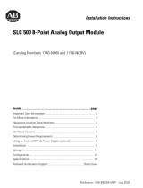
6. Connect the wires to the terminal block and field device as shown in the
following figures and table. The recommended maximum torque is 5 in-
lb. (0.565 Nm) for all terminal screws.
7. To guard against electrostatic damage and improve chassis grounding,
connect one of the shield pins on the terminal block of your module to
the chassis itself.
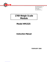
NOTE
Important: For CE compliance, Ferrite EMI Suppressors are needed on
each channel’s terminal block connection. Apply the suppressor close to
the module terminal block, as shown below. A Steward Part 28B2024-0A0
or equivalent is recommended. The Steward 28B2024-0A0 has an
impedance of 157 Ω at 25 MHz, 256 Ω at 100 MHz, and can
accommodate one turn of wire.
Figure 2-1. Ferrite EMI suppressor for CE compliance
8. Repeat steps 1 through 7 for each channel on your module.

2-8 Chapter 2: Installation and Wiring
User’s Manual Pub. 0300128-04 Rev. A
A system may malfunction due to a change in its operating environment.
After installing and wiring your module, check system operation. See the
Allen-Bradley system Installation and Operation Manual for more
information.
Figure 2-2. Wiring diagrams (showing differential outputs)
/