A.O. Smith Burkay HW 300 User manual

Category
Water heaters & boilers
Type
User manual
PLACE THESE INSTRUCTIONS ADJACENT TO BOILER AND
NOTIFY OWNER TO KEEP FOR FUTURE REFERENCE
PRINTED 0210 317693-000
GAS-FIRED COMMERCIAL COPPER BOILERS FOR
HYDRONIC HEATING AND HOT WATER SUPPLY
• INSTALLATION • OPERATION MAINTENANCE • LIMITED WARRANTY
• INDOOR ONLY
MODELS HW 300, 399, 420, 520, 610, 670
UP-FLOW MODELS
WARNING: If the information in this manual
is not followed exactly, a re or explosion
may result causing property damage,
personal injury or death.
Do not store or use gasoline or other
flammable vapors and liquids in the
vicinity of this or any other appliance.
WHAT TO DO IF YOU SMELL GAS
Do not try to light any appliance.
Do not touch any electrical switch; do
not use any phone in your building.
Immediately call your gas supplier
from a neighbor's phone. Follow the
gas supplier's instructions.
If you cannot reach your gas supplier,
call the re department.
Installation and service must be
performed by a qualified installer,
service agency or the gas supplier.
500 Tennessee Waltz Parkway
Ashland City, TN 37015
www.hotwater.com
2
IMPORTANT DEFINITIONS
Qualied Installer: A qualied installer must have ability equivalent to a licensed tradesman in the elds of plumbing,
air supply, venting and gas supply, including a thorough understanding of the requirements of the National Fuel Gas
Code or the Natural Gas and Propane Installation Code as it relates to the installation of gas red boilers. The qualied
installer must have a thorough understanding of this instruction manual.
Service Agency: A service agency also must have ability equivalent to a licensed tradesman in the elds of plumbing,
air supply, venting and gas supply, including a thorough understanding of the requirements of the National Fuel Gas
Code as it relates to the installation of gas red boilers. The service agency must also have a thorough
understanding of this instruction manual, and be able to perform repairs strictly in accordance with the service guidelines
provided by the manufacturer.
Gas Supplier: The Natural Gas or Propane Utility or service who supplies gas for utilization by the gas burning
appliances within this application. The gas supplier typically has responsibility for the inspection and code approval of
gas piping up to and including the Natural Gas meter or Propane storage tank of a building. Many gas suppliers also
offer service and inspection of appliances within the building.
SAFE INSTALLATION, USE AND SERVICE
The proper installation, use and servicing of this water heater is extremely important to your safety and the safety of others.
Many safety-related messages and instructions have been provided in this manual and on your own water heater to warn you and others
of a potential injury hazard. Read and obey all safety messages and instructions throughout this manual. It is very important that the
meaning of each safety message is understood by you and others who install, use, or service this water heater.
DANGER indicates an imminently
hazardous situation which, if not avoided,
will result in injury or death.
This is the safety alert symbol. It is used to alert you to
potential personal injury hazards. Obey all safety
messages that follow this symbol to avoid possible
injury or death.
WARNING indicates a potentially hazardous
situation which, if not avoided, could result
in injury or death.
CAUTION indicates a potentially hazardous
situation which, if not avoided, could result in
minor or moderate injury.
CAUTION used without the safety alert
symbol indicates a potentially hazardous
situation which, if not avoided, could result in
property damage.
WARNING
CAUTION
CAUTION
DANGER
All safety messages will generally tell you about the type of hazard, what can happen if you do not follow the safety message, and how
to avoid the risk of injury.
The California Safe Drinking Water and Toxic Enforcement Act requires the Governor of California to publish a list of substances known to
the State of California to cause cancer, birth defects, or other reproductive harm, and requires businesses to warn of potential exposure
to such substances.
This product contains a chemical known to the State of California to cause cancer, birth defects, or other reproductive harm. This appliance
can cause low level exposure to some of the substances listed in the Act.
3
GENERAL SAFETY
4
SAFE INSTALLATION, USE AND SERVICE.......................................................................................................................................................................... 2
GENERAL SAFETY................................................................................................................................................................................................................ 3
TABLE OF CONTENTS .......................................................................................................................................................................................................... 4
DIMENSIONS AND CAPACITY DATA .................................................................................................................................................................................... 5
INTRODUCTION .................................................................................................................................................................................................................... 7
Grounding Instructions ................................................................................................................................................................................................... 7
Correct Gas .................................................................................................................................................................................................................... 7
Precautions .................................................................................................................................................................................................................... 7
Liquid Petroleum Gas Models ........................................................................................................................................................................................ 7
High Altitude Installations ............................................................................................................................................................................................... 7
CONTROLS AND FUNCTION ................................................................................................................................................................................................ 8
High Limit ....................................................................................................................................................................................................................... 8
Intermittent Ignition Control Module ............................................................................................................................................................................... 8
Thermal Balancer ........................................................................................................................................................................................................... 9
Auto Reset High Limit Control ........................................................................................................................................................................................ 9
Safety Flow Switch ......................................................................................................................................................................................................... 9
Safety Relief Valves...................................................................................................................................................................................................... 10
Tank Temperature Control .............................................................................................................................................................................................11
Thermometers (not installed) ....................................................................................................................................................................................... 12
DRAIN VALVE ...................................................................................................................................................................................................................... 12
GENERAL ............................................................................................................................................................................................................................ 12
Required Ability ............................................................................................................................................................................................................ 12
Location ........................................................................................................................................................................................................................ 12
Air Requirements .......................................................................................................................................................................................................... 13
Chemical Vapor Corrosion............................................................................................................................................................................................ 13
Installation Clearances ................................................................................................................................................................................................. 14
Leveling ........................................................................................................................................................................................................................ 14
System Connections .................................................................................................................................................................................................... 14
VENTING ............................................................................................................................................................................................................................. 14
Venting the Boiler ......................................................................................................................................................................................................... 14
Venting Maintenance .................................................................................................................................................................................................... 16
Venting Sidewall ........................................................................................................................................................................................................... 16
Venting System ............................................................................................................................................................................................................ 16
Venting Tables .............................................................................................................................................................................................................. 17
SYSTEM INSTALLATIONS .................................................................................................................................................................................................. 18
Installations .................................................................................................................................................................................................................. 18
Conventional ........................................................................................................................................................................................................ 18
Linear Temp .......................................................................................................................................................................................................... 18
Water Supply Line ................................................................................................................................................................................................ 19
Expansion Tank .................................................................................................................................................................................................... 19
Vent Valves ........................................................................................................................................................................................................... 20
Manifold Headers ................................................................................................................................................................................................. 20
Cooling Piping ...................................................................................................................................................................................................... 20
Circulating Pump .................................................................................................................................................................................................. 20
Gas Connections .......................................................................................................................................................................................................... 20
Gas Supply Line Purging and Sizing ............................................................................................................................................................................ 21
Gas Pressure Regulators ............................................................................................................................................................................................. 22
WIRING ................................................................................................................................................................................................................................ 23
WIRING DIAGRAMS ....................................................................................................................................................................................................... 24-33
PIPING ............................................................................................................................................................................................................................ 34-39
OPERATION AND START-UP INSTRUCTIONS .................................................................................................................................................................. 39
Important ...................................................................................................................................................................................................................... 39
Filling the System ......................................................................................................................................................................................................... 39
Pilot Alignment and Main Burner .......................................................................................................................................................................................... 39
Lighting Instructions ................................................................................................................................................................................................ 43-44
Checking and Adjusting Input ....................................................................................................................................................................................... 41
Operating Sequence .................................................................................................................................................................................................... 42
REMOVAL OF EXISTING BOILER FROM A COMMON VENTING SYSTEM ..................................................................................................................... 45
GENERAL MAINTENANCE ................................................................................................................................................................................................. 45
Cleaning and Flushing Instructions ...................................................................................................................................................................................... 46
PRE TROUBLESHOOTING ................................................................................................................................................................................................. 46
TROUBLESHOOTING .................................................................................................................................................................................................... 47-54
LIMITED WARRANTY .......................................................................................................................................................................................................... 55
TABLE OF CONTENTS
5
EXTRA OPENING
FOR THERMOMETER
AND RELIEF VALVE
HW-520, 610
AND HW--670
DIMENSIONS AND CAPACITY DATA
TABLE 1
DIMENSIONS IN INCHES
MODELS
HW-300 HW-399 HW-420 HW-520
PROPANE
HW-610/670
NATURAL
HW-610/670
A Overall height 65 (1651) 57-1/8 (1451) 57-1/8 (1451) 68-5/16 (1735) 67 (1702) 64-3/4 (1645)
B Height to Top of Jacket 43-1/4 (1099) 45-1/8 (1146) 45-1/8 (1146) 56-1/4 (1429) 56-1/4 (1429) 56-1/4 (1429)
C Floor to Center Line Water Inlet 36 (914) 38-3/4 (984) 38-3/4 (984) 46 (1168) 46 (1168) 46 (1168)
D Diameter of Jacket 25-1/4 (641) 27 (686) 27 (686) 27 (686) 27 (686) 27 (686)
E Floor to Center Line Water Outlet 12 (305) 12 (305) 12 (305) 12 (305) 12 (305) 12 (305)
F Draft Diverter Outlet Diameter 8 (203) 10 (254) 10 (254) 10 (254) 12 (305) 12 (305)
G Floor to Center Line Gas Inlet 16-1/2 (419) 16-3/4 (425) 16-3/4 (425) 18 (457) 18 (457) 18 (457)
H Overall Depth 29-5/8 (753) 31-1/2 (800) 31-1/2 (800) 36-1/2 (927) 36-1/2 (927) 36-1/2 (927)
J Support Height 9 (229) 9 (229) 9 (229) 9 (229) 9 (229) 9 (229)
K Width of Control String (approx.) 14 (356) 14 (356) 14 (356) 11 (279) 11 (279) 11 (279)
L Pipe Size of Water Inlet (NPT) 1-1/4 1-1/2 1-1/2 2 2 2
M Pipe Size of Water Outlet (NPT) 1-1/4 1-1/2 1-1/2 2 2 2
N Pipe Size of Gas Inlet (NPT) 3/4 1 1 1 1 1
P Control String Plus 1/2 Jacket Diameter (approx.) 26-5/8 (676) 27-1/2 (699) 27-1/2 (699) 24-1/2 (622) 24-1/2 (622) 24-1/2 (622)
S Horizontal Length between Water Inlet and Outlet 5-3/8 (137) 5-1/2 (140) 5-1/2 (140) 5-3/4 (146) 5-3/4 (146) 5-3/4 (146)
T Control String from Jacket 5 (127) 5 (127) 5 (127) 7 (178) 7 (178) 7 (178)
Approximate shipping weight lbs. (Kilograms) 240 (109) 291 (132) 291 (132) 361 (164) 361 (164) 361 (164)
NOTE: All dimensions in inches (millimeters) except pipe size which is NPT
6
TABLE 2, RECOVERY CAPACITIES
Model
Input °F 20 40 50 60 70 80
BTUH (kW) °C 11.1 22.2 27.7 33.3 38.8 44.4
HW 300 300,000 (88)
GPH 1439 719 576 480 411 360
LPH 5448 2724 2179 1816 1556 1362
HW 399 399,000 (117)
GPH 1914 957 765 638 547 478
LPH 7245 3623 2898 2415 2070 1811
HW 420 420,000 (123)
GPH 2014 1007 806 671 576 504
LPH 7627 3813 3051 2542 2179 1907
HW 520 520,000 (152)
GPH 2494 1247 998 831 713 624
LPH 9443 4721 3777 3148 2698 2361
HW 610 610,000 (179)
GPH 2926 1463 1170 975 836 731
LPH 11077 5538 4431 3692 3165 2769
HW 670 660,000 (193)
GPH 3165 1583 1266 1055 904 791
LPH 11985 5992 4794 3995 3424 2996
COMPONENT LOCATION
FIGURE 1.
7
INTRODUCTION
This design complies with the current edition of the ANSI Z21.13
low-pressure boiler standard.
Compliance under this standard implies that when the boiler
underwent test, the gas manifold and control assembly pro vided
on the boiler met safe lighting and other performance criteria.
Detailed installation diagrams are found in this manual. These
diagrams will serve to provide the installer a reference for the
materials and methods of piping necessary. It is essential that
all water, gas piping and wiring be installed as shown on the
diagrams. You should thoroughly read and understand this manual
before installation and/or operation of this boiler.
The factory warranty will be void if the boiler(s) have been
improperly installed or operated.
In addition to these instructions, the boiler(s) shall be installed
in accordance with those installation regulations in force in the
local area where the installation is to be made. These shall be
carefully followed in all cases. Authorities having jurisdiction
should be consulted before installations are made.
In the absence of local codes, the installation must comply with the
current editions, as follows:
In the United States:
The National Fuel Gas Code, ANSI Z223.1/NFPA 54 and the
National Electric Code, NFPA 70.
In Canada:
Installation Code CAN/CSA B149.1 and Canadian Electrical Code,
CSA C22.1.
GROUNDING INSTRUCTIONS
This boiler must be grounded in accordance with the National Electrical
Code, Canadian Electrical Code and/or local codes. Correct wiring is
imperative for proper operation.
This boiler must be connected to a grounded metal, permanent
wiring system, or an equipment grounding conductor must be run
with the circuit conductors and connected to the equipment grounding
terminal or lead on the boiler.
CORRECT GAS
MAKE SURE THE GAS ON WHICH THE BOILER WILL
OPERATE IS THE SAME AS THAT SPECI FIED ON THE
BOILER RATING PLATE. DO NOT INSTALL THE BOILER IF
EQUIPPED FOR A DIFFERENT TYPE OF GAS CONSULT
YOUR SUPPLIER.
PRECAUTIONS
IF THE UNIT IS EXPOSED TO THE FOLLOWING, DO NOT
OPERATE UNTIL ALL CORRECTIVE STEPS HAVE BEEN
MADE BY A QUALIFIED SERVICEMAN:
1. EXPOSURE TO FIRE.
2. IF DAMAGED.
3. FIRING WITHOUT WATER.
4. SOOTING.
IF THE BOILER HAS BEEN EXPOSED TO FLOODING, IT
MUST BE REPLACED.
LIQUEFIED PETROLEUM GAS MODELS
Boilers for propane or liquefied petroleum gas (LPG) are different
from natural gas models. A natural gas boiler will not function
safely on LP gas and no attempt should be made to convert a
boiler from natural gas to LP gas.
LP gas must be used with great caution. It is highly
explosive and heavier than air. It collects first in the low
areas making its odor difficult to detect at nose level.
If LP gas is present or even suspected, do not attempt
to find the cause yourself. Leave the building, leaving
doors open to ventilate, then call your gas supplier or
service agent. Keep area clear until a service call has
been made.
At times you may not be able to smell an LP gas leak.
One cause is odor fade, which is a loss of the chemical
odorant that gives LP gas its distinctive smell. Another
cause can be your physical condition, such as having
a cold or diminishing sense of smell with age. For
these reasons, the use of a propane gas detector is
recommended.
IF YOU EXPERIENCE AN OUT OF GAS SITUATION, DO
NOT TRY TO RELIGHT APPLIANCES YOURSELF. Call
your local service agent. Only trained LP professionals
should conduct the required safety checks in accordance
with industry standards.
HIGH ALTITUDE INSTALLATIONS
Rated inputs are suitable up to 2000 feet (610 m) elevation.
Consult the factory for installation at altitudes over 2000
feet (610 m).
8
HIGH ALTITUDE INSTALLATIONS
IN CANADA
Acceptance of these models for use at altitudes above 2000 feet
(600 m) is based on eld test of the individual installation by the
provincial/state authority having jurisdiction.
IN THE U.S.A.
WARNING
INSTALLATIONS ABOVE 2000 FEET REQUIRE REPLACEMENT
OF THE BURNER ORIFICES IN ACCORDANCE WITH THE
CURRENT EDITION OF THE NATIONAL FUEL GAS CODE
(ANSI Z223.1). FAILURE TO REPLACE THE ORIFICES WILL
RESULT IN IMPROPER AND INEFFICIENT OPERATION OF THE
APPLIANCE RESULTING IN THE PRODUCTION OF INCREASED
LEVELS OF CARBON MONOXIDE GAS IN EXCESS OF SAFE
LIMITS WHICH COULD RESULT IN SERIOUS PERSONAL
INJURY OR DEATH.
For specic orice requirements, please refer to the appropriate
section of the National Fuel Gas Code ANSI Z223.1.
You should contact your gas supplier for any specic changes which
may be required in your area.
Ratings specified by manufacturers for most boilers apply for
elevations up to 2000 feet (600 m). For elevations above 2000 feet
(600 m) ratings must be reduced by a rate of 4% for each 1000 feet
(300 m) above sea level.
Example: If a boiler is rated at 610,000 Btu/hr. at sea level, to operate
the boiler at 5000 feet (1500 m) it must be derated by 20% (4% x 5)
to a new rating of 488,000 Btu/hr.
A. O. Smith does build some models specically for high altitude
service. Please check the rating plate before making changes.
The input reduction is primarily achieved by reducing the size
of the main burner orifices. To do this, the main burner orifices
require replacement with orifices sized for the particular
installation elevation. When ordering, be sure to state the model
number and the altitude of the location where the boiler is being
installed.
Upon field deration of the boiler, adjustment to the gas pressure
regulator is required. See CHECKING AND ADJUSTING
THE INPUT in this manual for inlet and manifold pressure
requirements. Also, due to the input rating reduction required at
high altitudes, the output rating of the appliance is also reduced
and should be compensated for in the sizing of the equipment
for applications.
AUTO RESET HIGH LIMIT
The high limit is a safety device wired in series with the
ignition system. Set the high limit control to approximately 10
0
F
above the maximum designed system temperature. If the
boiler outlet water temperature should exceed the high
limit setting, the main gas valve will close but the circulator
will continue to operate. Maximum adjustable setting is 115
0
C
(239°F) cut-out with a 3
0
C (5
0
F) to 25
0
C (45
0
F) adjustable
differential, see Figure 2.
FIGURE 2.
INTERMITTENT IGNITION CONTROL MODULE
The Honeywell S-8600 control module contains the electronic
components of the system and also serves as a control wiring system
for the controls mounted on the heater. The control module performs
the following functions:
1. Checks for safe-start by sensing for a false ame condition on
start-up.
2. Generates a potential of 15,000 volts for spark ignition of the
pilot burner.
3. Opens the pilot valve.
4. Discontinues ignition spark when the pilot flame is established.
The S-8600 control used on propane gas models provides
safety lockout if the pilot fails to ignite within the pilot flame
establishing period. The S-8600 control used on natural
gas models continues trial for ignition until pilot flame
is established.
5. After proof of pilot ame, opens then main valve.
6. On a power loss, shuts the heater down. When power is restored
it will begin a new ignition cycle.
7. On a loss of ame, shuts off main gas and starts trial for pilot ignition.
PLEASE SEE TROUBLESHOOTING SECTION FOR MORE
INFORMATION.
S-8600 INTERMITTENT IGNITION
CONTROL MODULE (IID)
FIGURE 3.
CONTROLS AND FUNCTION
9
THERMAL BALANCER
Figure 4 shows the internal wiring of the thermal balancer. The
device may be tested after disconnecting the four leads from their
respective terminals on the unit.
1. Apply a test light to the yellow and red leads.
The lamp should light as the contact in this circuit is normally
closed when the resistor is cool.
2. Apply a light to the black and yellow leads.
The lamp should not light as the contact in this circuit is normally
open when the resistor is cool.
3. Remove the test light.
4. Apply 120 volts to the white and red leads which power the 1900
ohm resistor. After a warming period the contacts of the thermal
balancer should operate.
5. Remove the test light.
6. Apply the test light as described in steps 1 and 2.
While the resistor is still warm the lamp indications should be the
opposite as described previously.
FIGURE 4.
MANUAL RESET HIGH LIMIT
This boiler is equipped with a manual reset high limit switch,
located under the small cover on the side of the jacket, see
Figure 5. This device provides positive shutdown of the
boiler in the event of boiler or system malfunction. Should the
surface temperature of the copper tubing heat exchanger
reach 250°F (120°C), the high limit switch will activate,
the gas valve will close, the pilot and main burners will be
extinguished. If the high limit switch should shut off unit, check
the following conditions:
No water in boiler.
Restricted water flow through the boiler.
Improper wiring (boiler firing without circulator
operating).
Pump failure.
After correcting failure condition remove the protector switch cover
and push the reset button. The high limit switch may be reset after
the coil surface cools to 6°F (3.3°C) below the trip setting.
HIGH LIMIT SWITCH
FIGURE 5.
SAFETY FLOW SWITCH
The safety ow switch is a safety device which must be installed at
the water outlet of the unit to prevent main burner operation in the
event of inadequate water ow through the unit.
An accessory package containing a safety ow switch is available
for this application.
This switch may be mounted in a horizontal pipe line or a vertical
pipe line with upward water ow. Do not install the switch where the
water ow is downward.
For proper performance mount the switch in a section of pipe where
there is a straight run of at least 5 pipe diameters on each side of the ow
switch (i.e. do not locate adjacent to valves, elbows, orices, etc.).
The ow switch shall be mounted in a standard 1-1/2" x 1-1/2" x 1"
tee for a 1-1/2" pipe application. For larger pipe sizes use a reducing
tee in order to keep the switch as close to the pipe as possible. Install
the ow switch in the branch (top) opening of the reducing tee and
provide adequate paddle length in the ow stream. For example in
a 2" pipe installation use a 2" x 2" x 1" reducing tee. For 2", or 3"
pipe use paddle segments as supplied. For other pipe sizes (i.e.
1-1/4", 1-1/2" and 2-1/2") trim the paddle to the proper pipe size, see
Figure 6 on page 10. If a standard tee is used, install a face or hex
bushing in the top opening. The paddle must be adjusted or trimmed
to the size of the pipe in which it will be installed.
CAUTION
Any part of the paddle must not touch the pipe or any restrictions in
the pipe. Screw the ow switch in position so the at of the paddle
is at right angles to the ow. The arrow on the side case must point
in the direction of the ow.
TABLE 3 - SAFETY FLOW SWITCH
Minimum Pipe Rate
Model Number
Contacts Closed
(Flow)
Contacts Open
(No Flow)
GPM LPM GPM LPM
HW-300 5.8 22.0 3.7 14.0
HW-399 7.5 28.4 5.0 18.9
HW-420 7.5 28.4 5.0 18.9
HW-520 13.7 51.9 9.5 36.0
HW-610/670 13.7 51.9 9.5 36.0
The safety ow switch may be eld adjusted to obtain higher
minimum ow rates than those shown in table 3.
10
CAUTION
Paddle must be trimmed at the dotted arc. It must not touch the pipe or have any restriction when installed.
FIGURE 6.
To adjust the ow rate setting:
1. Remove the ow switch cover.
2. For higher ow rate - turn the range adjusting screw clockwise.
3. For lower flow rate - turn the range adjusting screw
counterclockwise.
CAUTION
The switch is factory set at approximately the minimum ow rate, see
Table 3 on page 9. It must not be set lower than the factory setting as
this may result in the switch failing to return at 'no ow' condition.
4. Replace ow switch cover. Where units are installed in multiples,
each boiler must be individually protected by a safety ow switch.
SAFETY RELIEF VALVES
Your local code authority may have other specic relief valve
requirements not covered below.
WARNING
THE PURPOSE OF A SAFETY RELIEF VALVE IS TO AVOID
EXCESSIVE PRESSURE OR TEMPERATURE INTO THE STEAM
RANGE WHICH MAY CAUSE SCALDING AT FIXTURES, TANK
EXPLOSION, SYSTEM OR BOILER DAMAGE.
TO AVOID SCALDING OR WATER DAMAGE A DRAIN LINE MUST
BE CONNECTED TO A RELIEF VALVE TO DIRECT DISCHARGE
TO A SAFE LOCATION. A DRAIN LINE MUST NOT BE REDUCED
FROM THE SIZE OF THE VALVE OUTLET AND IT MUST NOT
CONTAIN ANY VALVES BETWEEN THE BOILER AND THE
RELIEF VALVE OR THE RELIEF VALVE AND THE DRAIN EXIT.
IN ADDITION, THERE SHOULD NOT BE ANY RESTRICTIONS
IN A DRAIN LINE NOR SHOULD IT BE ROUTED THROUGH
AREAS WHERE FREEZING CONDITIONS MIGHT OCCUR. DO
NOT THREAD OR CAP THE DRAIN LINE EXIT. RESTRICTING
OR BLOCKING A DRAIN LINE WILL DEFEAT THE PURPOSE OF
THE RELIEF VALVE AND MAY CREATE AN UNSAFE CONDITION.
INSTALL A DRAIN LINE WITH A DOWNWARD SLOPE SUCH THAT
IT NATURALLY DRAINS ITSELF.
If any safety relief valve is replaced, the replacement valve must comply
with the current editions of the ASME Boiler and Pressure Vessel
11
Code, Section IV or CSA B51, as applicable. Select a relief valve with
a discharge NOT less than the boiler input, and a pressure rating NOT
exceeding the working pressure of any component in the system.
A. O. Smith supplies a 125 psi relief valve for hot water supply systems
and 50 psi relief valve for space heating application.
An ASME rated temperature and pressure relief valve must be installed
on each and every water storage tank in a hot water supply system.
The storage tank temperature and pressure (T & P) relief valve must
comply with the applicable contruction provisions of the Standard
for Relief valves and Automatic Gas Shutoff Devices for Hot Water
Supply Systems, Z21.22 - CSA 4.4. The T & P valve must be of the
automatic reset type and not embody a single-use type of fusible
plug, cartridge or linkage.
The T & P relief valve should have a maximum temperature rating
of 100°C (210°F), a pressure rating NOT exceeding the lowest
rated working pressure of any system component, and a discharge
capacity exceeding the total input of the water boilers supplying
water to the storage tank.
Locate the T & P relief valve (a) in the top of the storage tank or (b)
in the side of the tank on centerline within upper 6 inches from the
top of the tank. See Figures 28 to 33, Pages 34 to 38. Tapping shall
be threaded in accordance with the latest version of the Standard for
Pipe Threads, General Purpose (inch), ANSI/ASME B.120.1.
Mark location with a class III Label. See ANSI Z21.10.1, Part 1,
Marking, See CAN/CSA B149.
TANK TEMPERATURE CONTROL
The water temperature in the storage tank is controlled by the Tank
Temperature Control. The sensing element is mounted inside the
hot water storage tank.
DANGER
HOT WATER TEMPERATURES REQUIRED FOR AUTOMATIC
DISHWASHER AND LAUNDRY USE CAN CAUSE SCALD BURNS
RESULTING IN SERIOUS PERSONAL INJURY AND/OR DEATH.
THE TEMPERATURE AT WHICH INJURY OCCURS VARIES
WITH THE PERSON’S AGE AND TIME OF EXPOSURE. THE
SLOWER RESPONSE TIME OF CHILDREN, AGED OR DISABLED
PERSONS INCREASES THE HAZARDS TO THEM. NEVER ALLOW
SMALL CHILDREN TO USE A HOT WATER TAP, OR TO DRAW
THEIR OWN BATH WATER. NEVER LEAVE A CHILD OR DISABLED
PERSON UNATTENDED IN A BATHTUB OR SHOWER.
The tank temperature control is adjustable from 100°F (37.7°C) to
220°F (104.4°C). It is recommended that lower water temperatures
be used to avoid the risk of scalding. It is further recommended, in all
cases, that the water temperature be set for the lowest temperature
which satises the user’s hot water needs. This will also provide the
most energy efcient operation of the water heater and minimize
scale formation.
THE WATER HEATER SHOULD BE LOCATED IN AN AREA WHERE
THE GENERAL PUBLIC DOES NOT HAVE ACCESS TO SET
TEMPERATURES. SETTING THE WATER TEMPERATURE AT
120°F (49°C) WILL REDUCE THE RISK OF SCALDS. Some states or
provinces require settings at specic lower temperatures. Below you
will nd listed the approximate time-to-burn relationship for normal
adult skin. Valves for reducing point-of-use temperature by mixing
cold and hot water are available. Also available are inexpensive
devices that attach to faucets to limit hot water temperatures. Contact
a licensed plumber or the local plumbing authority.
12
Water Temperature
Time to Produce 2nd & 3rd
Degree Burns on Adult Skin
OVER: 170°F (77°C)
160°F (71°C)
150°F (65°C)
140°F (60°C)
130°F (54°C)
120°F (49°C)
Nearly Instantaneous
About 1/2 second
About 1-1/2 seconds
Less than 5 seconds
About 30 seconds
More than 5 minutes
USE ANTI-SCALD VALVE(S) in the hot water system to reduce
the risks of scalds at points of use such as lavatories, sinks
and bathing facilities.
A change in water temperature in the storage tank lower than
the Tank Temperature Control setting will cause the sensor to
close its contacts and consequently energize the boiler.
If the Tank Temperature Control is out of calibration, replace it
with a new one; do not attempt to fix this control.
WARNING
SHOULD OVERHEATING OCCUR OR THE GAS SUPPLY FAIL
TO SHUT OFF, TURN OFF THE MANUAL GAS CONTROL
VALVE TO THE APPLIANCE.
GENERAL
THERMOMETERS
Thermometers should be obtained and field installed as shown
in the installation diagrams.
Thermometers are installed in the system as a means
of detecting a possible liming con di ti on in the bo il er.
An increase of 5°F (3°C) over the normal temperature
rise t h r o u g h the b o i l e r i s a n i n d i c a t i o n that l i m e is
p r e s e n t . T h e t e r m " t e m p e r a t u r e r i s e " d e s i g n a t e s
the difference between the boiler inlet and outlet water
temperature.
An increase of 5°F (3°C) above the recorded temperature
rise may signif y a liming condition in the c oils or heat
e x c h a n g e r . R e f e r t o C L E A N I N G A N D F L U S H I N G
section of this manual for deliming instructions.
Re c o r d tempe r a t u r e rise at initia l st a r t- u p fo r f ut u r e
reference.
DRAIN VALVE (Not Supplied)
A drain valve must be obtained and installed on each boiler
and tank for draining purposes, see installation diagrams in
this manual.
REQUIRED ABILITY
Installation or service of this boiler requires ability equivalent to that
of a licensed tradesman in the eld involved. Plumbing, air supply,
venting, gas supply and electrical work are required.
LOCATION
When installing the boiler, consideration must be given to proper
location. Location selected should be as close to the stack or chimney
as practicable with adequate air supply and as centralized with the
piping system as possible. This location should also be such that the
gas ignition system components are protected from water (dripping,
spraying, etc.) during appliance operation and service (circulator
replacement, control replacement, etc.).
THE BOILER MUST NOT BE INSTALLED ON CARPETING.
THE BOILER SHOULD NOT BE LOCATED IN AN AREA WHERE
IT WILL BE SUBJECT TO FREEZING.
LOCATE IT NEAR A FLOOR DRAIN. THE BOILER SHOULD BE
LOCATED IN AN AREA WHERE LEAKAGE FROM THE BOILER OR
CONNECTIONS WILL NOT RESULT IN DAMAGE TO THE ADJACENT
AREA OR TO LOWER FLOORS OF THE STRUCTURE.
WHEN SUCH LOCATIONS CANNOT BE AVOIDED, A METAL
DRAIN PAN SHOULD BE INSTALLED UNDER THE BOILER. Such
pans should be fabricated with sides at least 60mm (2-1/2") deep,
with length and width at least 50mm (2") greater than the diameter
of the boiler and must be piped to an adequate drain. The pan must
not restrict combustion air ow.
WARNING
KEEPING BOILER AREA CLEAR AND FREE FROM COMBUSTIBLE
MATERIALS, GASOLINE AND OTHER FLAMMABLE VAPORS AND
LIQUIDS.
WARNING
THERE IS A RISK IN USING FUEL BURNING APPLIANCES
SUCH AS BOILERS IN ROOMS OR AREAS WHERE GASOLINE,
OTHER FLAMMABLE LIQUIDS OR ENGINE DRIVEN EQUIPMENT
OR VEHICLES ARE STORED, OPERATED OR REPAIRED.
FLAMMABLE VAPORS ARE HEAVY AND TRAVEL ALONG THE
FLOOR AND MAY BE IGNITED BY THE IGNITER OR MAIN BURNER
FLAMES CAUSING FIRE OR EXPLOSION. SOME LOCAL CODES
13
PERMIT OPERATION OF GAS APPLIANCES IF INSTALLED
18 INCHES OR MORE ABOVE THE FLOOR. THIS MAY
REDUCE THE RISK IF LOCATION IN SUCH AN AREA CANNOT
BE AVOIDED.
WARNING
FLAMMABLE ITEMS, PRESSURIZED CONTAINERS OR ANY
OTHER POTENTIAL FIRE HAZARDOUS ARTICLES MUST
NEVER BE PLACED ON OR ADJACENT TO THE BOILER.
OPEN CONTAINERS OF FLAMMABLE MATERIAL MUST
NOT BE STORED OR USED IN THE SAME ROOM WITH
THE BOILER.
A hot water boiler installed above radiation level or as required
by the authority having jurisdiction, must be provided with a low
water cutoff device at the time of boiler installation.
AIR REQUIREMENTS
Provisions for combustion and ventilation air in accordance
w i t h t h e c u r r e n t e d i t i o n o f t h e N a t i o n a l F u e l G a s
C o d e , A N S I Z 2 2 3 . 1 , C A N / C S A B 1 4 9 . 1 , I n s t a l l a t i o n
C o d e s , o r a p p l i c a b l e p r o v i s i o n s o f t h e l o c a l
building codes.
Provisions for vent, bleed and gas relief lines (when applicable).
Keep appliance area free of combustible or ammable liquids.
Do not obstruct the ow of combustion or ventilating air.
WARNING
FOR SAFE OPERATION PROVIDE ADEQUATE AIR FOR
COMBUSTION AND VENTILATION. AN INSUFFICIENT SUPPLY
OF AIR WILL CAUSE RECIRCULATION OF COMBUSTION
PRODUCTS RESULTING IN AIR CONTAMINATION THAT
MAY BE HAZARDOUS TO LIFE. SUCH A CONDITION OFTEN
WILL RESULT IN A YELLOW, LUMINOUS BURNER FLAME,
CAUSING CARBONING OR SOOTING OF THE COMBUSTION
CHAMBER, BURNERS AND FLUE TUBES AND CREATES A
RISK OF ASPHYXIATION.
Unconned Space
In buildings of conventional frame, brick or stone construction,
unconned spaces may provide adequate air for combustion, and
draft hood dilution.
If the unconfined space is within a building of tight construction
(buildings using the following construction: weather stripping,
heavy insulation, caulking, vapor barrier, etc.) air for combustion,
ventilation, and draft hood dilution must be obtained from
outdoors or spaces freely communicating with the outdoors. The
installation instructions for confined spaces in tightly constructed
buildings must be followed to ensure adequate air supply.
Conned Space
(a) U. S. Installations
When drawing combustion and dilution air from inside a conventionally
constructed building to a conned space, such a space shall be
provided with two permanent openings, ONE WITHIN 12 INCHES
OF THE ENCLOSURE TOP AND ONE WITHIN 12 INCHES OF THE
ENCLOSURE BOTTOM. Each opening shall have a free area of at
least one square inch per 1000 Btuh of the total input of all appliances
in the enclosure, but not less than 100 square inches.
If the confined space is within a building of tight construction,
air for combustion, ventilation, and draft hood dilution must be
obtained from outdoors. When directly communicating with the
outdoors or communicating with the outdoors through vertical
ducts, two permanent openings, located in the above manner,
shall be provided. Each opening shall have a free area of not
less than one square inch per 4000 Btuh of the total input of
all appliances in the enclosure. If horizontal ducts are used,
each opening shall have a free area of not less than one
square inch per 2000 Btuh of the total input of all appliances
in the enclosure.
(b) Canadian Installations
Ventilation of the space occupied by the boiler(s) shall be
provided by an opening for ventilation air at the highest practical
point communicating with outdoors. The total cross-sectional
area shall be at least 10% of the area of the combustion air
opening but in no case shall the cross-sectional area be less
than 10 square inches (6500 mm
2
).
In additional to the above, there shall be permanent air supply
opening(s) having a cross-sectional area of not less than 1
square inch per 7,000 BTUH (310 mm
2
/KW) up to and including
1,000,000 BTUH plus 1 square inch per 14,000 BTU in excess
of 1,000,000 BTUH. This opening(s) shall be located at, or
ducted to, a point neither more than 18" (450 mm) nor less
than 6 inches (150 mm) above the floor level.
Where power vented equipment is used in the same room as the
boiler, sufcient air openings must be supplied.
UNDERSIZED OPENINGS MAY RESULT IN INSUFFICIENT AIR
FOR COMBUSTION.
WHERE AN EXHAUST FAN IS INSTALLED IN THE SAME ROOM
WITH A BOILER, SUFFICIENT OPENINGS FOR AIR MUST BE
PROVIDED IN THE WALLS.
UNDERSIZED OPENINGS WILL CAUSE AIR TO BE DRAWN
INTO THE ROOM THROUGH THE CHIMNEY, CAUSING POOR
COMBUSTION. SOOTING MAY RESULT WITH AN INCREASED
RISK O F ASPHYXIATION.
CHEMICAL VAPOR CORROSION
WARNING
COR R O SION OF THE FLUE WAY S AND VENT SY STEM
MAY OCCUR IF AIR FOR COMBUSTION CONTAINS
C E R T A I N C H E M I C A L V A P O R S W H I C H B R E A K
DOW N IN TO A C I DS AT HI GH TEMP E R ATURE. SU C H
COR R O SION MAY RES U LT I N FAI L U RE AND R ISK O F
ASPHYXIATION.
Water boiler corrosion and component failure can be caused
by the heating and breakdown of airborne chemical vapors.
Spray can propellants, cleaning solvents, refrigerator and air
conditioning refrigerants, swimming pool chemicals, calcium
and sodium chloride, waxes, and process chemicals are typical
compounds which are corrosive. These materials are corrosive
at very low concentration levels with little or no odor to reveal
their presence. Products of this sort must not be stored near
the boiler. Also, air which is brought in contact with the water
boiler should not contain any of these chemicals. If necessary,
uncontaminated air should be obtained from remote or outside
sources.
14
INSTALLATION CLEARANCES
These boilers are approved for installation on combustible ooring
in an alcove with minimum clearance to combustibles of:
TABLE 4
HW
300
HW
399
HW
420
HW
520
HW
610 & 670
TOP 28" (711.2) 32" (812.8) 24" (609.6) 24" (609.6) 24" (609.6)
SIDES 6" (152.4) 6" (152.4) 24" (609.6) 24" (609.6) 24" (609.6)
REAR 6" (152.4) 6" (152.4) 24" (609.6) 24" (609.6) 24" (609.6)
VENT 6" (152.4) 6" (152.4) 6" (152.4) 6" (152.4) 6" (152.4)
Two inch (50.8mm) clearance is allowable from combustible
construction for hot water pipes.
Sufcient area should be provided at the front and rear of the unit
for proper servicing. Clearances of 24 inches (609.4mm) in the
rear and 48 inches (1,219mm) in the front are required by code.
In a utility room installation, the door shall be wide enough to allow
the boiler to enter or to permit the replacement of another appliance
such as a water heater.
LEVELING
Each unit should be checked after installation to be certain that it is level.
If the unit is not level, insert metal shims under the legs of the unit
to correct this condition.
SYSTEM CONNECTIONS
The system installation must conform to these instructions
and to the requirements of the local code authority having
jurisdiction. Good practice requires that all heavy piping be
supported.
VENTING
A TYPICAL BOILER INSTALLATION
FIGURE 7.
VENTING THE BOILER - STANDARD VENTING
WARNING
THE INSTRUCTIONS IN THIS S ECTION ON VENTING
THE BOILER MUST BE FOLLOWED TO AVOID CHOKED
COMBUSTION OR RECIRCUL ATION OF FLUE GASES.
SUCH CONDITIONS CAUSE SOOTING OR RISKS OF FIRE
AND ASPHYXIATION.
TYPE B VENTING MAY BE USED WITH THESE BOILERS. ALL
LOCAL UTILITY REGULATIONS ON VENTING SHOULD BE
FOLLOWED.
For boilers for connection to gas vents or chimneys, vent sizing,
installation and termination shall be in accordance with the
current edition of the National Fuel Gas Code, ANSI Z223.1, or
CAN/CSA B149.1, Installation Codes, or applicable provisions
of the local building codes.
Vent connectors serving appliances vented by natural draft shall
not be connected into any portion of mechanical draft systems
operating under positive pressure.
The minimum distance from adjacent public walkways, adjacent
buildings, openable windows and building openings shall not be
less than those values specified in the National Fuel Gas Code,
ANSI Z223.1 and/or CAN/CSA B149.1, Installation Codes;
Stack or chimney must be a minimum height of 12" (305mm)
above the annual snow fall to prevent blockage.
15
Building materials must not come in contact with combustion
products from stack or chimney, due to the degradating properties
of ue products.
Flue products must have a minimum clearance of 4 feet (1.22m)
horizontally from, and in no case above or below, unless a 4-foot
(1.22m) horizontal distance is maintained, from electric meters, gas
meters, regulators and relief equipment.
CAN/CSA B149.1, Installation Code species a 6 foot horizontal
vent terminal clearance to gas and electric meters and relief devices
(this clearance is specied as 4 feet in the U.S. under the National
Fuel Gas Code, ANSI/Z223.1). Therefore instruction, which species
compliance with the 4 foot clearance, as applies in the U.S. only, and the
CAN/CSA B149.1 Installation Code applies in Canada.
1. DRAFT HOOD
The draft hood furnished with this boiler must be installed without
alteration. Provision must be made if the boiler is installed in conned
space or a small boiler room to accommodate draft hood spillage and
avoid risks described above. The upper air opening called for in the
AIR REQUIREMENTS section of this manual is for this purpose.
2. VENT CONNECTION
Size and install proper size vent pipe. Do not reduce pipe size to
less than that of the draft hood outlet.
Horizontal runs of vent pipe shall be securely supported by
adequately placed (approximately every 4 feet or 1 meter), non-
combustible hangers and/or slip joints suitable for the weight
and design of the materials employed to prevent sagging and
to maintain a minimum upward slope of 1/4" (21mm/m) per foot
from the boiler to the vent terminals, see Figure 8. Dampers or
other obstructions must not be installed in the vent. Be sure
that the vent pipe does not extend beyond the inside wall of
the chimney.
VENT PIPE INSTALLATION
FIGURE 8.
Where a continuous or intermittent back draft is found to exist the
cause must be determined and corrected. A special vent cap may
be required. If the back draft cannot be corrected by the normal
methods or if a suitable draft cannot be obtained, a blower type
ue gas exhauster may be employed to ensure proper venting and
correct combustion if permitted by local codes.
WARNING
FAILURE TO CORRECT BACK DRAFTS WILL CAUSE AIR
CONTAMINATION AND UNSAFE CONDITIONS.
Vent connectors serving appliances vented by natural draft shall not
be connected into any portion of mechanical draft systems operating
under positive pressure.
3. CONNECTING BOILER TO A COMMON VENT
Do not connect the boiler to a common vent or chimney with solid
fuel burning equipment. This practice is prohibited by many local
building codes as is the practice of venting gas red equipment to
the duct work of ventilation systems.
Where a separate vent connection is not available and the vent pipe
from the boiler must be connected to a common vent with oil burning
equipment, the vent pipe should enter the common vent or chimney
at a point ABOVE the ue pipe from the oil red unit.
Where two or more appliances vent into a common vent connector
or manifold, the area of the common vent or vent connector should
at least equal the area of the largest vent connector plus 50% of the
areas of the additional draft hood outlets.
When removing a boiler from a system with a common vent, use
the following steps:
Be sure the other appliances connected to the common vent are
not in operation.
Seal any unused openings in the common venting system.
Visually inspect the venting system for proper size and horizontal pitch
and determine there is no blockage or restriction, leakage, corrosion
and other deciencies which could cause an unsafe condition.
WARNING
Ensure sufcient supply and ventilation air. Under no circumstances
should the equipment room where the boiler is installed ever be under
negative pressure. Insufcient air supply can interfere with combustion
and ventilation of this boiler resulting in unsafe conditions.
Insofar as is practical, close all building doors and windows and
all doors between the space in which the appliances remaining
connected to the common venting system are located and other
spaces of the building. Turn on clothes dryers and any appliance not
connected to the common venting system. Turn on any exhaust fans,
such as range hoods and bathroom exhausts, so they will operate
at maximum speed. Close replace dampers.
Place in operation the appliance being inspected. Follow the
lighting instructions. Adjust thermostat so appliance will operate
continuously.
Test for spillage at the draft hood relief opening after ve minutes of
main burner operation. Use the ame of a match or candle.
After it has been determined that each appliance remaining connected
to the common venting system properly vents when tested as outlined
above, return doors, windows, exhaust fans, replace dampers and
any other gas burning appliance to their previous conditions of use.
Any improper operation of the common venting system should be
corrected so the installation conforms with the current edition of
CAN/CSA B149.1 (current edition). When resizing any portion of
the common venting system, the common venting system should
be resized to approach the minimum size as determined using the
appropriate tables in CAN/CSA B149.1.
16
4. MULTIPLE VENT TABLE
Table 5 on page 17 has been compiled to show the material
sizes in a Type B doublewall combined vent system. Refer to
CAN/CSA B149 .1 (current edition), or the ASHRAE 1983 Equipment
Volume for further information.
A combined vent system is one in which two or more boilers at one
level are attached to a common vent.
In order to use table 5, the connector rise and total vent height must
be known. Connector rise is vertical distance from the draft hood outlet
to the point where the manifold connection is made. Total vent height
is the least vertical distance from a draft hood outlet to the top of the
vent. Local codes or utility requirements often govern termination
height. ULC listed doublewall gas vents, up through 24" (610mm)
diameter, can be installed in heated and unheated areas and can
pass through oors, ceilings, partitions, walls and roofs, provided
the required one inch clearance is observed. These vents should be
installed in accordance with CAN/CSA B149.1 (current edition).
EXAMPLE SHOWING USE OF THE HW-610 COMBINED VENT
SIZING TABLE
FIGURE 9.
VENTING MAINTENANCE - STANDARD VENTING
It is recommended that the heating surfaces and vent piping of
the appliance be checked every six months for dust, deterioration
and carbon deposits. Remove all soot or other obstructions from
chimney and ue which will retard free draft. Replace any damaged
or deteriorated parts of the venting system.
Qualied servicers should follow this procedure when the boilers
external heating surfaces and vent pipe need cleaning.
CAUTION
DO NOT USE A NYLON BRUSH OR OTHER STATIC CREATING
MATERIAL TO CLEAN DUST AND CARBON DEPOSITS FROM
HEATING SURFACES AND VENT.
SUCH DEPOSITS ARE FLAMMABLE AND MAY BE IGNITED BY
STATIC ELECTRICITY. USE A METAL BRUSH TO MINIMIZE THE
DANGER OF EXPLOSION.
1. Turn off the electrical power (main manual gas shutoff and pilot
valves, if applicable).
Allow boiler parts and vent to cool before disassembly.
2. Remove the boiler draft diverter and vent pipe running to the chimney.
Check parts and chimney for obstructions and clean as necessary.
3. Remove burner from boiler and other metal parts as required to
clean and vacuum the heat exchanger and combustion coils.
Refer to parts list supplied with this manual for disassembly aid.
4. Reinstall the parts removed in steps 2 and 3.
Be sure the vent pipe has a minimum upward pitch of one quarter
inch per foot of length (21mm/m) and is sealed as necessary.
5. Restore electrical power and gas supply to boiler.
Place boiler in operation by following the lighting instructions
in this manual.
Check for gas leaks and proper boiler and vent operation.
VENTING - SIDEWALL (OPTIONAL) POWER VENT SYSTEM
If you are installing the optional Power Vent Kit, refer to your
HW Power Vent Kit Installation Instructions for proper wiring
and installation procedures. Contact your local A. O. Smith
representative for details.
VENTING SYSTEM
HAVE VENTING SYSTEM CHECKED EVERY SIX MONTHS FOR
OBSTRUCTIONS AND/OR DETERIORATION IN VENT PIPING.
A. Insofar as is practical, close all doors, windows and air inlets to
the building. Turn on all exhaust fans (range hood, bathroom
exhaust, etc.) so they will operate at their maximum speed.
Close replace dampers.
B. After allowing appliance to operate for ve minutes, test for
spillage at the draft hood relief opening.
C. “CHECKING THE DRAFT. Operate vent connected gas utilization
equipment for several minutes and check to see that the combustion
products are going up the chimney or gas vent properly by passing
a lighted match or taper around the edge of the relief opening of
the draft hood. If the chimney or gas vent is drawing properly, the
match ame will be drawn into the draft hood. If not, the combustion
products will tend to extinguish this ame. IF THE COMBUSTION
PRODUCTS ARE ESCAPING FROM THE RELIEF OPENING OF
THE DRAFT HOOD, DO NOT OPERATE THE EQUIPMENT UNTIL
PROPER ADJUSTMENT OR REPAIRS ARE MADE TO PROVIDE
ADEQUATE DRAFT THROUGH THE CHIMNEY OR GAS VENT.”
D. Next, turn on all other fuel burning appliances within the same
room so they will operate at their full input.
Repeat step C above, checking the draft on each appliance.
FIGURE 10.
17
TABLE 5, COMBINED VENT SIZING TABLES
MODEL HW-300 BOILER
Input: 300,000 Btuh Draft Hood Outlet 8"
Required Connector or Smoke Pipe Diameter
Connector
Rise in Feet
Total Vent Height (Measured in Feet Above Draft Hood)
10 15 20 30 40 50 60 80 100
Connector Diameter (in Inches)
1 10 10 10 10 10 10 10 10 10
2 10 10 10 10 10 10 10 10 10
3 10 10 10 10 10 10 10 10 10
4 or more
Number
if Units
Combined
Total Input
Btuh x 1000
Total Vent Height (Measured in Feet Above Draft Hood)
10 15 20 30 40 50 60 80 100
Manifold and Common Vent Diameter (in Inches)
2 600 14 12 12 12 10 10 10 10 10
3 900 16 14 14 14 12 12 12 12 12
4 1200 18 16 16 14 14 14 14 12 12
MODEL HW-399 BOILER
Input: 399,000 Btuh Draft Hood Outlet 10"
Required Connector or Smoke Pipe Diameter
Connector
Rise in Feet
Total Vent Height (Measured in Feet Above Draft Hood)
10 15 20 30 40 50 60 80 100
Connector Diameter (in Inches)
1 12 12 12 12 12 12 12 12 12
2 12 12 12 10 10 10 10 10 10
3 12 10 10 10 10 10 10 10 10
4 or more 10 10 10 10 10 10 10 10 10
Number
if Units
Combined
Total Input
Btuh x 1000
Total Vent Height (Measured in Feet Above Draft Hood)
10 15 20 30 40 50 60 80 100
Manifold and Common Vent Diameter (in Inches)
2 798 14 14 14 12 12 12 12 12 12
3 1197 18 16 16 14 14 14 14 14 12
4 1596 20 20 18 16 16 16 14 14 14
MODEL HW-420 BOILER
Input: 420,000 Btuh Draft Hood Outlet 10"
Required Connector or Smoke Pipe Diameter
Connector
Rise in Feet
Total Vent Height (Measured in Feet Above Draft Hood)
10 15 20 30 40 50 60 80 100
Connector Diameter (in Inches)
1 12 12 12 12 12 12 12 12 12
2 12 12 12 10 10 10 10 10 10
3 12 10 10 10 10 10 10 10 10
4 or more 10 10 10 10 10 10 10 10 10
Number
if Units
Combined
Total Input
Btuh x 1000
Total Vent Height (Measured in Feet Above Draft Hood)
10 15 20 30 40 50 60 80 100
Manifold and Common Vent Diameter (in Inches)
2 840 14 14 14 12 12 12 12 12 12
3 1260 18 16 16 14 14 14 14 14 12
4 1680 20 20 18 16 16 16 14 14 14
MODEL HW-520 BOILER
Input: 520,000 Btuh Draft Hood Outlet 10"
Required Connector or Smoke Pipe Diameter
Connector
Rise in Feet
Total Vent Height (Measured in Feet Above Draft Hood)
10 15 20 30 40 50 60 80 100
Connector Diameter (in Inches)
1 14 14 14 12 12 12 12 12 12
2 12 12 12 12 12 12 12 12 12
3 12 12 12 12 10 10 10 10 10
4 or more 12 12 12 12 10 10 10 10 10
Number
if Units
Combined
Total Input
Btuh x 1000
Total Vent Height (Measured in Feet Above Draft Hood)
10 15 20 30 40 50 60 80 100
Manifold and Common Vent Diameter (in Inches)
2 1040 16 16 14 14 14 14 12 12 12
3 1560 20 18 18 16 16 14 14 14 14
4 2080 22 22 20 18 18 18 16 16 14
5 2600 26 24 22 20 20 18 18 18 18
6 3120 28 26 24 22 22 20 20 18 18
7 3640 30 28 26 24 24 22 22 20 20
8 4160 32 30 28 26 24 24 22 22 20
MODEL HW-610 BOILER
Input: 610,000 Btuh Draft Hood Outlet 12"
Required Connector or Smoke Pipe Diameter
Connector
Rise in Feet
Total Vent Height (Measured in Feet Above Draft Hood)
10 15 20 30 40 50 60 80 100
Connector Diameter (in Inches)
1 16 14 14 14 14 14 14 14 14
2 14 14 14 14 14 12 12 12 12
3 14 14 12 12 12 12 12 12 12
4 or more 12 12 12 12 12 12 12 12 12
Number
if Units
Combined
Total Input
Btuh x 1000
Total Vent Height (Measured in Feet Above Draft Hood)
10 15 20 30 40 50 60 80 100
Manifold and Common Vent Diameter (in Inches)
2 1220 18 18 16 16 14 14 14 14 14
3 1830 22 20 20 18 18 16 16 16 14
4 2440 26 24 22 20 20 18 18 18 16
5 3050 28 26 26 24 22 22 20 20 18
6 3660 32 28 28 26 24 24 22 22 20
7 4270 34 32 30 28 26 24 24 22 22
8 4880 36 34 32 30 28 26 26 24 24
9 5490 38 36 34 30 30 28 28 26 24
10 6100 40 38 36 32 30 30 28 26 26
11 6710 42 38 38 34 32 30 28 28 26
12 7320 44 42 38 36 34 32 32 30 28
MODEL HW-670 BOILER
Input: 660,000 or 670,000 Btuh Draft Hood Outlet 12"
Required Connector or Smoke Pipe Diameter
Connector
Rise in Feet
Total Vent Height (Measured in Feet Above Draft Hood)
10 15 20 30 40 50 60 80 100
Connector Diameter (in Inches)
1 16 14 14 14 14 14 14 14 14
2 14 14 14 14 14 12 12 12 12
3 14 14 12 12 12 12 12 12 12
4 or more 12 12 12 12 12 12 12 12 12
Number
if Units
Combined
Total Input
Btuh x 1000
Total Vent Height (Measured in Feet Above Draft Hood)
10 15 20 30 40 50 60 80 100
Manifold and Common Vent Diameter (in Inches)
2 1220 18 18 16 16 14 14 14 14 14
3 1830 22 20 20 18 18 16 16 16 14
4 2440 26 24 22 20 20 18 18 18 16
5 3050 28 26 26 24 22 22 20 20 18
6 3660 32 28 28 26 24 24 22 22 20
7 4270 34 32 30 28 26 24 24 22 22
8 4880 36 34 32 30 28 26 26 24 24
9 5490 38 36 34 30 30 28 28 26 24
10 6100 40 38 36 32 30 30 28 26 26
11 6710 42 38 38 34 32 30 28 28 26
12 7320 46 44 40 38 36 34 34 32 30
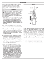
Known: (5) model HW-610 boilers. (See illustration).
Connector rise - 2' (Note 1' is minimum). Total vent
height 30'.
Problem: Determine diameter of connector, manifold and
common vent.
Procedure: Enter the top of the HW-610 table (total vent height)
at 30' and the side at 2' (connector rise). A 14"
connector diameter is indicated for each connector
rise.
To determine the manifold and common vent size, enter table on this
page (total vent height) at 30 and the side at 5 boilers. A manifold
diameter of 24" (610 mm) is indicated.
18
1. CONVENTIONAL INSTALLATIONS
All modern hydronic type boilers are exceptionally fast heating units.
The low water volumes in relation to ring rates require special
attention to water ow rates for smooth, efcient operation. These
considerations for the A. O. Smith copper heat exchanger boilers
are covered below.
Conventional 20
0
F (10
0
C) drop in systems for a fully loaded boiler
will maintain the following approximate ow rates:
MODELS GPM (LPM)
HW-300 23 (87)
HW-399 30 (114)
HW-420 35 (132)
HW-520 39 (148)
HW-610/670 46 (175)
Figure 7 on page 14 shows a typical installation of the boiler with pipe
sizing and circulator selected by the installer to provide adequate
water ow whenever the boiler is ring.
In a system with several large zones of which any might be smaller
than approximately 1/3 of the system should include a hydronic
balancer as shown in Figure 7. The balancer connects between
the system supply and the return line before the circulator inlet.
Adjustment of the balancing cock should permit adequate boiler ow
rate when only the smallest zone is in operation.
Attention should be given to balancing inputs and water ow rates
where wide variations of system ow rates can occur.
The recommended minimum ow rates that will result in approximately
50
0
F (30
0
C) temperature rise across the boiler are as follows:
MODELS GPM (LPM)
HW-300 9 (34)
HW-399 12 (45)
HW-420 14 (53)
HW-520 16 (61)
HW-610 18 (69)
HW-670 20 (76)
If system ow rate is unknown, or if zoning creates extreme variations
in ow rates, the boiler should be installed as shown in Figure 11 on
this page for A. O. Smith LINEAR-TEMP installations.
2. LINEAR-TEMP INSTALLATIONS
A. New Installations
A. O. Smith LINEAR-TEMP systems have been designed to provide
efcient, trouble-free operation of the boiler sizes covered in this
manual with any of the following conditions:
a. Unknown system ow rate
b. Varying ow rate as with zoned systems
c. Multiple boiler installations
Figure 11 on this page shows piping and accessory arrangement
for a boiler pumped independent of the primary system mains. Pipe
sizing and boiler loop pump selection data are shown in Table 6 for
several different temperature rises across the boilers.
ONE BOILER INSTALLED
INDEPENDENT OF THE PRIMARY SYSTEM
FIGURE 11.
Total heating requirements for the building can be supplied by a
series of boiler loops all connecting to a common pipe joining the
system supply and return mains. The supply and return branches of
each boiler loop must join the common pipe only a short nipple length
apart. The different sets of branches should be installed reasonably
close together, but not necessarily to the short nipple length as
required for the supply and return of each set. These branches may
be made with tees or with welded connections.
The installer is reminded that the total boiler ow rates need not
match the system ow rate.
TABLE 6.
PUMP AND PIPE SIZING DATA
(PIPING FROM TEES IN MAIN TO BOILER BRANCHES)
Model Temp. Rise °F (°C) G.P.M. *Pump Size Pipe Size
HW-300
20 (10)
30 (15)
30 (15)
40 (20)
23
15
15
11
1-1/2" PR
150
125
100
2"
1-1/2"
1-1/4"
1"
HW-399
20 (10)
35 (15)
40 (20)
40 (20)
30
20
15
15
60-13
1-1/2" HV
150
125
2"
1-1/2"
1-1/2"
1-1/4"
HW-420
20 (10)
35 (15)
40 (20)
40 (20)
32
21
16
16
60-13
1-1/2" HV
150
125
2"
1-1/2"
1-1/2"
1-1/4"
HW-520
20 (10)
20 (10)
35 (17)
40 (20)
39
26
23
20
2-1/2"
1-1/2" HV
1-1/2" HV
150
2-1/2"
2"
1-1/2"
1-1/2"
HW-610/670
20 (10)
30 (15)
35 (17)
40 (20)
51
34
29
25
60-13
2-1/2"
2"
1-1/2" HV
3"
2-1/2"
2"
1-1/2"
NOTE: Pipe loop sizes and pump selections based on
50 equivalent feet of pipe and ttings.
*All pump sizes listed are B & G model numbers.
SYSTEM INSTALLATIONS
19
NO. SUGGESTED ITEMS FOR INSTALLATION
1
Short pipe nipple and pair of boiler loop tees in piping
between system supply and return. One set per each group
of boilers.
2 Boiler pipe loop. See piping sizing data.
3 Boiler circulator. See pump sizing data.
4 Thermometer.
5 Theraltimeter.
6 Plug cock to control ow rate.
7
Safety ow switches. For interlock with other systems or
instead of low water cutoff.
8 Relief valve.
9
With one -300, -399 or -420 item 9 is - sensing element of
remote control.
With a group of -300's, -399's or -420's, item 9 is - for 1st
boiler, the sensing element as above. For additional boilers,
install a 2nd limit control if required by local codes. With
any -520, -610 or 670 boilers, install 2nd limit control here if
required by local code.
BOILER INLET - OUTLET SIZES
10
HW-300 - 1-1/4", HW-399 - 1-1/2", HW-420 - 1-1/2",
HW-520 & HW-610 - 2".
10
HW-300 - 1-1/4", HW-399 - 1-1/2", HW-420 - 1-1/2", HW-520
& HW-670 - 2".
MINIMUM BRANCH SIZES TO BOILERS
11
HW-300 - 1-1/4" HW-520, 610 (Single boiler
HW-399 - 1-1/2" per pump) 2"
HW-420 - 1-1/2"
11
HW-300 - 1-1/4" HW-520, 670 (Single boiler
HW-399 - 1-1/2" per pump) 2"
HW-420 - 1-1/2"
12
Flow control valve. Required only if ow rate of system
primary is excessive for size of boiler branch tees or if chilled
water main is above boilers.
13 System supply temperature thermometer.
14
Boiler headers for three (3) boilers can be larger than pipe
loop, if desired, to aid in balancing.
The system flow rate is selected to give the desired system
temperature drop - depending on the design criteria.
The boiler generator ow rates, on the other hand, should be
selected to give the temperature rise through the generator that is
both economical and offers the best generator efciency.
The boiler temperature rise is normally between 10
0
C and 20
0
C (20
0
F
and 40
0
F). The system temperature that will be introduced to the
boiler (inlet temperature) plus the selected boiler temperature rise
selected from PUMP AND PIPE SIZING DATA should not exceed
the high limit control setting of 115
0
C (240
0
F).
There should be a relation of the minimum system load to the size
boiler selected as the rst ring or base boiler. This will stabilize
operation during minimum load periods.
B. Commercial Boiler Replacements
Application of LINEAR-TEMP
®
to a commercial boiler replacement
with an old multiple pump installation is an excellent way to modernize
the system. The A. O. Smith boiler(s) should be installed on a pipe
loop with a separate circulating pump selected from PUMP AND
PIPE SIZING DATA TABLE.
Figure 12 shows a line drawing of how the system headers should be
connected to the pipe loop installed with the replacement boiler(s).
Make-up water connections and accessories are not shown.
SCHEMATIC OF THE LINEAR-TEMP
®
SYSTEM
FIGURE 12.
Supply and return headers of the old system should be connected
to the boiler loop with a pair of tees set close together. The boiler
loop pump and the boiler(s) should be wired to operate only when
any of the system pumps are in operation. The number of zone
pumps that may be in operation at any particular time will take
their required ow rate out from the rst tee in the boiler piping.
This water will be circulated through the proper branches from
the supply header to the zones calling for heat. The water will be
brought back to the return header and then into the second tee in
the boiler pipe loop. There will be no conict between the boiler
pump and the zone pumps when the two tees in the boiler loop
are placed close together.
Normal use of ow control valves is required to prevent cross
circulation of zones as with any multiple pump system. Flow control
is not required on boiler circuit.
Attention should be given to balancing gas inputs and water ow
rates. Large systems with multiple boilers should include main water
temperature control (with or without outdoor reset) to stage the boilers
on and off in relation to the load on the system.
3. WATER SUPPLY LINE
These boilers can be used ONLY in a forced circulation hot water
heating system. Since most forced circulation systems will be of
the closed type, install the water supply line as shown on piping
diagrams, Figure 7 to 11 on pages 14 and 18.
Fast lling of large pipe, old radiator installations and pressure
purging of series loop systems (where high pressures are not
available) requires bypassing of the pressure reducing valve.
Generally, pressure purging is not possible with a well pump system.
High point air venting is essential.
If the system is of the open type, a pressure reducing valve
will not be required as the water supply to the system will be
controlled by a manually operated valve. An overhead surge
tank is required.
4. EXPANSION TANK
CAUTION
A closed system will exist if a check valve (without bypass), pressure
reducing valve (without bypass), or a water meter (without bypass) is
installed in the cold water line between the water heater and street
main (or well).
Excessive pressure may develop causing premature tank failure or
intermittent relief valve operation. This is not a warranty failure. An
expansion tank or a similar device may be required in the inlet supply
line between the appliance and the meter or valve to compensate for
the thermal expansion of water under supply pressure, see Figure 7
on page 14.
An air separator as shown in the piping diagrams is recommended
especially for modern commercial hydronic systems.
20
5. VENT VALVES
It is recommended that automatic, loose key or screwdriver type
vent valves be installed at each convector or radiator.
6. MANIFOLD HEADERS
Split systems with individual supply and return lines from the boiler
room should normally have this piping connected to supply and
return manifold headers near the boiler. To achieve good water
distribution with maximum pressure drop for several circuits,
manifolds of at least 2-1/2" (64mm) diameter are suggested on
HW-399, HW-420, HW-520, HW-610 and HW-670 units. HW-300
units should have 1-1/2" (38mm) diameter manifolds.
The circuits should be spaced on the header at a minimum of
3" (76mm) center to center. Install a balancing cock in each return line.
Manifold headers are recommended for split systems with or without
zone valves and also those installations with zone circulators. If the
system is to be split at remote points, good practice requires special
attention be given to main pipe sizing to allow balancing of water ow.
The boiler piping system of a hot water boiler connected to heating
coils located in air handling units where they may be exposed to
refrigerated air circulation must be equipped with ow control valves or
other automatic means to prevent gravity circulation of the boiler water
during the cooling cycle.
7. COOLING PIPING
When the boiler is used in conjunction with a refrigeration system it
must be installed so that the chilled medium is piped in parallel with
the boiler with appropriate valves to prevent the chilled medium from
entering the boiler, see Figure 13.
Water temperature in the heating system must be reduced to less
than 100
0
F (38°C) before cooling system is started, or damage to
the chiller unit may occur.
SCHEMATIC SHOWING PROPER PIPING ISOLATION
OF THE BOILER FROM THE CHILLER
FIGURE 13.
If the boiler is connected to chilled water piping or its heating coils
are exposed to refrigerated air, the boiler piping system must be
equipped with ow valves or other automatic means to prevent gravity
circulation through the boiler during the cooling cycle.
8. CIRCULATING PUMP
CONSTANT CIRCULATING PUMP OPERATION OF THE BOILER
VOIDS THE WARRANTY. Constant water ow through the unit
will “wash away the copper’s natural protective coating. This is
called velocity erosion. This erosion is not as great a problem when
intermittent circulating operation is used per the recommended
installation procedure. Constant circulation of water through the
building’s system main is permissible as long as the water does not
constantly ow through the boiler. Only all bronze or stainless steel
circulators are to be used with the unit when it is installed in HOT
WATER SUPPLY SYSTEMS.
A TYPICAL CIRCULATING PUMP
FIGURE 14.
Although each circulator that requires oiling is oiled and operated by
the manufacturer, IT MUST BE OILED AGAIN BEFORE OPERATED.
Oil the three oil cups (2 on the motor, 1 on the pump) as instructed
on the oil tube supplied with the unit, see Figure 14 on this page.
Thereafter, during the heating season, lubricate the three oil cups at
least once every four months. Combination heating-cooling systems
should be lubricated every four months year ‘round.
Use 2 or 3 teaspoonsful in bearing oil cups or 12 drops in the motor
oil cups, see Figure 14 on this page. Use No. 20 non-detergent
motor oil.
Follow the same oiling procedure if a replacement circulator is
installed into the system.
GAS CONNECTIONS
WARNING
THIS BOILER IS NOT INTENDED TO OPERATE AT GAS SUPPLY
PRESSURE OTHER THAN SHOWN ON THE RATING PLATE.
EXPOSURE TO HIGHER GAS SUPPLY PRESSURE MAY CAUSE
DAMAGE TO GAS VALVES WHICH CAN RESULT IN FIRE OR
EXPLOSION. IF OVERPRESSURE HAS OCCURRED SUCH AS
THROUGH IMPROPER TESTING OF GAS LINES OR EMERGENCY
MALFUNCTION OF THE SUPPLY SYSTEM, THE GAS VALVES MUST BE
CHECKED FOR SAFE OPERATION. MAKE SURE THAT THE OUTSIDE
VENTS ON THE SUPPLY REGULATORS AND THE SAFETY VENT
VALVES ARE PROTECTED AGAINST BLOCKAGE. THESE ARE PARTS
OF THE GAS SUPPLY SYSTEM, NOT THE BOILER. VENT BLOCKAGE
MAY OCCUR DURING ICE BUILD-UP OR SNOW STORMS.
WHEN LOCAL CODES REQUIRE A MAIN MANUAL SHUTOFF
VALVE OUTSIDE THE BOILER JACKET, A SUITABLE MAIN
MANUAL SHUTOFF VALVE MUST BE INSTALLED IN A LOCATION
COMPLYING WITH THOSE CODES.
IT IS IMPORTANT TO GUARD AGAINST GAS VALVE FOULING
FROM CONTAMINANTS IN THE GAS WAYS. SUCH FOULING
MAY CAUSE IMPROPER OPERATION, FIRE OR EXPLOSION.
IF COPPER SUPPLY LINES ARE USED THEY MUST BE
CERTIFIED FOR GAS SERVICE.
BEFORE ATTACHING THE GAS LINE BE SURE THAT ALL GAS
PIPE IS CLEAN ON THE INSIDE.
  • Page 1 1
  • Page 2 2
  • Page 3 3
  • Page 4 4
  • Page 5 5
  • Page 6 6
  • Page 7 7
  • Page 8 8
  • Page 9 9
  • Page 10 10
  • Page 11 11
  • Page 12 12
  • Page 13 13
  • Page 14 14
  • Page 15 15
  • Page 16 16
  • Page 17 17
  • Page 18 18
  • Page 19 19
  • Page 20 20
  • Page 21 21
  • Page 22 22
  • Page 23 23
  • Page 24 24
  • Page 25 25
  • Page 26 26
  • Page 27 27
  • Page 28 28
  • Page 29 29
  • Page 30 30
  • Page 31 31
  • Page 32 32
  • Page 33 33
  • Page 34 34
  • Page 35 35
  • Page 36 36
  • Page 37 37
  • Page 38 38
  • Page 39 39
  • Page 40 40
  • Page 41 41
  • Page 42 42
  • Page 43 43
  • Page 44 44
  • Page 45 45
  • Page 46 46
  • Page 47 47
  • Page 48 48
  • Page 49 49
  • Page 50 50
  • Page 51 51
  • Page 52 52
  • Page 53 53
  • Page 54 54
  • Page 55 55
  • Page 56 56

A.O. Smith Burkay HW 300 User manual

Category
Water heaters & boilers
Type
User manual

Ask a question and I''ll find the answer in the document

Finding information in a document is now easier with AI